한국추진공학회 2009년도 추계학술대회 논문집 pp.433~438 2009 KSPE Fall Conference
* Agency for Defense Development 1-6 E-mail: [email protected]
추진기관용 C/SiC 복합재료의 특성 평가
김연철*
The Performance Evaluation of C/SiC Composite for Rocket Propulsion Systems
Yun Chul Kim
ABSTRACT
The main objective of this research effort is to develop the performance of C/SiC composites manufactured by LSI (Liquid Silicon Infiltration) method for solid and liquid rocket propulsion system and ensure the performance analysis technique. The high performance and reliability of C/SiC composite are proved for solid and liquid rocket propulsion system. And the performance analysis technique related to mathematical ablation model is originated.
초 록
고체 및 액체 추진기괸에 적용하기 위하여 액체 실리콘 함침법(LSI)을 이용한 C/SiC 복합재료를 개발하였다. 연소시험을 통하여 C/SiC 복합재료의 우수한 성능을 확인하였으며 산화에 의한 삭마 모 델을 제시 하였다.
Key Words: C/SiC(탄소/실리콘카바이드), Composite(복합재료), Ablation(삭마), Solid Rocket(고체로 켓), Liquid Engine(액체엔진), LSI(액체 실리콘 함침법)
1. Introduction
Composites have been used throughout history, i.e., straw in bricks, metal rod-reinforced concrete and lightweight aerospace structures. Fiber reinforced polymer matrix composite materials are being introduced in ever-increasing quantities in military systems and have become a key element in the Department of Defense's effort to lighten the force. However, polymer matrix
composites have an inherent temperature limitation based on their hydrocarbon structure. The high temperature alternative to high density metals is ceramics, offering weight savings as well high temperature capability and oxidation resistance.
In recent years, there has been a surge of interest in the design, manufacturing and testing of ceramic matrix composite (CMC) components for a number of aerospace and ground based applications. The potential applications of CMC in the aerospace industry include combustor liners, exhaust nozzles, a number of other aircraft gas turbine and space
propulsion components [1-2]. The ground-based applications of these materials include hot gas filters, high-pressure heat exchanger tubes and combustor liners in industrial gas turbine engines. In addition, there are a number of potential uses of CMC for the first wall and blanket components of nuclear reactors.
At present, the majority of the approaches for the manufacturing of continuous fiber-reinforced ceramic matrix composites are based on fabricating single or multiple pieces [1-3].
The main features of thermo-structural composites (TSCs) are their highly specific mechanical properties, high thermal conductivity, excellent behavior to thermal shocks; endurance to very high temperature, and easy fabrication. TSCs provide a much lighter-weight solution than refractory metals.
With systematic use of high performance composite materials, many countries have significantly decreased the inert mass of its space propulsion systems. TSCs are made of carbon or silicon carbide(SiC) fibres (labeled
“texture” or “perform”), linked together by the parameters can be tuned up in order to meet the mission/design requirements (fibers selections, type and compositions, deformation, laying-up, etc.).
2. Experiments
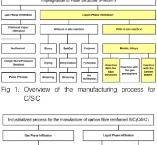
In principal, there exist numerous processing routes to infiltrate the matrix system into the fiber perform. Conventional powder processing techniques used for making monolithic ceramics are mostly not suitable and rather unconventional techniques to avoid damage of the fiber preforms are applied. They can be distinguished between the impregnation either by gas phase or by liquid phase infiltration (Figure 1). Three different techniques are currently used in an industrial scale for the production of C/SiC composites (Figure 2).
Fig 1. Overview of the manufacturing process for C/SiC
Fig. 2. Processes for the industrial manufacture of C/SiC
The best method for manufacturing carbon fiber reinforced silicon carbide composites (C/SiC) is impregnation of the starting fibrous carbon base, having certain porosity, with a carbide-forming metal melt.
The greatest impact on the impregnation process is exerted by temperature. At high temperatures, the melt spreads rapidly. The limiting stage of impregnation is the movement of liquid in pores of the body being impregnated under the action of the capillary pressure.
The kinetics of impregnation is determined primarily by the porous structure of the base (effective radius of pores, their shape and amount) and the melt viscosity.
Figure 3 gives an overview of the LSI-process which can be split into three major steps. The fiber preform fabrication starts with the manufacture of carbon fiber reinforced plastic composites with polymeric matrices of high carbon yield.
Fig. 3. The technological manufacturing process of C/SiC
2.1 Preform design
The conversion of continuous carbon fibers and fabric into a useful structure entails the fabrication of a textile perform at some point in the process. The tape lay-up scheme is the most straight forward approach and the only approach in the case of large diameter non-weaving fibers.
Fig. 4. Various methods for tape wrap and layup of fabric.
2.2 model for LSI process
The carbon fiber reinforced plastic (CFRP) green compact is produced. This CFRP is then pyrolysed at temperatures ranging from normally 1100–2000 K, converting the thermosetting resin matrix into a glassy carbon one. In this step excessive cracking is observed, driven by the heavy shrinkage of the matrix, which is macroscopically prevented by the carbon fibers. The first contact of molten silicon leads to the immediate formation of silicon carbide layers at the capillary walls.
Due to this fact, the chemical reaction of silicon carbide formation is mainly controlled by diffusion of silicon atoms through the SiC layer into the reaction zone (Figure 5).
Fig. 5. Formation of SiC at the capillary wall.
2.3 Design model for thermal performance test The void spaces and matrix cracks are illustrated in Figure 6 where the microstructure of a 2-D C/SiC composite is shown. The oxidation of carbon in the interior of C/SiC composites is strictly tied to the transport of oxygen into and the transport of oxides out of the material. Any viable oxidation model for C/SiC composites must include the solution of species transport equations as the transport has a direct impact on the rate of carbon oxidation. Oxidation models have been developed in the past in order to study the physics of the oxidation process in carbon fiber-reinforced composites.
Fig. 6. Morphology of 2D C/SiC composite.
In order to determine effective characteristics of C/SiC composite materials, in accordance
Carbon fiber
SiC Si
Pore
with the concept of the asymptotic averaging method it is necessary to solve preliminarily special local problems over a periodicity cell.
Isotropic materials under high temperature consists of three phase: initial carbon fiber phase(a), SiC matrix phase (b), new solid SiO2phase(p)andgasphase(g)insidepores.
We can derive the equation for the change in density ρc/sic of ablative C/SiC under heating
⎥⎦
⎢ ⎤
⎣
⎡ ⋅ −
⋅
− ⋅
⋅ +
−
=1 Γ Γexp ρJ Γβ
∫
exp( RTE )dTρ (T)
ρ a
c/sic 0
0 c/sic
0 c/sic
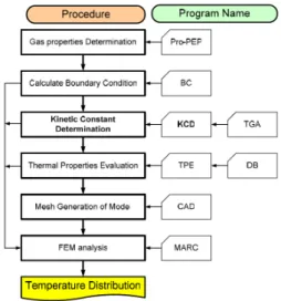
2.4 Finite Element Model for thermal analysis For the design and sizing of ablating propulsion heat shields, it is imperative to have a reliable numerical procedure which can compute surface recession rate, in-depth pyrolysis and internal temperature histories under general heating conditions. The two dimensional program was developed and integrated with the commercial finite element code, MARC. The goal of the present work is to develop a simulation system that can predict surface recession, shape change, in-depth pyrolysis and internal thermal response for a two dimensional TPS/structure system under general high temperature and pressure conditions. MARC code is well-suited to simulate the heat transfer in a complex interior structure. The in-depth thermal reaction solver codes are integrated through the use of MARC’s user-supplied boundary subroutines (Figure 7).
This system should significantly reduce the computational and human effort required to design and analyze a propulsion heat shield and attached structure.
The governing equations and numerical procedures of the two dimensional model are presented in the first. Computation results obtained by applying this procedure for analysis of the heat shield for a liquid and solid rocket system
Fig. 7. Flow chart for FEM analysis
3. Results and discussion
Proof or overstress testing a component has been obtained by multiple tests of C/SiC materials in TGA, arc plasma test facilities, Liquid Rocket Engine, Solid Rocket Motor. The table. 1 summarizes the perform materials, design, analysis and the types of test facilities which might be used to evaluate these issues.
Table 1. Test matrix of C/SiC composites
Ar c plasma
C/P1→HT1000→IPi2→HT2200→LSI(30/10/55/5) C/P1→HT1000→IPi2→HT2200→LSI(65/5/20/10)
3 point bending
C/P1→HT1000→IPi1→HT1000→LSI(20/10/65/5) C/P1→HT1000→IPi1→HT1000/2200→LSI(30/10/55/5) C/P1→HT1000→IPi1→HT2200→LSI ( 30/10/55/15)
Liquid Rocket Engine
C/P1 ,3 , 4, 5→HT1000→IPi1, 2→HT2200→ LSI(30/10/55/5)
C/P1 ,3 , 4, 5→HT1000→IPi1, 2→HT2200→ LSI(65/5/20/10)
Solid Rocket Engine
C/P1 ,2 , 3→HT1000→IPi1, 2→HT2200→LSI( 30/10/55/5)
C/P1 ,2 , 3→HT1000→IPi1, 2→HT2200→LSI( 65/5/20/10)
Thermo-gravimetric analysis (TGA) has been carried out to investigate the kinetics of the oxidation reaction. There are several factors which introduce uncertainty into the results of TGA investigations such as specimen particle size and surface area. Figure 8 shows TGA curves recorded under air atmospheres. The
reaction is initiated at a temperature of between 400℃ and is substantially complete when the temperature has risen above < 1200℃
200 400 600 800 1000 1200 1400
0.0 0.1 0.2 0.3 0.4 0.5 0.6 0.7 0.8 0.9 1.0
experiment calculated experiment calculated
C:Si:SiC:pore = 65:5:20:10 %
C:Si :SiC:pore = 30:10:55:5 %
TGA
Residual weight(%)
Temperature(℃)
Fig. 8. Mass loss of C/SiC in air
The plasma arc is on-line and generates a very high heat flux (up to 3000 W/cm2).Theablationtestwasperformedusinganarc plasma torch and the characteristic values were calculated based on ablation performance. The results of ablation test show that ablation mechanism is almost melting process of pure Si, SiC and the oxidation process of carbon fiber and carbon matrix (Figure 9). In principal, chemical reactions of SiC with oxygen lead to the formation of SiO, SiO2, CO and CO2, the latter of which is of negligible importance at the expected temperatures.
Fig. 9. Scheme of ablative surface
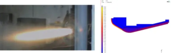
The analyses covered the temperature distributions at various positions along the combustion chamber axis and at the combustor exit. Figure 10 give the thermal fields during the firing. The temperatures of combustion liner slightly increase during the burning. But the temperature of the steel case did not increase. At the end of the firing (10 sec), temperatures of combustion liner and steel case are respectively equal to 670°K and 300°K. As shown in the figure 10, the temperature distribution show that the temperature of steel case approach to 900K at the end of the firing time (200 sec) from simulation. In the future we will be able to test the C/SiC combustion tube at firing time 300 sec after the elimination of flame instability of combustion.
Fig. 10. Firing Liquid Engine and temperature distribution
The solid rocket test bed is a key part of the product evaluation and verification. The objective of this test bed system definition subtask is the establishment of requirements for a valid and economical approach to nozzle design verification that incorporates both subscale and full-scale test environments.
Figure 11 describes the rocket components and the result of thermal analysis.
Fig. 11. Firing Solid Rocket Propulsion and temperature distribution
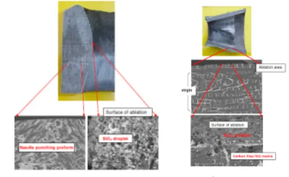
We did not find any other crack in nozzle component. The white solid films, which are the result of melting of SiO2 ,and Al2O3, were founded in the surface of exit cone (Figure 12).
Fig. 12. Ablation surface of the C/SiC throat and exit cone
This work is for the development of high performance Carbon/Silicon carbide (C/SiC) composites using Liquid Silicon Infiltration (LSI) technology. C/SiC composites are interesting materials for an increasing number of applications in the aerospace industry as well as many others.
From the design, manufacturing and firing test, finally we can conclude that
▸ The LSI process leads to a damage tolerant ceramic material, which has a significantly lower component fabrication time and therefore reduced component costs compared with other CMC manufacturing processes
▸ The steady state mass loss correlation of the form
RT) exp( E ) ρ (ρ ρ Γ
J
ρ A
c/sic c/sic b a,
0
c/sic ⋅ − −
−β
∂ =
∂ 1 ∞
T
were obtained from reduction of the TGA test data.
▸ The diffusion process play a great role in the regulation of mass loss rate in active oxidation, that high local heat and mass transfer coefficients correspond to high local mass loss rates in the regime of active oxidation.
▸ Solid Rocket Motor test was performed. At the end of the firing, temperatures of nozzle throat and steel case are respectively equal to 560°K and 300°K. We did not find any other crack in nozzle component.
References
1. Y.C.Kim, et al., Method for manufacturing carbon/silicon carbide composite, US Patent,US6838120(2005).
2. Y.C.Kim, et al., Method for manufacturing carbon/silicon carbide composite, FR Patent, FR 2820737 (2005).
3. V. I. Trefilov, Ceramic- and Carbon-Matrix Composites, Chapman & Hall (1995).