Worn Wheel/Rail Contact Simulation and Cultivated Shear Stresses
Z. Noori*·M. Shahravi·M.A. Rezvani
1. Introduction
By developing the science and with the advent of new tech- nologies, time and money become the same things. Therefore, having a fast and reliable transportation system is a constant concern. Railway transportation system, nowadays, is the first choice in urban transportation which can satisfy both pas- sengers and investors. Moreover, the fuel consumption and air pollution of the new railway systems are in a more efficient standard than other transportation systems, and such charac- teristics is very interesting for the governments [1]. Although it should not be dismissed controlling the maintenance costs in every railway system is of the primary priorities after founding the system, since that can participate retrieving the invest- ments, etc. consequently, every strategy which can decrease the costs is precious.
Nowadays, we can be agreed that subway system is one of the dominant choices for the urban transportation system which needs the special control for an efficient utilization.
Among a variety of subjects which compel high costs in such a system, the wear phenomenon is doubtless one of the most important defects [2]. Indeed, a hard contact between wheel and rail causes the major maintenance costs, albeit being useful and also being the main factor for fuel (energy) efficiency in the railway system. Crack, fatigue, fracture, and derailment are other examples following the wear phenomenon. Profile evo- lution, too, definitely occurs during the utilization which makes the dynamic condition of the train worse as well [3].
There are different ways to manage these defects namely profile optimization [4] applying drive assistance systems [5], prediction of profile evolution [6,7] and many other expensive ways for instance designing the light bogies by applying the composites, producing more wear resistant alloys for the wheel and rail, etc. The first logical action can be getting information about the contact phenomenon as the subway works. Indeed, discovering the profile evolution and followed stresses during the utilization of the system can carry out the major behavior of defects resulted by the wear phenomenon. Based on the- oretical and experimental studies, the max shear stresses cre- ated in the contact patch are the principal reasons for fracture and fatigue defects; therefore, an investigation of the behavior of the shear stresses by logged distance is approached in the present paper [8].
The studies, particularly, focus on track 2 of the Tehran metro system in order to determine the behavior of shear stresses in the worn wheels and rails measured by field scru- tinizes. To approach this aim, field measurement procedure took place for more than three years in order to obtain the pro- file evolutions of wheels/rails; this precious measurement is accomplished by implementing the Miniprof equipment which can scan the geometrical dimensions of profiles. After a long field measurement, the outcomes are classified by max amounts of erosion and deformation. Subsequently, the worst eroded model is considered for analyses. All elected profiles are modeled and meshed in the form of surfaces and then the final 3D meshed elements are generated.
Analyzing the rolling stock shear stresses of the worst defor- mation behaviors, LSDYNA EXPLICITE software is imple- mented; after applying the exact mechanical properties of the real wheel/rail and also geometric states of the contact. Before Abstract
Railway system is today the most efficient way for transportation in many cases in several forms of application.Yet, wear phenomenon, profile evolution, fatigue, fracture, derailment are the major worries (financial and safety) in this system which force significant direct and indirect maintenance costs. To improve the cyclic maintenance procedures and the safety issues, it can be very satisfactory to be informed of the state of wheel/rail interaction with mileage. In present paper, an investigation of the behavior of the shear stresses by logged distance is approached, by implementing the field measure- ment procedure, in order to determine the real conduct of the most important cause of defects in wheel/rail contact, shear stress. The results coming from a simulation procedure indicate that the amounts of shear stresses are still in high-magni- tudes when the wheel and rail are completely worn; even though in simulation based on the laboratory measurements of profile evolutions, the stresses become significantly reduced by logged distance.
Keywords
: Contact Simulation, Profile Deformation, Field Measurement, Finite Element, Shear Stress*Corresponding author.
Tel.: +98-4-417-1907, E-mail : [email protected]
©
The Korean Society for Railway 2013
http://dx.doi.org/10.7782/JKSR.2013.16.2.093
starting the running process, the other critical conditions affect- ing the wheel/rail interactions based on the track 2 of the Tehran metro system are taken into account. Such factors are obtained from the worst utilization condition, for instance, the sharpest curve, the highest speed on the curve, the max axle load possible, the max amounts of angle of attack and Cant angle, and the other considerations. Consequently, all shear stresses obtained by logged distance regarding the worn wheel/
rail interactions, indicate the worst comportment of shear stress's alterations in the normal utilization of the system.
2. Profile Evolution Measurements
2.1 Investigation of Worn Profiles
The field measurement is the main advantage of this paper by which the real behavior of the profile evolution in track 2 of the Tehran subway system is discovered by logged distance.
Since, every railway system on account of its specific uti- lization has its own model for profile evolution, using the other outcomes coming from the other subway systems, or applying the laboratory measurements will not be satisfying. Therefore, the group applied the field measurement by sponsoring and supporting the Tehran Urban & Suburban Co., albeit field stud- ies are more expensive and much more time consumer than laboratory measurements.
To approach the precision results, two tips should be con- sidered before begging the measurement process: First, choos- ing several wheels and rails implemented in diverse positions along the track and within the fleet, and second, continuing the procedure for a long enough time. The aim of first point is to take every behavior into account for various wheels and rails, since the contact interaction will not be the same for every ele- ment. The second tip, additionally, brings out the importance of time in the project, indeed in this arrangement the results will not be affected by specific usage condition of the system in a particular era of utilization. By taking these prerequisites, the wheels and rails are marked by some IDs, and then we sched- ule measurement times during a long investigation in rea- sonable frequency for particular groups of wheels/rails. During the measuring process, the system works as usual and there is no implemented hardware or something on the track or train just a device applied for a short time and then will be removed.
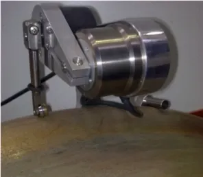
The device used for scanning the profile evolutions is elec- tromechanical equipment by which the coordinates on the con- tact surface are gathered. This equipment entitled Miniprof is applied in two models, wheel or rail profile scanning. Fig. 1 shows a Miniprof implemented on a wheel. The device pos- sesses a magnetic wheel cab move in touch with the profiles let to a precious measurement. Indeed, Miniprof senses the coor- dinates on the wheel’s/rail’s profile and sends them to the com-
puter in a categorizing software [9].
In more than three years, the process is done for various ele- ments periodically. The core regions of wheel and rail mea- sured are wheel’s flange height/width and rail’s vertical, horizontal, and 45 degree profile evolutions. By these factors, the complete deformation of both wheel and rail can be dis- covered with Miniprof device. During the worn profile scan- ning for each ID, the coaxial cable of the device should be under a great attention in order to be free of any disturbing causes such as electric and magnetic fields, which is com- monplace in a subway system, tied and unfixed cable.
2.2 Obtaining the Measurement Outcomes
A large quantity of wheels and rails in the measurement pro- cess requires a precision database in which all detailed results can be categorized by logged distance for every specific ID.
The implemented Miniprof (Fig. 1) can distinguish hundreds of points which will be saved in the software.
Fig. 1 An image of Miniprof device implemented on a wheel
The program is able primarily to give us the history of pro- file evolution for wheel and rail; furthermore, it can reveal which element has had the modest and the worst wear behav- ior. After checking the amounts distances logged by the wheel and rail, the worst behavior can be discovered. Moreover, the rate of erosion by logged distance, and the vulnerable region of wheel and rail can be found too, which are useful information for maintenance schedule [8].
The worst behavior in the software is not something except a number of points which should be used for modeling the worn wheel/rail. To approach this aim, the worn coordinates of the selected behaviors choose in four logged distances. Table 1 shows the outcomes regarding the four worn wheel/rail pro- files.
Subsequently, the contact condition between such wheels
and rails, which possess the critical deformation behaviors, will be simulated in order to find the shear stresses’ conduct.
3. Simulation Process
To approach the amounts of shear stresses existing in wheel/
rail contact, the finite element method is applied with using the LS-DYNA explicit software. Before using the LS-DYNA, some steps are required. Generally, the steps of simulation can be entitled as follows: modeling the new wheel/rail profiles, importing and justifying the measured profiles to the software, modeling the 2D sketch of four couples of worn wheels/rails, meshing the 2D sketches, generating the 3D solid elements, determining the boundary conditions in rolling contact, apply- ing the critical factors of Tehran subway’s utilization, and finally controlling and running the prepared model.
As the first step, the gathered coordinates should be imported to modeler software which is SolidWorks. The coordinates can have some errors which must be justified in this step by refer- ring to new wheel/rail profiles. After importing and justifying the coordinates, some base nodes on the cultivated profiles are elected; base nodes are some points which never change as the profile evolution occurs. These points help us to generate the final 2D sketches of worn wheels/rails.
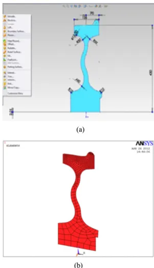
To create the 2D worn sketches, the worn curves resulted from the last step are substituted with the new ones existing on new wheels/rails. Having a precision worn 2D sketches, we match the base nodes exactly on each other in SolidWorks soft- ware. Finally, the 2D sketches of worn wheels/rails are saved as shells. Fig. 2(a, b) shows a pre-meshed, and a meshed shell of a wheel prepared in SolidWorks and ANSYS, respectively from left to right [10].
For the next step, the cultivated shells are imported to ANSYS software by which we approach the meshing process.
Even though, meshing action can be done in LS-DYNA, ANSYS results in tidier and more qualified elements.
Indeed after meshing the shells, the 3D meshed models of rails and wheels are produced by extruding and revolving the shells, respectively.
As the final step, we apply LS-DYNA explicit software in order to simulate the rolling contact. Before preparing the roll- ing contact conditions, since the major aim of the paper is to investigate the shear stress conduct in the worst utilization of the system, the critical characteristics of subway usage should be determined. Table 2 shows some of the characteristics applied in the simulation process based on the real utilization of the Tehran subway system, particularly in Track 2.
While a train passing a curve, the contact forces will be more destructive and therefore, the contact phenomenon is surely more crucial to be discussed in this situation. Track 2 of the Tehran subway system possesses a very sharp curve, so all simulations have been approached in the worst utilization and in the worst curve of the track, 190 meters.
To simulate the rolling contact in LS-DYNA, first the posi- tion of the rail and its boundary conditions are determined. The rail inclination tangent which is 1/40 is approached and then the rail becomes fixed by some nodes existing on the rail’s base. Wheel, on the other hand, is free in every six aspects, but
Table 1 The selected worn wheel/rail couples by logged distanceThe worn wheel/
rail couples
Logged distance (Km) Wheel flange thickness (mm) Worn wheel Worn rail
#1 81430 122000 31
#2 152320 227000 29
#3 175000 262000 27
#4 197500 298000 24
Fig. 2 (a) The pre-meshed shell of the wheel, (b) The meshed shell of the wheel
limited in lateral displacement. Based on the worst curve, the amounts of angle of attack and super elevation have been cal- culated as seen in Table 2.
By accomplishing the geometry states of wheel and rail, the amounts of max speed, max axle loading, max acceleration, max lateral forces and so forth are applied to the simulated model by creating some load curves in the software. Moreover, the type of contact between wheel and rail, the precise mechan- ical properties of material, the coefficients of elasticity and plasticity, and other factors should be applied. Eventually, the simulated contact will be saved in .dyn file, and therefore it has to be carefully checked by all numeral amounts and more important by all units. Since we did not use one kind of soft- ware, the elected units in .dyn file and the dimension of wheels/rails in each step should be checked meticulously. Fig- ure 3 shows three views of wheel/rail rolling contact in LS- DYNA [11].
Fig. 3 Three views of final simulated rolling contact
4. Results and Discussion
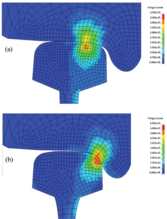
The outcomes of simulation indicate the maximum shear stresses in wheel/rail interactions for: new wheel/rail contact on straight and curved lines, and worn wheel/rail contacts in four measured profiles. The max shear stress contours for the new wheel/rail contact are shown in Fig. 4(a), 4(b).
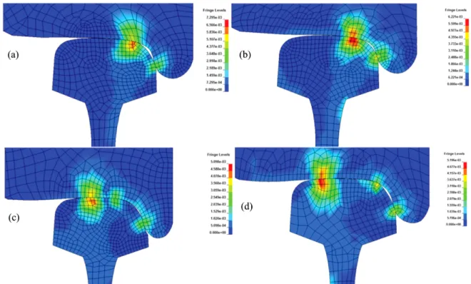
The shear stress contours related to the elected worn wheels/
rails are shown from worn number one to worn number four in Fig. 5(a) to Fig. 5(d), respectively. The simulation results reveal that, as expected, the amounts of shear stresses have more significant magnitudes in the contact patch, and moreo- ver, they are bigger in a depth just beneath the contact sur- face.
This point can be discovered by noticing the red color area in the contours which are under the contact surface.This char- acteristic of max shear stress has been already acknowledged in several theoretical and experimental studies [12]; therefore, the defects can be started in red color areas. For worn wheel/
rail interaction, generally, shear stresses decrease by logged distance as the contact surface becomes broadened; never- theless, the behavior of declension is not linear which is on account of real profile evolutions
approached by field measurements, unlike the conduct obtained based on laboratory measurements [13-15]. Indeed, it will not be even surprising that shear stresses increase in worn wheel/rail interaction in some logged distances. Table 3 shows the max shear stress magnitudes.
Table 3 Max shear stresses for new and worn wheel/rail interactions regarding the track2 of the Tehran subway sys- tem.
Table 2 The critical properties of the Tehran subway system in track 2 applied in rolling contact simulation
The worst curve (m) 190
The highest angle of attack (deg) 0.615 The highest cant angle based on UIC (mm) 150
Max speed (Km/hr) 80
Max speed in critical curve (Km/hr) 40
Max passenger per wagon 330
Max axle load (ton) 13.7
Fig. 4 Max shear stress contours in new wheel/rail contact for (a): straight line, and (b) curved line
5. Conclusion
The results demonstrate that the amounts of max shear stress obtained from field measurements, present paper, are signif- icantly considerable in worn wheel/rail interactions in pro- portional to the case that the laboratory studies are applied to find the profile evolutions.
The simulation outcomes show that approximately until mileages 81430 and 122000 km for wheel and rail respectively, the max magnitudes of shear stresses can even increase in Track 2 of the Tehran subway system, albeit not significantly.
Consequently, on account of having large magnitudes of max- imum shear stresses in worn profiles, definitely the defects resulted from shear stress will be noticeably big in worn profiles.
During the measurement studies, the shear stresses can alter from +2.8% to -33.8% in proportional to new wheel/rail con- tact in the worst curve of the track.
References
[1] P. Shriram Patil (2011) Fuel efficiency and energy conserva- tion-advantage railways, International Indexed Referred
Research Journal, 3(27), pp. 29-31.
[2] V.A. Profillidis (2006) Railway management and engineering, Ashgate Publishing Company, Burlington.
[3] S.J. Kwon, D.H. Lee, J.W. Seo (2008) Sensitivity for internal and surface defects of railway wheel using induced current focusing potential drop. Proc. of the International Conference on Advanced Nondestructive Evaluation, Busan, pp. 1322- 1327.
[4] H. Jahed, B. Farshi, M.A. Eshraghi, A. Nasr (2008) A numeri- cal optimization technique for design of wheel profiles, Wear, 264, pp. 1-10.
[5] EBI Drive 50 driver assistance system-EcoActive Technolo- gies, Bombardier Co. EBI Drive 50 Manual.
[6] X. Lu, J. Cotter, D.T. Eadie (2005) Laboratory study of the tri- bological properties of friction modifier thin films for friction control at the wheel/rail interface, Wear, 259, pp. 1262-1269.
[7] C. Chongyi, W. Chengguo, J. Ying (2010) Study on numerical method to predict wheel/rail profile evolution due to wear, Wear, 269, pp. 167-173.
[8] A. Owhadi, M.A. Rezvani, M. Ansari (2007) Monitoring of rail vehicle steel wheels with the aim of controlling wear and planning for scheduled maintenance, Journal of Transporta- tion, 4(3), pp. 249-257.
[9] Greenwood Engineering, MiniProf user's manual.
Fig. 5 The max contours of shear stresses for worn wheel/rail couples, number one (a) to number four (d) Table 3Max shear stresses for new and worn wheel/rail interactions regarding track 2 of Tehran subway system