DOI : 10.5394/KINPR.2011.35.4.317
Development of Camera-Based Measurement System for Crane Spreader Position using Foggy-degraded Image Restoration Technique
†Young-Bok Kim
†Department of Mechanical System Engineering, Pukyong National University, Busan 608-739, Republic of Korea
Abstract : In this paper, a foggy-degraded image restoration technique with a physics-based degradation model is proposed for the measurement system. When the degradation model is used for the image restoration, its parameters and a distance from the spreader to the camera have to be previously known. In the proposed image restoration technique, the parameters are estimated from variances and averages of intensities on two foggy-degraded landmark images taken at different distances. Foggy-degraded images can be restored with the estimated parameters and the distance measured by the measurement system. On the basis of the experimental results, the performance of the proposed foggy-degraded image restoration technique was verified.
Key words : foggy-degraded, image restoration, physic-base, degradation model, experiment.
†Corresponding author, [email protected] 051)629-6197
1. Introduction
Owing to the increased number of containers transferred at terminals, the improved handling efficiency has recently been required. The handling efficiency generally depends on the processing capability of container cranes. However, undesirable sway motion of a crane spreader suspended by four flexible ropes from the top of the crane sometimes greatly degrades the processing capability(Kim et al., 2000, Lee et al., 2005, Lee et al., 2008, Park et al., 2000, Son et al., 2002). Therefore, the anti-sway system is an important component for ensuring handling efficiency(Kawai et al., 2009a).
For the development of the anti-sway system, we have proposed a camera-based measurement system that consists of two landmarks affixed to the spreader and a camera installed in the crane trolley(Kawai et al., 2009b).
The measurement system can accurately measure two sway motions and a height as the spreader position by detecting two landmarks from an input image taken by the camera.
However, under foggy weather conditions at container terminals, the contrast of the input images is drastically degraded. This degradation would prevent the measurement system from achieving accurate position measurement.
Hence, it is imperative to remove the foggy weather effect from the input images in order to make the measurement system more reliable.
To restore the contrast of foggy-degraded images, several techniques based on a physics-based degradation model have been proposed(Narashiman and Nayar, 2003, Hiramatsu et al., 2008). Narasimhan et al. restore the contrast of images using two foggy-degraded images that are taken by the same viewpoint at different conditions. Hiramatsu et al restore the foggy-degraded images taken by an on-vehicle camera, using the vanishing point of the road in the images as a reference point. However, these techniques can not be employed to the proposed measurement system because the crane and the spreader are dynamically moved in the container handling process.
In this paper, we propose a foggy-degraded image restoration technique suitable for the proposed measurement system. When we restore the contrast of foggy-degraded input images using the physics-based degradation model, its parameters should be estimated from images. Since the degradation model is defined with a distance from a camera to an object as a variable, the parameters are estimated from two foggy-degraded landmark images taken at different spreader heights. After this estimation, the foggy-degraded input image is restored by using the degradation model and the spreader height measured from the previous frame. On the basis of the experimental results, the performance of the proposed foggy-degraded image restoration technique is evaluated in terms of landmark detection and position measurement.
2. Fog Degradation Model
Foggy weather conditions have a number of small atmospheric particles. The atmospheric particles scatter light beams from a scene and the sun. This scattering causes the attenuation of the light beams of the scene taken by a camera. Additionally, the scattered light beams, called airlight, also come toward the camera. Therefore, the contrast of the input images is degraded (Narashiman and Nayar, 2003, Hiramatsu et al., 2008).
Fig. 1 shows the scheme of the degradation model. In Fig.
1, we assume that a monochrome camera is used, image data represents the intensity of a light beam. Under a foggy weather condition, the intensity of a scene point is taken into a pixel of an input image, degrading exponentially with distance from the scene point. The intensity of airlight is also taken into the pixel parallel to the light beam from the scene point. Therefore, the observed intensity at a pixel of a foggy-degraded image is defined with (1).
∞ (1) Where, is the observed intensity at a pixel of the foggy-degraded input image, is the intrinsic intensity,
∞ is the intensity of the light from the sun, is the scattering coefficient, and is the distance from the object.
The foggy-degraded image restoration using this degradation model is to calculate the . Therefore, and
∞ have to be previously estimated from foggy-degraded images before the restoration.
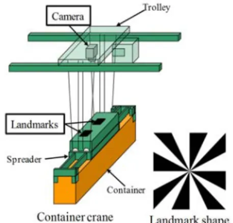
3. Measurement System for Container Crane Spreader
Fig. 2 shows a schematic diagram of the proposed measurement system installed on a container crane. This measurement system consists of two landmarks affixed to the spreader and a camera installed in the trolley. In the initial arrangement, the midpoint between landmarks is located at the image center of the camera. The landmarks used in this system have a radial pattern that consists of alternating white and black regions separated by lines intersecting at the center, as shown in the right side of Fig.
2. This shape allows the proposed measurement system to detect the central position in an input image captured at an arbitrary spreader height.
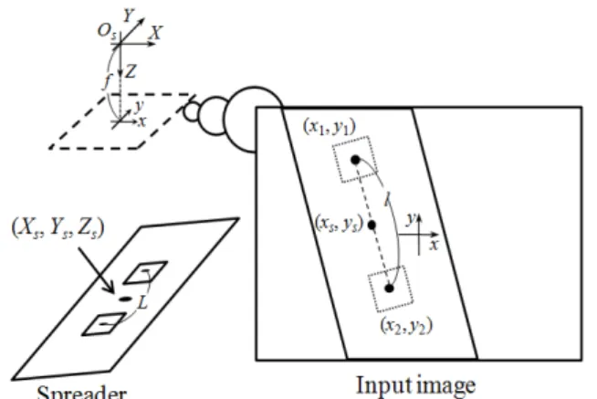
Fig. 3 schematically shows the position measurement for the spreader. In the proposed measurement system, the
midpoint between landmarks is defined as the measured point . Where and represent the horizontal and vertical displacements from the initial arrangement, represents the spreader height from the trolley. The measurement of the position is based on the central positions of two landmarks and in an input image taken by the camera, which are detected by template matching. From these central positions, the distance between landmarks, , and the midpoint of landmarks in an input image are calculated using (2) and (3).
Fig. 1 Scheme of the fog degradation model
Fig. 2 Schematic diagram of proposed measurement system
(2)
(3)Then, is calculated using (4) from the ratio of to the actual distance between landmarks .
(4) Here, is the pixel size and is the focal length of the camera.Fig. 3 Schematic diagram of position measurement for the spreader
4. Foggy-Degraded Image Restoration using Distances
To restore foggy-degraded input images using the physics-based degradation model that is represented with (1), we have to estimate the scattering coefficient and the light intensity ∞ from the sun. Considering the container handling process, we employ an estimation technique that is based on two foggy-degraded images captured at different spreader heights.
First, a variance of a landmark image that is a partial image of an input image taken at a certain spreader height
can be considered with (5).
(5)
Where, is the size of the landmark image (width × height) and is the variance of the intrinsic intensities on the landmark image(Mori et al., 2007). From (5), the variances on the landmark images taken at different spreader heights, and , are given by,
(6)
(7)
By using (6) and (7), can be estimated by,
(8)
Second, averages of the landmark images at and are also considered from (1).
∞
(9)
∞
(10) By using (6) and (7), ∞ can be estimated by,∞
(11)
Although the ∞ can be estimated with a pair of intensities of a pixel in two foggy-degraded landmark images, we use the average considering the influence of undesirable noises. Since the crane spreader is usually rolled up and down in the container handling process, two foggy-degraded landmark images are easily obtained. And the spreader height can be measured with (2)-(4) by automatically or manually detecting two landmarks from the foggy-degraded input image. Therefore, this estimation technique can be applied to the proposed measurement system.
The foggy-degraded image restoration using the physics-based degradation model is processed before landmark detection. From (1), the restored intensity of a foggy-degraded input image is given by (12),
∞ (12)
Here, as the distance , we use the previous spreader height , which is calculated from the previous input image. The previous is actually different from the actual height where the foggy-degraded input image is taken, but the spreader height is gradually changed in the container handling process. Hence, we regard the previous as the actual height.
5. Experiment
To evaluate the performance of the proposed foggy-degraded image restoration technique, we conducted an experiment with foggy visibility. In the experiment, we placed a camera and a movable board assumed as the crane spreader into a clear and sealed box. Additionally, a humidifier was installed into the box, which is used to make the inside visibility of the box foggy. Then, we took 450 input images while actuating the humidifier and moving the
Frame 150 Frame 450 Frame 150 Frame 450 (a) Landmark detection without image restoration (b) Landmark detection with image restoration
Fig. 5 Experimental results for landmark detection spreader from 590 mm to 1534 mm of the distance with
some stationary condition. Table 1 and Fig. 4 show parameters of the proposed measurement system, foggy-degraded input images and the template, respectively.
From comparison of the visibility of the spreader in Frame 1 with one in Frame 450, the visibility was clearly degraded according to the spreader height.
Fig. 4 Input images and template
Table 1 Parameters of measurement system Input image size
(width×height) 640×480 pixels
Template image size
(width×height) 34×34 pixels
Focal length : 12 mm
Pixel size : 0.0074 mm/pixel Distance between
landmarks : 88mm
Table 2 Estimation results for the parameters
Parameter Estimated value
×
∞
In the experiment, we estimated the scattering coefficient and the light intensity ∞ from the sun with upper landmark images that were manually extracted from Frame 1 and Frame 450. Table 2 shows the estimation results for the parameters. Then, while restoring the input images based on the estimated parameters, the
measurement system detected two landmarks and measured the spreader position.
Fig. 5 shows the experimental results for the landmark detection in Frame 150 and Frame 450 of the foggy-degraded input images. The detected landmark positions are depicted as rectangles in the input images. For comparison, the results without the proposed image restoration technique are shown in Fig. 5(a), where the landmark detection failed due to poor visibility. In contrast, the landmark detection with the proposed restoration technique succeeded in all input images, as shown in Fig.
5(b).
Fig. 6 shows experimental results for the spreader position obtained from the measurement system with the proposed image restoration technique. Since the landmark detection succeeded in all input images, the position measurement also succeeded in all input images.
Additionally, no large fluctuation in the measured values is observed in stationary conditions. These results mean that the proposed foggy-degraded image restoration technique allows our measurement system to successfully measure the spreader position.
Fig. 6 Experimental results for spreader position measurement with the proposed image restoration
6. Conclusion
A foggy-degraded image restoration technique for the spreader position measurement system has been proposed.
The proposed restoration technique is based on a physics-based model representing the degradation of the image intensity under foggy weather conditions. The model parameters are estimated by using variances and averages of two foggy-degraded landmark images. By using the estimated parameters and a measured spreader height, the measurement system restore the foggy-degraded input image. From the experimental results, it is clear that the proposed foggy-degraded image restoration technique allows the proposed measurement system to successfully measure the spreader position under foggy condition. As future works, we will evaluate the accuracy of the measurement system with the proposed under a foggy weather condition.
References
[1] Hiramatsu T., Ogawa T., and Haseyama M.(2008), “A Kalman Filter Based Restoration Method for In-vehicle Camera Images in Foggy Conditions”, Proc. of IEEE International Conference on ICASSP 2008, pp. 1245~
1248.
[2] Kawai H., Kim Y.B., and Choi Y.W.(2009a), “Anti-sway System with Image Sensor for Container Cranes”, Journal of Mechanical Science and Technology, Vol. 23, No. 10, pp. 2757~2765.
[3] Kawai H., Choi Y.W., Kim Y.B., and Kubota Y.(2009b),
“Measurement System Design for Sway Motion Based on Image Sensor”, Networking, Sensing and Control, ICNSC'09. International Conference, pp. 185~188.
[4] Kim Y.H., Lee Y.J., Lee J.W. and Lee K.S.(2000),
“Performance Analysis and Design of a High Efficiency Gantry Crane”, Journal of Navigation and Port Research, Vol. 14, No. 4, pp. 395~406.
[5] Lee S.J, Park H. abd Hong G.S.(2005), “Sliding Mode Control of Container Crane”, Journal of Navigation and Port Research, Vol. 29, No. 8, pp. 747~753.
[6] Lee S.R., Ahan J.G., Lee Y.H., Son J.G. and So M.O.(2008), “RTGA Based States Observer Design of Container Crane Considered with Design Specification”, Journal of Navigation and Port Research, Vol. 32, No.
10, pp. 851~856.
[7] Mori K., Takahashi T., Ide I., Murase H., Miyahara T., and Tamatsu Y.(2007), “Recognition of Foggy
Conditions by In-vehicle Camera and Millimeter Wave Radar”, Intelligent Vehicles Symposium, 2007 IEEE, pp.
87~92.
[8] Narasimhan S. G. and Nayar S. K.(2003), “Contrast Restoration of Weather Degraded Images”, IEEE Trans.
Pattern Analysis and Machine Intelligence, Vol. 25, No.
6, pp. 713~724.
[9] Park C.H., Park K.T., Kim D.H. and Shin Y.J.(2000),
“A Study on Sway Control of Containers of Yard Crane”, Proceedings of the 2000 Autumn Conference of Korean Institute of Navigation and Port Research, pp.
143~151.
[10] Son D.S., Lee J.W., Mhin J.T. and Lee K.S.(2002), “A Study on Anti-sway of Crane using Neural Network Predictive PID Controller”, Proceedings of the 2002 Spring Conference of Korean Institute of Navigation and Port Research, pp. 219~227.
Received 2 June 2011 Revised 28 June 2011 Accepted 28 June 2011