Online ISSN: 2288-7253 DOI: http://dx.doi.org/10.14579/MEMBRANE_JOURNAL.2014.24.3.177
다공성 금속 지지체에 제조된 실리카 분리막의 기체 투과 특성
이 혜 련⋅서 봉 국†
한국화학연구원 그린정밀화학연구센터
(2014년 1월 8일 접수, 2014년 6월 19일 수정, 2014년 6월 24일 채택)
Preparation and Gas Permeation Properties of Silica Membranes on Porous Stainless Steel-Tube Supports
Hye Ryeon Lee and Bongkuk Seo
†Research Center for Green Fine Chemicals, Korea Research Institute of Chemical Technology (KRICT), 895-4 Yugok-dong, Jung-gu, Ulsan 681-802, Korea
(Received January 8, 2014, Revised June 19, 2014, Accepted June 24, 2014)
요 약: 본 연구에서 고투과도를 갖는 실리카 분리막은 콜로이달 실리카 졸과 고분자형 실리카 졸 두 가지를 DRFF법과 SRFF법으로 다공성 금속 지지체 위에 코팅하여 제조되었다. 실리카 졸은 졸-겔법으로 테트라에톡시실란(TEOS)에 의하여 제 조되었고, 각각의 졸은 동적광산란법(DLS), 전계방사 주사전자현미경(FE-SEM), 질소 흡착법 등을 이용하여 그 특성을 평가 하였다. 다공성 금속 지지체위에 콜로이달 실리카 졸로 중간층을 형성하여 치밀한 구조의 실리카 층을 형성한 후 그 위에 분 리층으로 고분자형 실리카 졸을 코팅하여 핀홀을 줄이는 방법으로 기체분리용 분리막을 제조하였다. FE-SEM으로 분리막의 코팅 층을 분석한 결과 분리층은 중간층보다 침밀한 구조를 가지고 있음을 확인하였고 기체투과 결과 수소 투과도 (6.63-9.21) × 10
-5mol⋅m
-2⋅ s
-1⋅ Pa
-1분포를 보였다.
Abstract: Silica membranes with high permeability were prepared using colloidal and polymeric silica sols on a porous stainless steel-tube support by a DRFF and SRFF method. Silica sols were derived with tetraethylorthosilicate (TEOS) by sol-gel method and analyzed with DLS, FE-SEM, and N
2adsorption. The coating of the intermediate layer with colloidal silica sol on the stainless steel-tube support led to a denser surface morphology of the membrane along with a considerable reduction in the number of surface defect. As the polymeric silica sol enclosed the colloidal silica sol with spherical par- ticles during the SRFF method, the separation-layer-coated silica membrane showed a denser surface than the intermediate layer. Moreover, the silica membranes showed high hydrogen gas permeability of (6.63-9.21) × 10
-5mol⋅m
-2⋅s
-1⋅Pa
-1with low H
2/N
2perm-selectivity (2.9-3.1) at room temperatures.
Keywords: Sol-gel technique, SiO
2sol, Mesoporous membrane, Gas separation
1. Introduction
1)
Microporous silica membranes, which are generally prepared by chemical vapor deposition (CVD)[1-3] or sol-gel technique[4-8] with silica precursors such as TEOS on the ceramic supports, have a great potential for hydrogen gas separation. TEOS-derived silica mem-
†
Corresponding author(e-mail: [email protected])
branes consist of amorphous silica networks in the range of 0.3 to 0.5 nm and show high hydrogen se- lectivity and quite low hydrogen gas permeability[1-11].
In order to increase the hydrogen gas permeation, pore-size control of the microporous silica membranes was first proposed by Raman and Brinker in 1995 as the “template” technique[12]. Using the “template”
technique, pore-size-controlled silica membranes were
developed using structured alkoxides such as methyl-
triethoxysilane (MTES)[12-14], methacryloxypropyltrimeth- oxysilane[16], and alkyltriethoxysilanes[17] by a sol-gel method and using structured alkoxides that have a sin- gle Si atom with phenyl or alkyl functional groups (methyl, propyl, etc.), by the CVD method[18-21].
A few research groups have proposed the use of a new type of Si precursor, i.e., a bridged alkoxide such as bis (triethoxysilyl) ethane (BTESE, ≡Si-C-C-Si≡
unit) or bis (triethoxysilyl) methane (BTESM, ≡ Si-C-Si≡ unit). A research group at the University of Twente, Netherlands, developed hybrid silica mem- branes having excellent hydrothermal and acid stability by sol-gel technique using a BTESE and BTESM for pervaporation[22-24]. Tsuru (2008) proposed the use of an organic functional group as a “spacer” to control the pore size of silica membranes for gas separation, i.e., the “spacer” technique[9,25-27], where ≡Si-R-Si≡
unit is considered to be the minimum unit of silica networks, thus resulting in a loose structure.
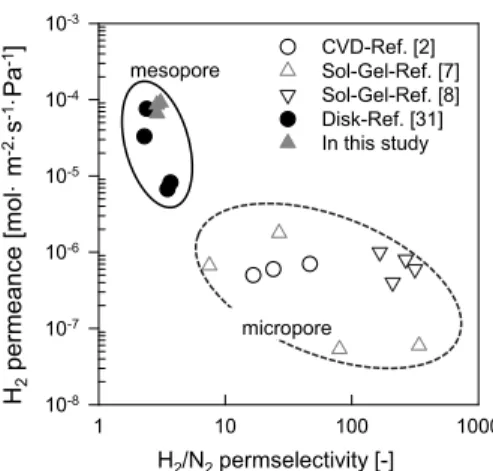
Although pore-size-controlled membranes of micro- porous silica network on the porous α-alumina support showed loose structure and high hydrogen gas perme- ability in the range of 10
-6to 10
-5mol⋅m
-2⋅s
-1⋅Pa
-1, their permeability was extremely low and their utilization in industries was difficult[17,29]. However, the meso- porous membranes show high permeability with the Knudsen permeation behavior[30,31]. Therefore the meso- porous silica membranes with the Knudsen permeation behavior are expected to be suitable for industrial appli- cation of membrane processes. D.-W. Lee et al. at KRICT prepared mesoporous silica membranes on a stainless steel-disk support using colloidal silica sol with 100 nm-sized particles, via a dipping-rolling-freezing-fast drying (DRFF) and soaking-rolling-freezing-fast drying (SRFF) method[31]. The membranes supported with the stainless steel disk showed hydrogen gas permeance of (6.7-8.2) × 10
-6mol⋅m
-2⋅s
-1⋅Pa
-1, with the H
2/N
2permselectivity value of 3.5-3.7. The obtained permse- lectivity value approached the theoretical H
2/N
2selectivity value of 3.74 for the Knudsen diffusion mechanism.
In this study, silica membranes on porous stainless steel-tube support were prepared using colloidal and pol-
ymeric silica sols by the DRFF and SRFF method. The silica sols were prepared with alkaline catalyst and acid catalyst, respectively, and evaluated by dynamic light scattering (DLS), field-emission scanning electron micro- scope (FE-SEM), and N
2adsorption. FE-SEM and perm- porometer were also used to observe the variation in morphology and characteristics of the membrane surface after single gas permeation test at room temperature.
2. Experimental
2.1. Preparation of silica sols and membranes Silica sols were prepared by the hydrolysis and con- densation of TEOS with ammonia and hydrochloric acid as alkaline and acid catalysts, respectively. The concentration of ammonia was in the range from 0.71 to 5.32 wt% with pH 9-12, while that of hydrochloric acid was 0.5 wt% with pH 3[7,30,31]. Specific amounts of TEOS and water in ethanol with ammonia and hy- drochloric acid catalysts were stirred at 50 °C for 4 h.
TEOS/water ratio was 1 : 60, and the concentration of TEOS was maintained at 7.0 wt%. All the chemicals were used without further purification in this study.
A porous stainless steel-tube (O.D. = 10.0 mm, 316 L SUS, Mott corp. USA) was used as the support for porous silica membranes. These membranes were pre- pared using colloidal silica and polymeric silica sols by a DRFF and SRFF method[30,31]. The complete pro- cedure or preparing silica membranes on the support is shown in Fig. 1. The support was dipped into colloidal silica sol with 100 nm or 300 nm-sized particles for 30 s, and was rolled out with a urethane rolling sheet in order to eliminate silica cake layer formation on the substrate. Subsequently, the substrate was frozen in liq- uid nitrogen for 30 s, followed by fast drying of the substrate for 30 s on a hot plate heated to 250°C. The DRFF process was repeated seven times to cover large pores, and the substrate was then fired at 700°C for 30 min in atmospheric air.
In order to minimize the number of defects on the
membrane surface, additional infiltration of the poly-
meric silica into the membrane by means of the SRFF
Fig. 1. Porous silica membranes on stainless steel-tube sup- port preparation procedure by a DRFF and SRFF method.
Fig. 2. A schematic diagram of experimental apparatus re- quired for gas permeation measurement.
Mem- brane
Mean flow pore
diameter [µm] Coating materials Substrate Intermediate
layer
Intermediate layer
Separation layer
M1 0.79 0.31 300 nm -
M2 - - 300 nm Polymeric sol
M3 - - 180 nm Polymeric sol
M4 - - 100 nm Polymeric sol
Table 1. Characteristics of Silica Membranes Prepared by Various Synthetic Methods
process was conducted. One side of the membrane was sealed and opposite side of membrane was vacuumed by a rotary vacuum pump. The membrane was dipped into polymeric silica sol, and maintained for 30 s. The soaked substrate was rolled out with a urethane rolling pin. The substrate was subsequently frozen in liquid nitrogen for 30 s, followed by fast drying for 30 s on a hot plate heated to 250°C. The SRFF process was
also repeated seven times and the substrate was fired at 700°C for 30 min in the presence of atmospheric air. The silica membranes prepared via various syn- thetic routes are listed in Table 1.
2.2. Characteristics of silica sol and membranes A DLS (Otsuka Electronics, Japan) was used for measuring the colloidal particle size after synthesis of colloidal silica sol with ammonia. The silica gel for FE-SEM (Philips XL-30S) analysis and N
2adsorption was prepared by drying the sol at 40°C in air and grinding with mortar. N
2adsorption measurements (at 77 K) for silica gel powder samples calcined at 700°C in atmospheric air were carried out using a Micromeritics ASAP 2420 instrument. Pore size distribution curves were obtained from desorption branch by using the Barrett-Joyner-Halenda (BJH) method. The morphology of silica surface and the cross sections of the substrate and membrane were measured using a PMI permporometer. The single gas permeation test was conducted after preparation of the silica membrane. Fig. 2. depicts the schematic dia- gram of experimental apparatus required for the gas per- meation measurement. Single gas permeation characteristics (He, H
2, and N
2) for silica membranes were evaluated at room temperature by using a soap-film flow meter.
3. Results and discussion
3.1. Characteristics of silica sol and gel powder
The size of the colloidal sol particles was measured
by DLS after synthesis of colloidal silica sols with am
Fig. 3. Effect of ammonia concentration on sol particle size distribution.
P/P
o[-]N
2adso rption [cm
3(S T P · g
-1]
0.0 0.2 0.4 0.6 0.8 1.0
0 20 40 60 80 100 120 140 160 180
Adsorption Desorption ( )
(a) Dried silica
P/P
o[-]0.0 0.2 0.4 0.6 0.8 1.0
0 20 40 60 80 100 120 140 160 180
Adsorption Desorption ( )
(b) Calcined silica
Fig. 4. N
2adsorption/desoroption isotherms for 300 nm size of silica gel powders (a) dried at 80 °C and (b) cal- cined at 700 °C.
monia catalyst in the range from 0.71 to 5.32 wt%
with pH 9-12. Fig. 3 shows the effect of concentration of ammonia catalyst on the colloidal sol particle size.
The particle size increased from approximately 20 nm to 300 nm due to an increase in the catalyst concentration. Fig. 4 shows the N
2adsorption iso- therms of the silica powders with 300 nm sizes that were dried and calcined at 80°C and 700°C in atmos- pheric air, respectively. The adsorption isotherms are shown as a function of P/Po, which is the relative pressure of N
2at 77 K. The silica powders dried and calcined at 80°C and 700°C using ammonia catalyst showed type IV adsorption patterns, consisting of large number of mesopores with sizes of 34 and 42 nm, respectively. In general, the basic conditions generally increased cross-linking, leading to decreased micro- porosity and a broader distribution of larger pores in silica gels; thus, silica colloidal sol was synthesized under the alkaline system as condensation kinetics were faster than hydrolysis kinetics[9]. Therefore, it can be concluded that large mesoporous silica sol was synthesized with TEOS and ammonia catalyst, as shown in Figs. 3 and 4.
The silica sol was prepared with ammonia catalyst in the range of 0.71 to 5.32 wt%, and distributed about 20 nm to 300 nm, as shown in Fig. 3. A part of silica sols were dried at 40°C in air, ground with mortar, 오
and then analyzed by FE-SEM. Fig. 5 shows the im-
ages of colloidal silica gel powders with 180 nm and
300 nm sizes. The silica particles show uniform spher-
ical shape in both figures. The sol-gel process is div-
ided into the polymeric sol-gel route and colloidal
sol-gel route. In the colloidal route, the hydrolysis and
condensation reaction is faster than that in the poly-
meric route. The rapid condensation reaction causes
particulate growth and/or formation of precipitates. On
the other hand, the hydrolysis reaction in the polymeric
route is slower, and a linear inorganic polymer is
formed. It is generally agreed that alkoxides are slowly
hydrolyzed, and entangled linear chains are formed in
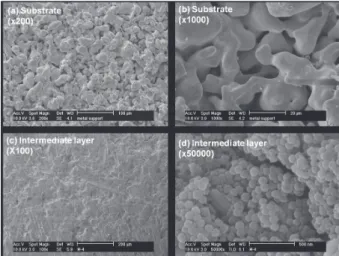
Fig. 6. FE-SEM images of surface section for support and in- termediate-layer-coated silica membrane for M-1 membrane.
Fig. 7. SEM images of surface and cross section for sepa- ration-layer-coated silica membrane (M-4) with polymeric silica sol.
Fig. 5. SEM images of 180 nm and 300 nm silica gel powder prepared by sol-gel method.
the acid systems, while the hydrolysis reaction is rela- tively fast. Further, it is easy to form colloidal sols in alkaline solutions[7,9]. Finally, from the DLS and FE-SEM analysis, it is confirmed that the spherical silica particles were synthesized in the ammonia sys- tem, as shown in Figs. 3 and 5.
3.2. Characteristics of silica membranes The intermediate layer on the stainless steel-tube support membranes was prepared using colloidal silica sols by means of the DRFF and SRFF method. Fig. 6 shows SEM images of tube support surface and inter- mediate-layer-coated silica membranes (M-1). As shown in Fig. 6 (a) and (b), for the stainless steel-tube support showing rough and large pores, a mean flow pore diameter of 0.79 µm was measured by PMI permporometer. In comparison to the support, after the membrane was coated with the intermediate layer, the surface of the membrane was denser and the number of surface defects decreased considerably, as shown in Fig. 6 (c). After coating of the intermediate layer, the separation layer was coated with polymeric silica sol by means of the DRFF and SRFF method. Fig. 7 shows SEM images of M-4 membrane surface and the cross section of the separation layer after coating with polymeric silica sol. The separation-layer-coated silica membrane (M-4) had no defects or pinholes on the surface section, unlike the intermediate-layer-coated silica membrane with silica colloidal sol having 300 nm-sized particles. Under high magnification (Figs.
6(d) and 7(b)), it was observed the silica colloidal par- ticles were aggregated and packed on the surface of
intermediate-layer-coated silica membrane. However, the surface of polymeric-sol-coated separation layer was smoothly coated and there was no colloidal particle. Since the polymeric silica sol penetrated and enclosed spherical colloidal silica sol as shown in Figs.
7 (c) and (d), separation-layer-coated silica membranes with polymeric sol are well prepared with a defect-free surface unlike the intermediate-layer-coated silica mem- brane with colloidal sol.
In addition, silica membranes were prepared with
colloidal and polymeric sol by means of the DRFF and
SRFF method, and evaluated by using He, H
2, and N
21 10 100 1000 10-8
10-7 10-6 10-5 10-4 10-3
CVD-Ref. [2]
Sol-Gel-Ref. [7]
Sol-Gel-Ref. [8]
Disk-Ref. [31]
In this study
H2/N2permselectivity [-]
H
2p e rm e an ce [m ol · m
-2·s
-1·Pa
-1]
mesopore
micropore

![Fig. 3. Effect of ammonia concentration on sol particle size distribution. P/P o [-]N2adsorption [cm3(STP ·g-1]0.00.20.4 0.6 0.8 1.0020406080100120140160180AdsorptionDesorption( )](https://thumb-ap.123doks.com/thumbv2/123dokinfo/5470345.440024/4.892.502.761.139.705/fig-effect-ammonia-concentration-particle-distribution-adsorption-adsorptiondesorption.webp)