차량에 적용 가능한 T-DMB/GPS/Mobile 안테나의 제작과 측정
이승재*․윤중한**․이진우*
Construction and Measurement of a
T-DMB/GPS/Mobile Antenna for Vehicular Application
Seung-Jae Lee
*․Joong-Han Yoon
**․Jin-Woo Lee
*요 약
본 논문은 차량에 적용하기 위해 통합된 T-DMB/GPS/Mobile 안테나를 설계 제작하였다. T-DMB 안테나 는 선형편파와 전 방향 방사패턴을 갖도록 하기 위해 변형된 미앤더 형태의 마이크로스트립 패치를 사용하여 설계하였다. GPS 안테나는 원형편파와 전 방향성 방사패턴을 갖도록 하기 위해 패치 안테나에 슬롯을 삽입 하여 설계되었다. 또한 모바일 안테나는 여러 가지 휴대 단말기 주파수 대역인 GSM (880~960 MHz), AMPS (824~894 MHz), DCS (1710~1880 MHz), PCS (1850~1990 MHz), UMTS (1920~2170 MHz) 등에 서 동작될 수 있도록 변형된 G 형태의 패치 안테나를 사용하여 설계되었다. 측정결과, VSWR 1:2.5에서 만족 하는 임피던스 대역폭은 시뮬레이션 결과와 비슷한 경향을 나타내었다. 또한 2D 그리고 3D 방사패턴과 이득 에 측정결과가 제시되고 논의되었다.
ABSTRACT
This paper presents the design of a novel integrated T-DMB/GPS/Mobile antenna for vehicular application. The T-DMB antenna is designed with a modified meander-type microstrip patch providing linearly a polarized broadside radiation pattern. The GPS antenna is designed with an inserted slot in the patch antenna providing circularly polarized broadside radiation pattern. The Mobile (GSM, AMPS, DCS, PCS, UMTS, etc.) antenna is designed as a modified G-type patch antenna providing multi-band operation.
Experimental results indicate that the impedance bandwidth (VSWR 1:2.5) of the proposed T-DMB /GPS/Mobile antenna satisfactorily matches that of the simulation results. The 2D and 3D radiation patterns and gains according to the results of the experiment are also presented and discussed.
키워드
T-DMB/GPS/Mobile antenna, multi-band operation, vehicle application T-DMB/GPS/Mobile 안테나. 다중밴드 동작, 차량 응용
* HCT 안테나 그룹([email protected])
** 교신저자 : 신라대학교 전자공학과([email protected])
접수일자 : 2011. 08. 18 심사(수정)일자 : 2011. 09. 29 게재확정일자 : 2011. 10. 12
Ⅰ. INTRODUCTION
The rapid development of electronic engineering has improved the concept of transportation via automobiles which were once completely dependent on a mechanical structure through diversification and a hyper functional structure. Owing to this technical development, numerous communication devices, such as mobile phones, FM multiplex broadcasting devices, satellite phones, DSRCs, terrestrial digital broadcasting devices, and satellite digital broa- dcasting devices, can now be installed in auto- mobiles. Antennas for automobiles, which are essential for the realization of automobile commu- nication, are the most important parts that should be installed in every automobile so it can transmit and receive one- or two-way communication during operation. Antennas play a key role in commu- nications not only inside and outside an automobile but also between automobiles. Due to the increasing number of radio services using different frequency bands, the number of necessary antennas for a vehicle has also increased. Since antennas for different services usually need to be installed separately, the placement of various antennas to guarantee optimum performance for each service in a vehicle has posed a problem to users.
In the past, large external antennas were installed on automobiles. These were screw-shaped, helical-type winding-coil antennas. The disadvantage of these antennas is that they have an individual communication function. At present, shark antennas, which are placed on the rear part of automobiles, are largely being used as automobile antennas. The additional integrated design function of a T-DMB antenna and its radio reception may have an advantage, but they cost high and have limited reception, unlike external antennas. At present, as different multimedia equipment can now be integrated into one terminal, antennas are also being developed technically to provide a simple multimedia
communication environment using drivers for multiple functions.
A remarkable trend in modern car communicati- on is that all available applications, such as T-DMB, GPS, and mobile applications, are merged into a single terminal. Especially in Korea, digital multimedia broadcasting (DMB) services are becoming popular. As the resonant length of the Terrestrial Digital Multimedia Broadcasting band (T-DMB, 174~214 MHz) is much longer than that of the conventional antenna, it is very difficult to utilize a T-DMB antenna. Hence, this paper studies and proposes a design for a T-DMB antenna [2]-[3].
A GPS antenna for vehicle application is also proposed and designed to generate a circular polarized antenna for GPS and ETCS [4]. Mobile bandwidths, such as Advanced Mobile Phone System(AMPS, 824~894 MHz), Global System for Mobile Communication (GSM, 890~960MHz), Digita -l Communication System (DCS, 1710~1880 MHz), Personal Communication System (PCS, 1850~1990 MHz), and Universal Mobile Telecommunication System (UMTS, 1920~2170 MHz) are necessary to communicate in vehicles. Hence, a multiband antenna for vehicle application is proposed. To meet the miniaturization and aesthetic requirements of a vehicle antenna, manufacturers are trying to come up with low profile and broadband antennas [5]-[9].
However, low profile, multiband, and integrated antenna for various services are needed.
In this document, we propose an integrated antenna which is suitable for mounting on a vehicle to access mobile, T-DMB, and GPS services. To lengthen the wavelength of T-DMB antennas, we proposed a modified meander-type antenna structure that produces a coupling effect between the lines.
To obtain the circular polarization of the GPS
antenna, we inserted a slot line and a properly
selected feeding point in the patch. This mobile
antenna that operates on various bands is designed
with a modified G-type structure. Details of the proposed antenna design and experimental results are described below.
Ⅱ. ANTENNA DESIGN
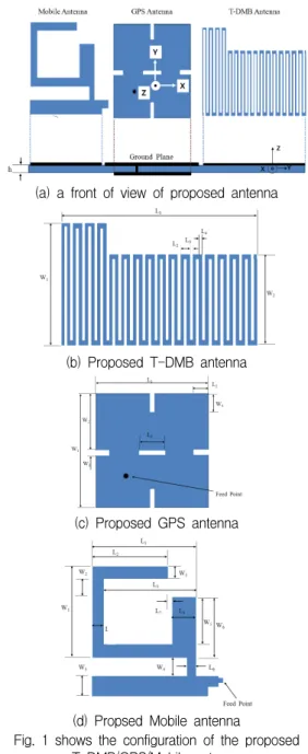
Fig. 1 shows the configuration of the proposed T-DMB/GPS/Mobile antenna. The cross section and front view of the proposed integrated T-DMB/
GPS/Mobile antenna is shown in Fig. 1(a). The total size of the proposed antenna in the study is 1.0-mm thick with 215×75mm
2FR4 substrate, which is a reasonable size for practical vehicle application. The proposed patch antenna for vehicle application consists of three parts: the T-DMB antenna, GPS antenna, and Mobile antenna. The T-DMB patch antenna is located at the right part of the proposed structure, the GPS patch antenna is located at the center, and the mobile patch antenna is located at the left part. Also, T-DMB and Mobile patch antenna is set at the top layer, and the GPS patch antenna is at the bottom layer. In case of T-DMB and Mobile antenna, ground plane at the opposite of the patch antenna is removed to achieve good radiation pattern. As for the GPS antenna, the ground plane of the opposite of the patch is not removed to enhance isolation between mobile and GPS. Also, coaxial feeding method is used by the GPS antenna and microstrip line feeding is used by T-DMB and Mobile antenna. To reject of the isolation between the ports, enough separation distance and ground plane are got.
The front view of the proposed T-DMB/GPS/Mo -bile antenna is shown in Figure 1(b), 1(c), and 1(d), respectively. Figure 1(b) shows the proposed patch antenna for T-DMB application.+ This T-DM-
B (174~210MHz) patch antenna is designed with a modified meander-type structure to lengthen the strip line and product coupling effect between the
lines at given dimensions to provide a linearly polarized broadside radiation pattern. Also, we used L component to matching the impedance of the operating band. The size of the T-DMB patch antenna is 120×55mm
2.
(a) a front of view of proposed antenna
(b) Proposed T-DMB antenna
(c) Proposed GPS antenna
(d) Propsed Mobile antenna
Fig. 1 shows the configuration of the proposed
T-DMB/GPS/Mobile antenna
Figure 1(c) shows the proposed patch antenna for GPS application. The GPS (1575.42±1.023MHz) patch antenna is designed with an insertion slot in the patch antenna to provide a circularly polarized broadside radiation pattern. The GPS patch antenna is inserted in the slot and has a properly selected feeding point in the patch to generate circular polarization. The length and width of the slot matches the input impedance of the GPS patch antenna to that of a fixed coaxial feed. The size of the GPS patch antenna is 43×43mm2. Figure 1(d) shows the proposed patch antenna for mobile application. The Mobile (GSM, AMPS, DCS, PCS, UMTS, etc.) antenna is designed as a modified G-type patch antenna providing multi-band operation. The length and width of the strip line has been analyzed properly to match the input impedance of this mobile patch antenna.
To obtain the optimal parameters (lines, lengths, gaps) of the proposed T-DMB/GPS/Mobile antenna, HFSS [10], which is a full-wave commercial EM software capable of simulating finite substrate and finite ground structure, was used to identify the ideal geometry for vehicle antenna. The dimensions of the mobile antenna are set as follows: (in case of T-DMB patch antenna) L1 = 120 mm; L2 = 3.0 mm; L3 = 1.0 mm; L4 = 1.0 mm; W1 = 75 mm;
W2 = 55 mm, (in case of GPS patch antenna) L1 = 43 mm; L2 = 20.8mm; L3 = 1.1 mm; W1 = 42.7 mm; W2 = 5 mm; W3 = 3 mm; W4 = 6.9 mm, (in case of Mobile patch antenna) L1 = 24.5 mm; L2 = 18 mm; L3 = 21. 5 mm; L4 = 6 mm; L5 = 3 mm;
L6 = 2 mm; L7 = 0.5 mm; W1 = 22.5 mm; W2 = 5 mm; W3 = 3 mm; W4 = 6 mm; W5 = 11.5 mm W6
= 14.5 mm.
Ⅲ. FABRICATION & MEASUREMENT
Based on the simulation results, the proposed T-DMB, GPS, and mobile patch antenna is created
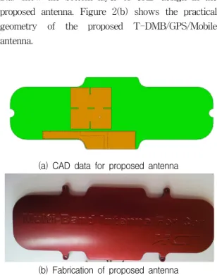
and tested using the Agilent Technologies E8362B Vector Network Analyzer, with far-field patterns and gain within a compact range, obtained from HCT Co. Ltd. and Korea Martin University. Figure 2(a) show the bottom layer of CAD design in the proposed antenna. Figure 2(b) shows the practical geometry of the proposed T-DMB/GPS/Mobile antenna.
(a) CAD data for proposed antenna
(b) Fabrication of proposed antenna Fig. 2 shows the practical geometry of the proposed
T-DMB/GPS/Mobile antenna.
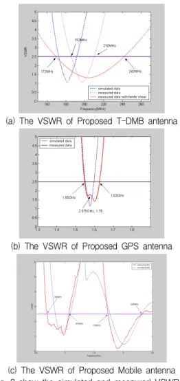
Figure 3(a), 3(b), and 3(c) show the simulated
and measured VSWR of the proposed T-DMB,
GPS, and Mobile patch antenna, respectively. The
results show a satisfactory match between the
antenna’s measurement and the data from the
simulation obtained from Ansoft HFSS. The cured
trend is behaved well over the whole operating
bands. Based on the VSWR 1:2.5 ( -7.5 dB return
loss bandwidth), which is acceptable for each
application, the impedance bandwidth of this
T-DMB, GPS, and Mobile antenna should be about
70 MHz (172~242MHz), 80 MHz (1550~1630MHz),
and 380 MHz, 625MHz (690~1070 MHz, 1705~2330
MHz) respectively, covering the all T-DMB
(1576.4~1574.4 MHz), and all existing mobile bandwidths (824~960MHz, 1710~2170MHz).
(a) The VSWR of Proposed T-DMB antenna
(b) The VSWR of Proposed GPS antenna
(c) The VSWR of Proposed Mobile antenna Fig. 3 show the simulated and measured VSWR of
the proposed antenna
In particular, the bandwidth of the designed T-DMB patch antenna, is only 18MHz (192~
210MHz), which does not cover the all T-DMB bandwidths. In figure 1(b), it is shown that the amount of inductance is not sufficient to match wider because the length of the strip line is very short and the capacitance between the lines increases. However, ferrite sheets have been proven
to increase both the stored magnetic energy and the amount of inductance [11]. Thus, a ferrite sheet has used to provide sufficient inductance to match broad in this study. From the test result, we obtain the satisfactory measured data.
Fig. 4 The measured isolation between GPS and mobile ports
The measured isolation between GPS and Mobile ports is given in Fig.4. According to Fig. 4, within the frequency band covering GPS and Mobile services, the isolation between the two feeding ports is higher than -20dB. This good isolation behavior is probably because GPS and Mobile ports are separated far enough to prevent any significant energy coupling between the two ports. Also, GPS and Mobile ports are separated enough to block the signal around the ground plane of the GPS antenna.
The measured isolation between the T-DMB and GPS or Mobile port is not presented in this doc- ument because the frequency gap between each band is far enough so that the effect between the ports is minimal.
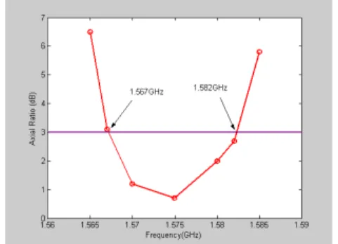
The measured axial ration against frequency the broadside direction is shown in Figure 5. The obtained CP bandwidth, defined by 3 dB axial ratio, is about 15 MHz (approximately 0.95 % with respect to 1575MHz) for GPS operation.
The radiation patterns that have been measured per
band are shown in Figure 6-8. Figure 6 show the
2D measured radiation patterns for the proposed T-DMB patch antenna. Figure 7 and 8 show the 3D measured radiation patterns for the proposed GPS and Mobile patch antenna, respectively.
Fig. 5 The obtained CP bandwidth of the proposed GPS antenna
(a) E1 174MHz (b) E2 174MHz (c) H 174MHz Fig. 6 show the 2D measured radiation patterns for
the proposed T-DMB patch antenna.
In the T-DMB antenna, radiation patterns of H, E1, and E2 are measured in the x-y, x-z, and y-z planes, respectively. Though the proposed T-DMB patch antenna does not show good omni-directional radiation patterns, the measured result shows an acceptable radiation pattern.
(a) 1560MHz (b) 1575MHz (c) 1590MHz Fig. 7 and 8show the 3D measured radiation
patterns for the proposed GPS antenna
Figure 7 shows the 3D radiation pattern at 824MHz, 1750MHz, and 2170MHz, respectively.
Good radiation patterns are observed, and the shape of radiation pattern is almost unchanging and uniform in each GPS frequency. Figure 8 shows the 3D radiation pattern at 1560MHz, 1575MHz, 1590MHz, respectively. Good radiation patterns are observed, especially for the lower operating frequencies in Fig 8(a) at 824GHz.
Fig. 8 (a) 3D radiation pattern of 824MHz
Fig. 8 (b) 3D radiation pattern of 1750MHz
Fig. 8 (c) 3D radiation pattern of 2170MHz
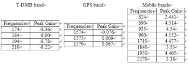
Table 1 shows the measured peak gain of the
proposed antenna for each operating frequency. For
the proposed T-DMB patch antenna, the measured
peak gain varies in a small range of about -8.0 to
-8.78 dBi. Also, the measured peak gain varies in a very small range of about -0.076 to 0.067 dBi, and its measured average gain varies in a broad range of about –5.472 to 5.37 dBi for the proposed GPS patch antenna. In case of the proposed mobile patch antenna, the measured peak gain varies in a large range of about 2.441 to 4.465 dBi, and its measured average gain varies in a broad range of about -1.952 to 1.243 dBi.
Table 1. Measured gains of proposed mobile antenna
Ⅵ. CONCLUSION
A T-DMB/GPS/Mobile antenna was proposed for vehicle applications, and its prototype operated successfully. The device was for T-DMB, GPS, and Mobile antenna designed with a modified meander-type structure, an inserted slot line, and a modified G-type, respectively. The optimum para- meters were produced by varying the width and length of the strip line and slot, and the feeding point, etc. The experiment results showed that good impedance matching was achieved. This proposed T-DMB/GPS/Mobile antenna had an impedance bandwidth (VSWR 1:2.5) of about 70 MHz (172~
242MHz) or 33.82%, 80 MHz (1550~1630MHz) or 5.03%, and 380 MHz, 625MHz (690~1070 MHz, 170 5~2330 MHz) or 43.18% and 30.98%. The proposed antenna exhibited good radiation pattern chara- cteristics and gain. The T-DMB, GPS, and Mobile patch antenna has a measured peak gain that varies from about -8.0 to -8.78 dBi, from -0.076 to 0.067 dBi, and from about 1.441 to 5.952 dBi, respectively.
The proposed antenna has an excellent potential for vehicle application.
REFERENCE
[1] T. J. Yalty, Y. Dai, and L. Lanctot, “Auto- motive antennas trends and future requ- irement”, 2001 IEEE Antennas and Pro- pagation Society International Symposium, Vol. 1, pp. 430-433, 2001.
[2] W. S. Kim, S. G. Jeon, and J. H. Choi,
“Internal Dual-band Low Profile Antenna for T-DMB/UHF Mobile Handset Applications”, 2006 IEEE Antennas and Propagation Society International Symposium, Vol. 1, pp.
4265-4268, 2006.
[3] J. H. Jang, D. H. Lee, J. P. Kim, W. M.
Seong, and W. S. Park, "A small meandered loop antenna for T-DMB applications", 2007 Antennas and Propagation Society Inter- national Symposium, Vol. 1, pp. 2459-2462, 2007.
[4] C. W. Su, C. M. Su, and K. L. Wong,
“Compact dual band circularly polarized antenna for GPS/ETC operation on vehicles”, Microwave and Optical Technology Letters, Vol. 40, No. 6, pp. 509-511, 2004.
[5] Y. T. Liu, S. W. Su, C. L. Tang, S. T. Fang, and K. L. Wong, “On vehicle low profile metal plate antenna for 900MHz operation”, Microwave and Optical Technology Letters, Vol. 40, No. 1, pp. 79-80, 2004.
[6] S. W. Su, Y. T. Liu, K. L. Wong, and C. L.
Tang, “Low profile broadband printed VHF monopole antenna for vehicular application”, Microwave and Optical Technology Letters, Vol. 42, No. 5, pp. 349-350, 2004.
[7] Y. T. Liu, S. W. Su, C. L. Tang, H. T. Chen, and K. L. Wong, “On vehicle Low Profile Metal plate antenna for AMPS/GSM/DCS/
PCS/UMTS multiband operation”, Microwave and Optical Technology Letters, Vol. 41, No.
2, pp. 144-146, 2004.
[8] M. Ali, G. Yang, H. S. Hwang, and T.
Sittironnarit, “Design and Analysis of an
r-shaped dual band planar inverted-F antenna
for vehicular application”, IEEE Trans. Vehi- cular Technology, Vol. 53, No. 1, pp. 29-37, 2004.
[9] B. Jung, J. S. Lee, M. J. Park, Y. S. Chung, F.
J. Harackiewicz and B. Lee, “TDMB/AMPS/
GSM/DCS/PCS/SDMB internal antenna using parasitic element with switching circuit”, Electronics Letters, Vol. 42, No. 13, pp.
734-736, 2006.
[10] Ansof High Frequency Structure Simulator (HFSS) Version 10.0, Ansoft Corporation, 2005.
[11] H. J. Kim, H. C. Choi, S. H. Jeon, and H. D.
Kim, “Critical coupling of a planar inverted F-antenna using a ferrite sheet”, Microwave and Optical Technology Letters, Vol. 52, No.
2, pp. 400-403, 2010.
저자 소개
이승재(Seung-Jae Lee)
현재 (주)HCT 안테나연구소 팀장
※ 관심분야 : Antenna, System Antenna, MIMO
윤중한(Joong-Han Yoon)
1992년 인하대학교 전자공학과 졸 업(공학사)
1994년 인하대학교 대학원 전자공 학과 졸업(공학석사)
2003년 인하대학교 대학원 전자공학과 졸업(공학박사) 현재 신라대학교 전자공학과 조교수
※ 관심분야 : RF & Antenna, RFID, Radar
이진우(Jin-Woo Lee)