내구성이 개선된 발전용 가스터빈 온도센서 개발에 관한 연구
이영준*ㆍ정해영**
A Study on the Step-Up Converter with the New Topology Method
Young-Jun Lee
*ㆍHai-Young Jung
**요 약
본 논문은 전력발전용 가스터빈에 사용하는 내구성이 개선된 Exhaust Gas Temperature(EGT)센서에 관한 연구이다. 가스 터빈에 적용된 EGT 센서는 고온으로 인하여 EGT 센서의 커넥터가 손상되는 문제가 있고 회 전 날개의 회전으로 인해 발생하는 심각한 진동 조건에서 센서의 물리적으로 약한 부분이 진동으로 인하여 손 상이 야기되기도 한다. 이러한 문제들은 잦은 센서 교체를 유발하고, 발전 효율을 감소시킨다. 본 논문에서는 이러한 문제점들을 분석하고 개선방법을 제시하였고, 제안된 EGT 센서의 성능을 평가하기 위해서, 고온과 진 동조건을 동시에 시험할 수 있는 복합 환경 테스트 장비를 개발하였다. EGT센서의 정확도와 응답시간을 평가 하고 열과 진동의 복합환경 시험 장비로 비교시험한 결과 기존 센서는 탄화문제가 발생하였지만, 제안된 센서 는 이러한 문제가 해결된 것을 확인하였다.
ABSTRACT
In this study, the problem is analyzed, and methods of improvement are presented. For evaluating the performance of the proposed EGT sensor, a complex environment test equipment has been developed to test both high temperature and vibration conditions at the same time. This equipment evaluates the accuracy and response time of the EGT sensor. In the results of the comparison test of the complex environment test equipment of heat and vibration, the existing sensor showed a carbonization problem, and the proposed sensor showed no problem. Therefore, it is expected that the improved EGT sensor will be able to be applied to various industrial fields, including gas turbines for power generation.
키워드
Durability, EGT (Exhaust Gas Temperature) Sensor, Gas turbine sensor, Thermocouple (TC) 내구성, EGT 센서, 가스터빈 센서, 열전대
* 교신저자 : 세명대학교 소방방재학과 ㆍ접 수 일 : 2020. 10. 22 ㆍ수정완료일 : 2020. 11. 19 ㆍ게재확정일 : 2020. 12. 15
ㆍReceived : Oct. 22, 2020, Revised : Nov. 19, 2020, Accepted : Dec. 15, 2020 ㆍCorresponding Author : Hai-Young Jung
Dept. Fire and Disaster Prevention, Semyung University Email : [email protected]
Ⅰ. Introduction
The major issue of the latest energy policy can
be summed up by the nuclear phase-out, the reduction of coal-fired power generation, and the expansion of renewable energy. In considering each
http://dx.doi.org/10.13067/JKIECS.2020.15.6.1175
Fig. 1 Sensors used in a gas turbine in electric power plants
of the three objectives, it is clear that they are in line with the global trend of transitioning to sustainable energy sources and reducing greenhouse gas emissions. However, the problem is that these goals are not only very difficult to achieve at the same time but can sometimes be at odds with each other. Natural gas is highlighted as a realistic alternative to this energy source[1-3].
To ensure the safety of gas turbine power generation, hundreds of different sensors are installed inside the gas turbine as shown in Fig. 1, and these sensors require high reliability in the severe conditions of temperature, pressure, and vibration. Among these conditions, the temperature is used as an input to the controller of the gas turbine in order to control the amount of fuel according to the volume of incoming air to the combustion chamber. Excessive fuel volume reduces the efficiency of power generation because the temperature of the combustion chamber exceeds the design range, resulting in damages of blades or incomplete combustion, and increases the concentration of greenhouse gases[4].
Temperature measurement sensors are divided into contact and non-contact types according to their contact methods. Contact type sensors include thermocouples, resistance thermometers, thermistors,
semiconductor thermometers, and glass thermometers, while non-contact type temperature
sensors include optical pyrometers, radiation thermometers, and optical fiber thermometers.
Among contact type temperature sensors, thermocouples are the most frequently used temperature sensors in industrial fields because they can measure temperatures with a wide range at a relatively low cost and are simple to use. In particular, K-type thermocouples are often used in thermoelectric power plants in measuring exhaust gas temperature in order to improve the operational efficiency of gas turbines. The K-type thermocouples for gas turbines are installed in the exhaust diffuser of gas turbines and are used mainly for the measurement of temperature distribution. The K-type thermocouples must be resistant to exhaust gas and high temperature for using it in gas turbines[5].
However, thermocouples used in practical
industrial fields may be damaged by heat in the
connectors and connecting cables of the
thermocouple under high-temperature conditions, or
physically weak parts of the sensor due to vibration
during its operation. This leads to frequent sensor
replacements, which reduce the efficiency of power
plants. In this paper, the problems of EGT sensors
used in gas turbine power generation were investigated and analyzed. To improve these problems, a method that improves the durability of exhaust gas temperature sensors used in gas turbine power generation is proposed for improving the durability in high temperature and vibration conditions. Also, the performance of the proposed EGT sensor was tested for its durability through establishing a complex environment test equipment with accuracy and response speed. The accuracy of the EGT sensor was evaluated by applying the international standards of ASTM E230, IEC 60584-2, and KS C1602[6-8]. The proposed EGT sensor and sensor cables were found to be safe from complex environment tests under high temperature and vibration conditions. Therefore, the proposed EGT sensor is expected to be applied to various industrial fields, including gas turbine power generation and jet engines.
Ⅱ. Theory of the EGT sensor
The EGT sensor is used as a K-type thermocouple, and the material of the thermocouple consists of two different types of metal wires. As the different metals A and B are joined to form a closed circuit and one side is cut open, the charges move proportionally to the temperature difference of the point of contact, resulting in electromotive force. This phenomenon is called the Seebeck effect, and the electromotive force generated is called Seebeck voltage. Eq.
(1) represents the conversion of the measured Seebeck voltage.
(1)
where σ is the Seebeck coefficient, T
1is the temperature measured at a test point, and T
2is the reference temperature.
For instance, if the measured temperatures of and are 620 and 20℃, respectively, the electromotive force, E, is 24.0mV because the Seebeck coefficient of the K-type thermocouple is about 40uV.
Fig. 2 (a) shows this calculation and Fig. 2 (b) represents the output characteristics of the K-type thermocouple[9].
(a)
(b)
Fig. 2 (a) Principle of a K-type thermocouple; (b) Output voltage characteristics of a K-type thermocouple for
temperatures
According to the International Standard of IEC 60584-2, the type of thermocouple is classified as E, J, K, T, N, B, S, and R depending on the material and temperature measurement range[6]. Table 1 shows the standard specification of these thermocouples[10].
The EGT sensor is used to prevent permanent damages of the parts in a gas turbine due to excessive increases in temperature and to control the temperature of the gas turbine. As shown in Fig. 3, the temperature of the gas turbine is controlled by the ratio of the amount of fuel to the air incoming. Also, the exhaust part where the EGT sensor is installed is in a high-temperature environment of about 600°C to 700°C and has severe vibration caused by the rotation of the turbine blade. Therefore, the EGT sensor should be able to withstand these harsh conditions.
The characteristics of the exhaust gas temperature
in a gas turbine according to the incoming air are
shown in Fig. 3[11].
Junction Type Advantage Disadvantage
exposed
type fast dynamic response
Vulnerable to external environments and mechanical chemical stresses
grounded
type fast dynamic response
High possibility of damages in the point of contact by heat and electrically vulnerable to
noise
ungrounded type
electrically noise-resistant and easily detectable by measuring insulation resistance in the case
of a fault
Slow dynamic response
(a) (b) (c)
Fig. 4 (a) Exposed junction type thermocouple, (b) Grounded junction type thermocouple, (c) Ungrounded junction type thermocouple Table 1. Materials, temperature ranges, and Seebeck
coefficients according to the type of thermocouple
Type
Materials of
Conductor Temperature (℃)
coefficient (σ) Positive
(+) Negative (-)
E Chromel Constantan -200 to 900 62 μV/℃
J Iron Constantan 0 to 760 51 μV/℃
T Copper Constantan -200 to 371 40 μV/℃
K Chromel Alumel -200 to 1260 40 μV/℃
N Nicrosil Nisil 0 to 1260 27 μV/℃
B Platinum(30%
Rhodium)
Platinum (6%
Rhodium) 0 to 1820 1 μV/℃
S Platinum(10%
Rhodium) Platinum 0 to 1480 7 μV/℃
R Platinum(13%
Rhodium) Platinum 0 to 1480 7 μV/℃
Fig. 3 Characteristics of the exhaust gas temperature according to the volume of incoming air
There are three types of K-type thermocouples according to the junction type. The shapes, advantages, and disadvantages in these thermocouples according to their junction types are presented in Fig. 4 and Table 2. The proposed junction type of the EGT sensor is an ungrounded junction type, and the welded point of the point of contact is separated from the cover. Therefore, this type is largely used in industrial fields because it has the advantage of recognizing a fault easily by measuring insulation resistance.
In addition, the welded point of the point of contact is stronger than the exposed junction type for both the external environment and the
mechanical and chemical stresses because the point of contact is not exposed.
Also, the external part of the thermocouple is generally connected to ground that is stronger than the grounded junction type for noise electrically.
However, this has a disadvantage of having a longer dynamic response time than the exposed and grounded junction types[12].
Table 2. Advantages and disadvantages of the thermocouple according to junction types
Ⅲ. Analysis of the problems of existing EGT sensors
The problems of the EGT sensor were analyzed based on the defective products obtained from January 2017 to January 2018 at the gas turbine of the 833MW liquefied natural gas (LNG) power plant located in Oseong-myeon, Pyeongtaek, Gyeonggi-do, Korea[12-13].
Fig. 5 shows the exhaust part of the gas turbine,
sample
No. Lifetime
(month) Phenomenon Cause
#1 8 disconnection connector
carbonization
#2 9 disconnection connector
carbonization
#3 7 disconnection connector
carbonization
#4 9 disconnection connector
carbonization
#5 8 disconnection connector
carbonization
#6 9 disconnection connector
carbonization
#7 8 disconnection connector
carbonization
#8 8 disconnection connector
carbonization
#9 9 disconnection connector
carbonization
#10 5 disconnection physical damage
Fig. 5 EGT sensors installed in the exhaust part of the gas turbine
which is set for its overhauling in order to explain the installation environment of the EGT sensor.
Twenty-seven EGT sensors are installed at 13.3°
intervals in the exhaust part of the gas turbine. A total of 10 defective samples were analyzed to determine faults of the EGT sensor.
The results of the analysis of these defective EGT sensors are shown in Table 3 and Fig. 6. In the major causes of faults, the connector damage (carbonization) caused by heat was found to be 90%, and the breakage caused by vibration was found to be 10%. The current male connector of the EGT sensor was a separator between terminals and was not damaged because it was made of a high-temperature resistant glass material.
However, the silicon rubber of the thermoset material used on the contact surface of the male connector was carbonized.
Also, the epoxy insulator of the female connector was carbonized and that causes a disconnection of the point of contact of the connector. In addition, the internal thermocouple wire of the EGT sensor and the weld area of the connector terminals showed disconnections due to vibration.
Table 3. Results of the analysis of the causes of the defective EGT sensors
(a) (b)
(c) (d)
(e)
Fig. 6 (a) Normal male connector of the EGT sensor, (b) Defective male connector of the EGT sensor, (c) Normal female connector of the EGT sensor, (d) Defective female connector of the EGT sensor, (e) The disconnection between the connector terminal and the thermocouple wire of
the EGT sensor
Ⅳ. Sensor design
4.1 Material & method
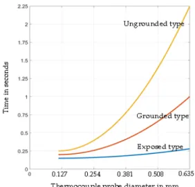
The proposed a ungrounded type EGT sensor consists of glass to metal seal connector, which has durability at a high-temperature condition, and a sheath, a metal cover of the sheath, and a stopper with a thermocouple. For the sheath containing the thermocouple, the XL K-type of OMEGECLAD was applied, and the diameter of the TC wire was 0.317mm. Fig. 7 shows the comparison of response times depending on the diameter of the thermocouple wire as a parameter of the junction types suggested by the manufacturer.
Fig. 7 Comparison of response times depending on the diameter of thermocouple wire as a parameter
of the junction types
In the fabrication process of the EGT sensor, the thermocouple wire and connector were joined by welding to withstand high temperature, and the glass to metal seal connector and the metal cover of the sheath were also joined by welding. The stopper for positioning it to the gas turbine was welded with the sheath. Finally, the empty space inside the metal cover of the sheath was filled with ceramic in
order to protect the disconnection between the thermocouple wire and the connector under vibration conditions caused by the rotation of the gas turbine blades. After curing the ceramic, the fabrication is finished by welding the ceramic filling hole. The EGT sensor cable consists of a ceramic-glass to metal seal connector and a thermocouple.
The total size of the EGT sensor is 21.24 x 496.1 (mm). The configuration and image of the proposed EGT sensor are shown in Fig. 8, and the major materials used are presented in Table 4[14-18].
Fig. 8 Configuration and image of the proposed EGT sensor and sensor cable
Table 4. Major materials used in the EGT sensor
Part name Part number
(Manufacturer) Material
Glass to metal seal male connector of the EGT sensor
S17443A000, male (Sungjin C&T)
Cover: Aluminum Positive of terminal
conductor:
Cromel Negative of
terminal conductor: Alumel
Seal: Glass
Ceramic-glass to metal seal female connector of the EGT sensor cable
S17443B000, female (Sungjin
C&T)
Cover: Aluminum Positive of terminal conductor: Cromel
Negative of terminal conductor: Alumel Seal: Ceramic-glass Metal cover of
sheath STCS-001 (i-sensor
Korea) Aluminum
Sheath
OMEGACLAD XL K-type thermocouple
(Omega)
Insulator:
Manganese oxide (MgO) TC wires: Cromel,
Alumel
Stopper STCS-002
(i-sensor Korea) Aluminum
Ceramic CNZr-01
(CNvision)
Thermosetting Zirconium oxide
powder
Welding AL T4043
(Eulji Corporation) Aluminum
Table 5. Differences in the used materials between the existing and proposed EGT sensors
Part Materials of the existing EGT sensor Materials of the proposed EGT sensor Male connectorof the EGT sensor
(Glass to metal seal and Silicon rubber are used) Temperature limit of the glass to metal seal: 1,000 Carbonization temperature of the silicon rubber: -55 ~ 300
(Only glass to metal seal is used ) Temperature limit of the glass to metal seal: 1,000
Silicon rubber is not used Insulator of the
female connector
(Only epoxy is used)
Carbonization temperature of the epoxy insulator: 200
(Ceramic and glass is used)
Temperature limit of the ceramic-glass insulator: 1,000 carbon sealing: 800
Conductors of the female and
male connectors
Positive: CuZn, gold coating Negative: CuZn, gold coating
Positive: cromel Negative: alumel
4.2 Major design differences between existing EGT sensors and the proposed EGT sensor
The main design differences of the proposed EGT sensor are designed to be stronger in heat and vibration than the existing EGT sensors. The silicon rubber used in the male connector was removed in order to increase heat resistance and to improve the carbonization issues in the silicon rubber used inside the male connector and the epoxy insulator used inside the female connector at high temperatures generated from the existing EGT sensor and sensor cable. Silicon rubber was used for the hermetic seals of the connector connections.
In the female connector, a ceramic-glass to metal seal was used, and a carbon sealing component that can be used up to 800°C is used for maintaining the hermetic seal of the connector connections. Thus, the proposed EGT sensor (temperature limit: 800°C) was designed to be about four times stronger in heat compared to the existing EGT sensor (temperature limit: 200°C). The terminal conductors of the female and male connectors used the same material as the output thermocouple wire for improving its accuracy. Table 5 and Fig. 9 show the differences in the used materials between the existing and proposed EGT sensors.
The inside of the metal cover of the sheath (the welding area of the thermocouple wires and the male connector of the EGT sensor) of the proposed EGT sensor was filled with ceramic in order to improve the disconnection of the internal thermocouple wire of the EGT sensor by vibration.
Then, the ceramic was hardened, and the ceramic filling hole was finished with welding. This is showrn in Fig. 10.
(a) (b)
(c) (d)
Fig. 9 (a) Male connector of the existing EGT sensor, (b) Connector of the proposed EGT sensor,
(c) Female connector of the existing EGT sensor cable, (d) Female connector and its cross section
of the proposed EGT sensor cable
(a) (b)
Fig. 10 (a) Curing the ceramic filling and the welding of the filling hole of the proposed EGT
sensor, (b) Cross section of the filler of the proposed EGT sensor
4.3 Test equipment design
A complex environment test equipment was designed
Description Part No. Specification Maker
Electric
furnace SLEF-005 Temperature control: up to 1,250
Size: 488 x488 x 488 mm Sunglim Industry
Thyristor power controller
PION-D3 W-035-00
3-phase, 380V, 35A (13.3 KW),
RS-485: Temp. control PIONENG
TC sensor SEN-926 K-type TC Sentech
Eng Vibration
motor &
controller WMV-20B Exciting force: 60kgf,
Vibration freq.: 60 Hz Won Hyo Industrial
Vibration
sensor LP202-1R
1-1E 4~20mA current proportional to vibration
Protection
&
reliability Instruments
Hybrid
recorder KRN1000
Input: 16 channels Remote control:
RS422/485/232 High sampling time:
25~250ms
Konics
Programmabl e logic controller (PLC)
XP-40 Touch panel input RS-232: 2 channels
RS-422/485: 1 channel LSIS
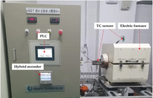
for the durability test of the proposed EGT sensor. The complex environment test equipment for the EGT sensor consists of a programmable logic controller (PLC), a hybrid recorder, a thyristor power controller, an electric furnace, a vibration motor and controller, a vibration sensor, and a TC sensor.
The electric furnace can be controlled up to 1,250°C, the exciting force of vibration can be adjusted up to 60kgf, and the vibration frequency was designed to be 60 Hz. Also, the PLC controls the temperature of the electric furnace by controlling the thyristor controller and vibration motor through receiving data from the hybrid recorder that receives input from various sensors through RS-422 and RS-232 communications.
Fig. 10 and Table 6 represent the block diagram, images, and components of the complex environment test equipment for testing the durability of the EGT sensor.
Table 6. Specification of the complex environment test equipment of the EGT sensor
Fig. 11 Block diagram of the complex environment test equipment of the EGT sensor
Fig. 12 Configuration image of the complex environment test equipment of the EGT sensor
Ⅴ. Experiment & Results
5.1 Accuracy test results
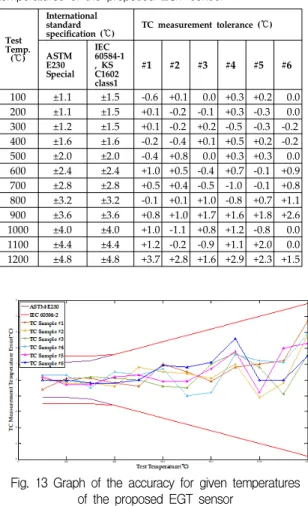
The proposed EGT sensor was tested by a public certification testing agency. The proposed accuracy of the EGT sensor was tested for six samples at intervals of 100°C to 1,200°C. The according to the K-type thermocouple of the international standards, the grades are classified as the Special and Standard in ASTM E230 and the Classes1 and Class2 in IEC 60584-2 and KS C1602 as shown in Table 7.
The test results satisfy the international standards of
ASTM E230, IEC 60584-2, and KS C1602 as presented
in Table 8[6-8]. The graph analyzed with MATLAB
based on the test results is shown in Fig 13.
International standard
Tolerance (IEC: Class1, ASTM: Special)
Tolerance (IEC: Class2, ASTM:
Standard) ASTM E230 t: 0 to + 1,260
(±1.1) or ±t x0.004 t: 0 to + 1,260 (±2.2) or ±t x0.0075 IEC 60584-2,
KS C1602 t: -40 to + 1,000
(±1.5) or ±t x0.004 t: -40 to + 1,200 (±2.5) or ±t x0.0075
Table 7. Accuracy grades of the EGT sensor according to the international standards
Table 8. Test results of the accuracy for given temperatures of the proposed EGT sensor
Test Temp.
(℃)
International standard
specification (℃) TC measurement tolerance (℃) ASTM
E230 Special
IEC 60584-1 , KS C1602 class1
#1 #2 #3 #4 #5 #6
100 ±1.1 ±1.5 -0.6 +0.1 0.0 +0.3 +0.2 0.0 200 ±1.1 ±1.5 +0.1 -0.2 -0.1 +0.3 -0.3 0.0 300 ±1.2 ±1.5 +0.1 -0.2 +0.2 -0.5 -0.3 -0.2 400 ±1.6 ±1.6 -0.2 -0.4 +0.1 +0.5 +0.2 -0.2 500 ±2.0 ±2.0 -0.4 +0.8 0.0 +0.3 +0.3 0.0 600 ±2.4 ±2.4 +1.0 +0.5 -0.4 +0.7 -0.1 +0.9 700 ±2.8 ±2.8 +0.5 +0.4 -0.5 -1.0 -0.1 +0.8 800 ±3.2 ±3.2 -0.1 +0.1 +1.0 -0.8 +0.7 +1.1 900 ±3.6 ±3.6 +0.8 +1.0 +1.7 +1.6 +1.8 +2.6 1000 ±4.0 ±4.0 +1.0 -1.1 +0.8 +1.2 -0.8 0.0 1100 ±4.4 ±4.4 +1.2 -0.2 -0.9 +1.1 +2.0 0.0 1200 ±4.8 ±4.8 +3.7 +2.8 +1.6 +2.9 +2.3 +1.5
Fig. 13 Graph of the accuracy for given temperatures of the proposed EGT sensor
5.2 Response time test results
The international standard for the test of the response time of the proposed EGT sensors is ASTM E839-11. This test method is defined as the temperature reaches 63.2% of the measured temperature, as shown in Fig. 14.
Where the fluid in the test tank is heated using water or oil, and the flow rate of the fluid is tested to a condition of 1
m/s. The test equipment is configured, as shown in Fig. 15.
Fig. 14 Specification of the response time of the thermocouple of the international standard of ASTM
E839-11
Fig. 15 Experimental setup for testing the response time of the thermocouple of the international standard
of ASTM E839-11
Since the application temperature of the proposed EGT sensor is determined between 600°C and 700°C approximately, the response time test at 700°C is required. The international standard of ASTM E839-11 stipulates that the applied fluid is to be heated and the thermocouple is to be used in the fluid. The reason for using fluids is to prevent heat conduction by convection and obtain the same test results.
However, it is practically not possible to heat
fluids more than 700°C due to evaporation. Also, the
test can be performed by placing the EGT sensor in
a heated furnace. In this case, however, it is very
Test condition Existing EGT
sensor Proposed
EGT sensor
Temp. : 900 Exciting force: 50kgf Vibration freq.: 60Hz
The test was terminated after 11 days plus 16 hours and 20 minutes
because of no sensor output.
There were no problems in
the test for 19 days.
difficult to measure the response time because of the delayed response time caused by convection between the sensing point of the sensor and the furnace.
Thus, the measurement of the response time was implemented by heating the EGT sensor to 750°C and cooling it to 700°C in the ambient temperature and then dipping it into ice water of 0°C to 253.4°C in which the time taken to 253.4°C with a temperature drop of 63.8% was measured as the response time.
Although this method is not the method given in the standard, the response time of a thermocouple can be measured using this method, and the results of the measurement are shown in Table 9 and Figure 16.
As a result of the response time test, the response time of the conventional EGT sensor and the proposed ungrounded EGT sensor was measured as about 0.7 seconds, and the response characteristics were similar to the response time suggested by OMEGA.
Table 9. Results of the comparison tests of the response time of the proposed and existing EGT
sensors
Proposed EGT sensor
sample number Response time (Sec.)
EGT sensor sample #1 2.23
EGT sensor sample #2 2.39
EGT sensor sample #3 2.22
EGT sensor sample #4 2.35
EGT sensor sample #5 2.23
EGT sensor sample #6 2.22
Existing EGT sensor 2.91
Fig. 16 Accuracy graph of the proposed EGT sensor for given temperatures
5.3 Durability test results in the complex environment test equipment of high temperature and vibration
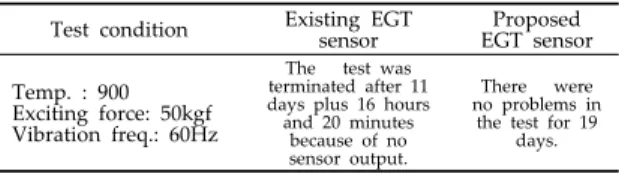
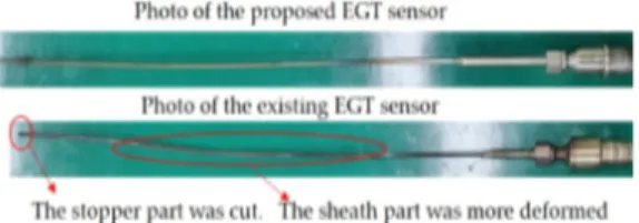
The durability of the proposed EGT sensor and existing EGT sensor was tested using the complex environmental test equipment. The test conditions were determined as high temperature, 900°C, exciting force of vibration, 50kgf, and vibration frequency of 60Hz. The test of the existing EGT sensor was terminated after 11 days plus 16 hours and 20 minutes because of no sensor output, and the proposed EGT sensor was tested for 19 days, but there were no problems. The reason for the defect of the conventional EGT sensor was that the lower part of the stopper welded to the sheath was broken. In addition, the deformation of the sheath of the existing EGT sensor was more severe than that of the proposed EGT sensor. Because the conditions of the test were applied as a short-term period with high temperature and vibration condition, no problems of carbonation at the connector was encountered. The test results are shown in Table 10 and Fig. 17.
Table 10. Comparison of the test results in the complex
environment test equipment
Fig. 17 Test results in the complex environment test equipment
Ⅵ. Conclusion
In this study, the problems of the carbonization of the connector damaged by the heat generated from the EGT sensor, which is installed at the exhaust part of the gas turbine power plant, and the breakage caused by vibration was analyzed.
Also, the life span of the sensor was analyzed.
For improving these problems, the female connector of the EGT sensor cable used a ceramic-glass to metal seal connector to solve the carbonization problem on the connector. In contrast the male connector of the EGT sensor used a glass to metal seal connector in which the carbonization issue was improved by replacing the silicon rubber to carbon.
Also, a ceramic filling material was used to the welding area of the connector of the EGT sensor and the thermocouple to prevent damages caused by vibration. International standards do not suggest measuring the response time under high-temperature conditions of about 700 ℃.
In this paper, a method to measure the response time under high temperature conditions is proposed.
The response time measured by the proposed method is about 0.7 seconds. For the durability test of the proposed EGT sensor, a complex environment test equipment was designed and manufactured to simulate a gas turbine exhaust part that can be used to the tests of heat and vibration at the same time.
In the complex environment tests results, the existing EGT sensor showed a problem of producing
smoke after one hour of the test, and the proposed EGT sensor presented no problem for 168 hours.
In this paper, useful information to solve the problems of the existing EGT sensor and sensor cable and a new method of measuring the response time under high-temperature conditions are proposed.
It is expected that the operation efficiency of the steam power plants can be greatly improved in the future.
In the future research, we plan to install the proposed EGT sensor in the gas turbine of the power plant to test the durability, and we will conduct studies with the durability of the sensors used in the gas turbine.
References
[1] H. Kim, W. Ju and S. Kang, “ A Fire Prevention system of the nacelle of wind turbine generator system based on broadband powerline communication,” J. of The Korea Institute of
Electronic Communication Sciences, vol. 13, no. 6,2018, pp. 1229-1234.
[2] J. Choi and D. Lee, “Android-based Implementation of Remote Monitoring System for Industrial Gas Turbines,” J. of The Korea
Institute of Electronic Communication Sciences, vol.13, no. 2, 2018, pp. 369-376.
[3] S. Lee, J. Lee and G. W. Kim,“ Forecasting the medium term demand of LNG for power generation under the energy transition policy in south korea,” J.l of Climate Chang Research, vol. 10, no. 1, 2019, pp.47-54.
[4] A. Moll, A. Behbahani, G. Fralick, J. Wrbanek and G. Hunter,“A review of exhaust gas temperature sensing techniques for modern turbine engine controls,”
In 50th AIAA/ASME/SAE/ASEE Joint Propulsion Conference, Cleveland, OH, Jul. 2014, p. 3977[5] K. S. Gam,“Characteristics variation of
thermal time constant of thermocouples by
the structure changes’“ J. of Sensor Science and Technology, vol. 18, no. 2, 2009, pp.
103-109.
[6] ASTM E230,
Standard specification for Temperature-Electromotive Force(emf) Tables for Standardized Thermocouples, 2012.[7] IEC 60584-2. Thermocouples, Part 2:Tolerances, 1989.
[8] KS C1602. Thermocouples 2004.
[9] NIST. Available online:
https://srdata.nist.gov/its90/download/type_k .tab accessed on 24 Jan. 2020.
[10] B. Bonnie, Single Supply Temperature Sensing with Thermocouples. AN684, Microchip Technology Inc 1998.
[11] G. D. Abigail, A. M. Alcaráz-Calderón, M. O.
González-Díaz, M. A. Angel, M. Lucquiaud, and J. M. González-Santaló, “M. Effect of the ambient conditions on gas turbine combined cycle power plants with post-combustion CO
2capture,“ Energy, vol. 134, 2017, pp. 221-233.
[12] THERMOCOUPLEINFO. Available online htt ps://www.thermocoupleinfo.com/ accessed on 24 Jan. 2020.
[13] Pyeongtaek energy service power plant. Avail able online https://www.pyeongtaekes.co.kr/
accessed on 24 Jan. 2020.
[14] Sungjin C&T. Available online https://www.sj cnt.co.kr/ accessed on 24 Jan. 2020.
[15] i-Sensor Korea. Available online https://ww w.i-sensor.co.kr/ accessed on 24 Jan. 2020.
[16] Omega. Available online https://www.omega.
com.co.kr/ accessed on 24 Jan. 2020.
[17] CNvision. Available online http://www.cnvisi on.co.kr/ accessed on 24 Jan. 2020.
[18] Eulji corporation. Available online http://ww w.zaze.co.kr/ accessed on 24 Jan. 2020.
저자 소개
이영준(Young-Jun Lee)
2017년 인하대학교 대학원 전기공 학과 졸업(공학석사)
2020년 인하대학교 대학원 전기컴퓨터공학과 졸업(공 학박사)
2007년 ∼현재 성진테크윈 이사
※ 관심분야 : 센서 공학, 서지방호시스템, 임베디드 시스템
정해영(Hai-Young Jung)