Microstrip dual mode band pass filter using doubly fed line
Jeong-pyo Kim
*, Min-soo Lee
**이중 급전 구조를 갖는 마이크로스트립 이중 모드 대역통과 필터
김정표
*, 이민수
**Abstract In this paper, a microstrip dual mode band pass filter with doubly fed line is proposed. The proposed filter consists of a corner truncated patch with right crossed slots and doubly fed lines. In general, the resonator with the right crossed slots simultaneously has size reduction and spurious response suppression. In order to improve the rejection performance in out of its higher stop band, the dual mode resonator is excited by using doubly fed line. Details of the filter characteristics are described, and both simulated and measured results of the designed filter are presented.
요 약 본 논문은 이중 급전을 갖는 마이크로스트립 이중 모드 대역 통과 필터를 제안한다. 제안된 필터는 이중 모드 구현을 위해 모서리 부분을 제거되고, 직교 슬롯을 포함하는 정사각형 패치와 이중 급전 구조로 구성된다. 직교 슬롯 은 공진기의 소형화 및 불요신호를 억압하기 위해 사용되고, 상측 차단 대역에서의 차단 특성을 개선하기 위해 이중 급전 구조를 사용하였다. 보다 자세한 필터 설계 방법 및 특성 결과를 본문에 기술하였다.
Key Words : Dual Mode, Band Pass Filter, Doubly Fed, Conner Truncated Patch, Right Crossed Slots
**Corresponding Author : Dept. Electrical, Electronic and Communication Engineering, Daejin University
Received april 2, 2015 Revised april 7, 2015 Accepted april 10, 2015
1. Introduction
Dual mode resonators have been widely used to realize many RF/microwave filters. A main feature and advantage of resonator lies in the fact that each of dual mode resonators can used as a doubly tuned resonator circuits, and therefore, the number of resonators required for a n-degree filter is reduced by half, resulting in a compact filter configuration[1].
Various microstrip dual mode filters based on the circular ring [2], square loop [3], meander loop resonators [4], circular disk [5], and square patch [6] have been reported. To simultaneously achieve size reduction and
spurious response suppression, the dual mode band pass filter using a square patch with the right crossed slots [7-8] and a coupling and routing scheme [9]. Most of these filters are fed by gap coupling structure because of better spurious response suppression. On the other hand, the directly feed line is used in order to reduce the insertion loss caused by the gap coupling structure [7]. However, the directly feed structure has worse spurious response performance than the gap coupling feed structure.
In this paper, we propose a microstrip dual mode band pass filter using doubly fed line.
The feed line is directly connected to the
designed resonator in order to reduce the insertion loss and has doubly fed line structure in order to achieve better out of band performance.
2. Microstrip Dual Mode Filter Design
S
W
LS
Wf
Lf
Ws
S
W
LS
Ws
(a) (b)
Fig. 1. Dual mode filter structure using (a) a singly fed line and (b) a doubly fed line
Fig. 1 shows two dual mode filter structures excited by using a singly fed line and a doubly fed line. In Fig. 1(b), the characteristic impedance of the branch line and the main line are 100 Ω and 50 Ω, respectively. The square patch resonator has the right crossed slots for size reduction and corner truncated structure to achieve dual mode property [7]. In this work, the dimensions of the resonator are following:
W = 28 mm, S = 9.3 mm, Ls = 20 mm, Ws = 0.5 mm, Lf = 5 mm. These dimensions are fixed and the filters are designed by using AWR AXIEM.
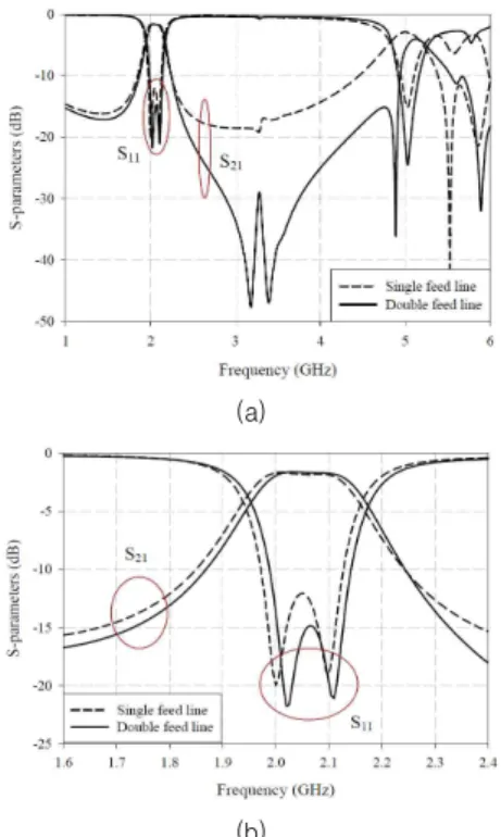
Fig. 2 shows the S-parameters of two filters when Wf = 20 mm. The S11 are less than - 10 dB from 1.972 GHz to 2.128 GHz for the singly fed filter and from 1.987 GHz to 2.142 GHz for the doubly fed filter. The S21 of two filters are higher than - 2.5 dB.
In higher out of band, the insertion loss characteristic of the doubly fed filter is improved more than 10 dB.
Fig. 3 shows S21 by adjusting the distance between two branch lines fed points, Wf. The null point in higher out of band can be controlled by Wf without exchanging the dimensions of the dual mode resonator. Then, the S21 in pass band and the second resonant frequency have no the effect on Wf. When Wf is decreased to 16 mm, the S21 at the second passband is decreased by - 10 dB.
The cut off characteristics in the fundamental pass band is improved by increasing Wf.
(a)
(b)
Fig. 2. S-parameters of two type filters at (a) whole frequency range and (b) near pass band
Fig. 3. Insertion losses by the distance between two
branch lines fed points
Current distribution at center frequency (2.05 GHz) and null point frequency (3.3 GHz) in higher out of band are shown in Fig. 4.
When Wf = 20 mm, the branch fed line plays the good insertion loss property in the out of band.
(a) (b)
Fig. 4. Current distribution at (a) 2.05 GHz and (b) 3.3 GHz
3. Experimental Results
Fig. 5. The fabricated microstrip dual mode band pass filter
Fig. 5 shows the photograph of the fabricated microstrip dual mode band pass filter. The designed filter is constructed on FR-4 substrate with the dielectric constant of 4.4 and the thickness of 0.8 mm. The
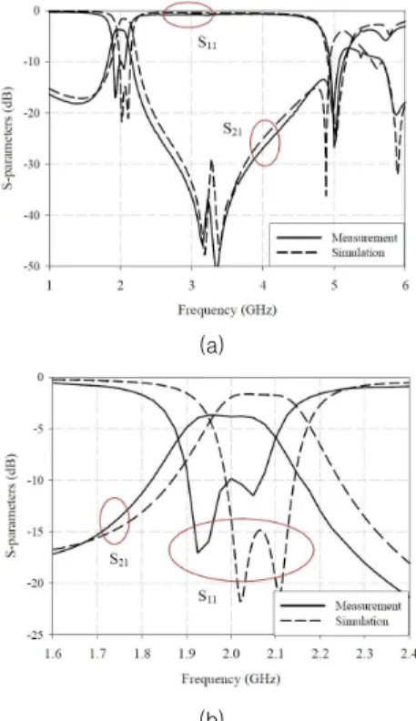
S-parameters of measured and simulated results are shown in Fig. 6. The measured S11 are less than - 10 dB from 1.91 GHz to 2.07 GHz. The measured S21 is higher than -3.6 dB in the pass band and is less than - 30 dB from 2.79 GHz to 3.83 GHz. It confirms that the insertion loss characteristics of the doubly fed filter is improved more than that of the singly fed filter in higher out of band.
Although the measured insertion loss is higher than the simulation results in the pass band, the insertion loss property in higher out of band is very similar to the simulation result.
(a)
(b)
Fig. 6. S-parameters of the proposed filter at (a) whole frequency range and (b) near pass band
4. Conclusion
In this paper, we proposed a microstrip
dual mode band pass filter using doubly fed line. The proposed filter consists of a corner truncated patch with right crossed slots and doubly fed lines. The designed filter has S11 less than - 10 dB from 1.91 GHz to 2.07 GHz and S21 higher than - 3.6 dB in the pass band. In addition, S21 is less than - 30 dB from 2.79 GHz to 3.83 GHz. In higher out of band, the insertion loss characteristic of the doubly fed filter is improved more that of the single fed filter. Because the null point of the insertion loss in higher out of band can be controlled by adjusting the distance between two branch lines fed points, Wf, without exchanging the dimensions of the dual mode resonator, the required insertion loss property can be easily achieved.
REFERENCES
[1] J. S. Hong and M. J. Lancaster, Microstrip Filters for RF/Microwave Applications, John Wiley & Sons, Inc., 2001.
[2] I. Wolff, "Microstrip bandpass filter using degeneration modes of a microstrip ring resonator," Electronics Letters, vol.8, no.12, pp. 302-303, June 1972.
[3] S. Fu, B. Wu, J. Chen, S. Sun, and C.
Liang, "Novel second-order dual-mode dual-band filter using capacitance loaded square loop resonator," IEEE Transactions on Microwave Theory and Techniques, vol.60, no.3, pp. 477-483, Mar. 2012.
[4] J. S. Hong and M. J. Lancaster,
"Microstrip bandpass filter using degenerate mode of a novel meander loop resonator," IEEE Microwave Guided Wave Letters, vol.5, no.11, pp. 371-372, Nov.
1995.
[5] B. T. Tan, S. T. Chew, M. S. Leong, and B. L. Ooi, "A modified microstrip circular patch resonator filter," IEEE Microwave and Wireless Components Letters, vol.12, no.7, pp. 252-254, July 2002.
[6] L. H. Hsieh and K. Chang, "Compact size and low insertion loss Chebyshev-function bandpass filters using dual-mode patch resonator," Eletronics Letters, vol.37, no.17, pp. 1070-1071, Aug. 2001.
[7] W. H. Tu and K. Chang, "Miniaturized dual-mode bandpass filter with harmonic control," IEEE Microwave and Wireless Components Letters, vol.15, no.12, pp.
838-840, Dec. 2005.
[8] S. W. Fok, P. Cheong, K. W. Tam, and R.
P. Martins, "A novel microstrip square-loop dual-mode bandpass filter with simultaneous size reduction and spurious response suppression," IEEE Transactions on Microwave Theory and Techniques, vol.54, no.5, pp. 2033-2041, May 2006.
[9] J. Wang, J. L. Li, J. Ni, S. Zhao, W. Wu, and D. Fang, "Design of miniaturized microstrip dula-mode filter with source-load coupling," IEEE Microwave and Wireless Components Letters, vol.20, no.6, pp. 319-321, June 2010.
[10] NI AWR Design Environment ver.11.
Author Biography
Jeong-pyo Kim [Regular member]
•Feb. 2000 : Jeju National Univ., Dept. of Comm. Eng.,
•Feb. 2002 : Hanyang Univ., Dep. of Ele. and Com. Eng., MS.
•Feb. 2004 ∼ Jun. 2007 : EMW Co., LtD., Engineer
•Aug. 2007 : Hanyang Univ., Dep. of Ele. and Com. Eng., Ph.D.
•Sep. 2007 ∼ Feb. 2010 : Hanyang Univ., Post-DOC.
•Mar. 2010 ∼ Jul. 2011 : EMW Co., LtD., Engineer
•Aug. 2011 ∼ current : RFIS, President
<Research Interests> Antennas, Microwave Components, Metamaterials Min-soo Lee [Regular member]
•Feb. 1984 : Hanyang Univ., Dept. of Electronic and Telecomm. Eng., BS
•Feb. 1987 : Hanyang Univ., Dept. of Electronic and Telecomm. Eng., MS
•Feb. 1994 : Hanyang Univ., Dept. of Electronic and Telecomm. Eng., PhD
•Mar. 1995 ∼ current : Daejin Univ., Dept. of Electrical, Electronic and Communication Eng., Professor
<Research Interests> Antennas, Microwave Components