Vol. 21, No. 2, pp. 64-69, April 2017
중간기 열원수 온도에 따른 만액식 해수냉각시스템의 성능 특성 Performance Characteristics of Flooded Type Evaporator
for Seawater Cooling System with Heat Source Temperature of Mid-year
윤정인*․손창효*․이정목**․강인호***†
Jung-In Yoon*, Chang-Hyo Son*, Jeong-Mok Lee** and In-Ho Kang***†
(Received 18 January 2017, Revision received 09 March 2017, Accepted 09 March 2017)
Abstract: The purpose of this study is to investigate the performance characteristics of seawater cooling system for a fishing vessel. The circulation amount of refrigerant, condensation capacity, evaporation capacity, compression work and coefficient of performance(COP) were analyzed as the heat source temperature changed. The experimental setup consisted of an open-type compressor, a shell&tube type condenser, an evaporator and an expansion valve. The heat source was controlled by a constant temperature chamber. The main results of this study are summarized as follows. The condensation capacity increased with increasing heat source temperature, and it was confirmed that the effect of circulating amount of refrigerant was dominant. The amount of heat for vaporization was almost constant even though the temperature of the heat source increased. On the other hand, the compression power was increased. This is because the compression ratio increases as the condensation pressure, the enthalpy difference between inlet and outlet, the amount of circulating refrigerant increases. The performance coefficient of this system showed a tendency decreasing with increasing heat source temperature.
Therefore, the basic data of the seawater cooling system for the maintenance of the catch line of the shore fishing boats was acquired through this study, and it is considered that it will be sufficient for the actual design.
Key Words:Heat source temperature of mid-year, Seawater cooling system, Performance characteristics, Flooded type evaporator, Coefficient of Performance
***†강인호(교신저자) : ㈜덕산코트랜 E-mail : [email protected], Tel : 053-380-2464
*윤정인, 손창효 : 부경대학교 냉동공조공학과
**이정목 : ㈜코리아 씰테크
***†In-Ho Kang(corresponding author) : Duksan Cotran Co., Ltd.
E-mail : [email protected], Tel : 053-380-2464
*Jung-In Yoon and Chang-Hyo Son : Department of Refrigeration and Air-Conditioning Engineering, Pukyong National University.
**Jeong-Mok Lee : Korea Seal-Tech Co., Ltd.
― 기 호 설 명 ―
Q : 증발 열량 [kW]
G : 질량 유량 [kg/h]
h : 엔탈피 [kJ/kg]
COP : 성능 계수 [ - ]
W : 압축 일량 [kW]
하첨자
ref : 냉매 e : 증발기
1. 서 론
선망어선 어획물의 운반과 저장을 위해 담수빙 을 사용할 경우, 얼음의 불균일한 크기 및 형태에 의해 어획물이 손상될 수 있으며, 담수빙의 융해 열에 의해 어창 내 온도의 불균일성에 따라 어획 물을 신선도에 영향을 미칠 수 있는 단점이 있다.
그리고 담수빙이 어창 내에서 녹으면서 어창 내 염분농도가 감소하게 되는데, 어류는 체내 삼투압 을 유지하려 하나, 결국 항상성이 무너져 선도가 감소하게 된다.1-3) 이와 같은 담수빙의 문제점을 근거로, 어획물의 부가가치를 높이고, 선도 유지 기간을 늘려 조업이 가능한 시간의 범위를 증가 시키기 위한 연구가 필요하지만 우리나라의 경우 이 분야에 대한 연구가 상당히 미흡한 실정이다.
Han4)은 해수냉각시스템의 활어조 내부 열 유동 및 열 부하 특성, 그리고 어류 생존율에 의한 시 스템을 평가하였다. 그 결과 활어조 내부 온도 및 해수 유량, 그리고 압축기 회전수에 대한 가이드 라인을 제시하였다. Perigreen 등5)은 담수빙 사용 방식과 해수냉각방식을 비교하여 후자를 채택하 는 것이 유리하다고 판단하였다. Park6)은 선박냉 동장치의 설계를 위하여 외기온도, 해수온도, 저 장고 유지온도 그리고 어류의 물성치 등을 나열 하여 부하계산을 상세하게 기술하였다. 냉각기 및 히트펌프를 인버터로 제어하는 종래연구를 살펴 보면, Hwang 등7)은 인버터 압축기를 사용하여 외 기부하의 변화에 따라 회전수를 조절하여 기동토 크에 의한 소비전력을 감소시키고, 결과적으로 가 변속시의 비정상 거동을 연구하여 인버터 사이클 의 체계적인 설계를 정립하고자 하였다. Baek 등8) 은 인버터 압축기를 사용하여 압축기 회전수와 외기의 변화에 따른 용량제어 특성에 관한 연구
를 진행하였으며, 압축기 회전수가 증가함에 따른 냉각기의 특성을 정리하였고, 외기온도가 낮아질 수록 용량제어범위가 감소함을 확인하였다. Son 등9)은 해수냉각시스템에 미치는 열원수 온도의 영향에 관한 실험적 연구를 통해 응축열량과의 상호관련성에 대해 밝히고 있다.
만액식 증발기가 설치된 해수냉각시스템의 성 능에 관한 실험적 연구가 대단히 부족할 뿐만 아 니라, 이에 대한 구체적인 성능 특성 연구가 거의 전무하다. 따라서 본 연구에서는 15 kW급 해수냉 각시스템의 실험 장치를 제작하여 성능 특성에 대한 실험적 연구를 수행하였다. 이때 냉각수 온 도를 변수로 하여, 변수 조작에 따른 해수냉각시 스템의 성능 변화를 확인하였다.
따라서 따라 해수냉각시스템의 기초 데이터를 구축하여 우리나라 중간기의 15 kW급 실증 시험 용 선박 탑재 장치의 최적 설계를 위한 기초설계 자료를 제공하는 것이 본 연구의 목표이다.
2. 실험장치 및 방법
2.1 실험장치
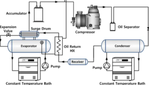
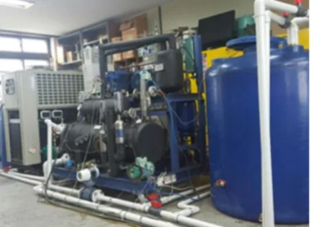
Fig. 1과 2는 해수냉각시스템의 성능분석을 위 한 개략도와 실험장치 사진을 나타낸 것으로, 압 축기는 개방형으로, 모터와 압축기는 벨트로 연결 되어 압축기로 동력이 전달됨에 따라 장치의 운 전이 가능하다. 응축기는 쉘 앤 튜브 식으로 쉘 측에는 냉매가, 튜브 측에는 냉각수가 흐른다. 팽 창밸브는 증발기 출구온도를 측정하여 냉매 순환 량을 제어할 수 있도록 하였다.
Fig. 1 P&ID of the seawater cooling system
Fig. 2 Photo of experimental apparatus.
증발기는 만액식을 사용하였고, 응축기와 마찬 가지로 쉘 측에는 냉매가, 튜브 측에는 냉수가 흐 른다. 증발기의 액면을 조절하기 위하여 두 개의 플로트 스위치가 설치되었다.
증발기는 만액식을 사용하였고, 응축기와 마찬 가지로 쉘 측에는 냉매가, 튜브 측에는 냉수가 흐 른다. 증발기의 액면을 조절하기 위하여 두 개의 플로트 스위치가 설치되었다.
액면이 하한선까지 낮아지는 경우 솔레노이드 밸브가 개방되어 냉매가 순환할 수 있게 하며, 액 면이 상한선까지 높아지는 경우 솔레노이드 밸브 가 차단되어 증발기로의 냉매 순환을 차단시키고 액 압축을 사전에 방지하는 역할을 한다.
2.2 작동유체 선정과 열원수 온도
선망어선용 해수 냉각시스템의 작동유체는 성 능계수, 안전등급, 오존파괴지수(Ozone Depletion Potential, ODP) 등을 고려하여 선정해야 한다.
R134a는 비가연성, 무독성, 우수한 안전등급, 낮은 ODP의 장점으로, 본 연구의 작동유체로 R134a를 선정하였다.
국내의 선망어선들은 제주해협에서 대부분 조 업하고 있다. 최근 3년간의 제주해협 표층수온(열 원수온)을 근거로, 중간기인 6∼8월 사이의 평균 수온이 19∼25℃ 정도 된다. 따라서 본 연구에서 는 중간기 열원수 온도를 19∼25℃로 설정하였다.
2.3 실험 및 시뮬레이션 조건
실험조건은 Table 1에 나타낸 것처럼, 인버터의 주파수를 60 ㎐로 설정하여 회전수를 일정하게
유지한 후, 증발기에서 냉수 입구 온도를 5℃, 냉 수 출구 온도를 3℃로 유지시켰다. 냉동능력이 약 15 kW일 때 냉각수의 온도를 19℃부터 25℃까지 상승시키며 시스템 특성을 분석하였다.
Parameter Unit Value
Refrigerant - R134a
Chilled water temperature at
evaporator inlet ℃ 5 Chilled water temperature at
evaporator outlet ℃ 3 Heat source temperature at
condenser inlet ℃ 19, 21, 23, 25 Inverter frequency ㎐ 60 Table 1 Experimental conditions
해수냉각시스템의 성능 특성을 이론적으로 분 석하기 위해서 상용프로그램인 HYSYS10)를 사용 하였으며, 이때 분석 조건은 Table 1의 실험조건 과 동일하다.
2.4 데이터 해석
해수 냉각시스템의 응축열량, 증발열량, 압축동 력, COP 등을 통해 성능 특성을 확인할 수 있었 으며, 이들 식은 다음과 같다. 우선, 응축열량은 응축기 입출구의 엔탈피 차로 구할 수 있다.
∙ (1)
식 (2)의 증발열량은 식 (1)과 마찬가지로, 증발 기 입출구의 엔탈피 차로 계산할 수 있다.
∙ (2)
본 실험장치의 성능계수(COP)는 증발열량과 압 축일량과의 비율로 나타낼 수 있다.
(3)
여기서, 압축일량(W)은 압축기를 가동할 때 전 력을 파워메터로 직접 측정하여 사용하였다.
3. 해석결과 및 고찰
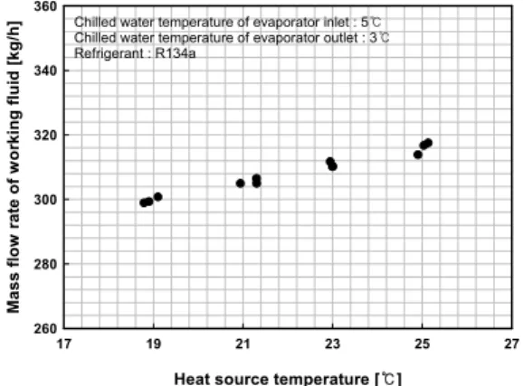
Fig. 3은 열원수 온도 변화에 따른 냉매의 순환 량을 나타낸 것으로, 열원수 온도가 높아질수록 냉매 순환량이 증가함을 알 수 있다. 이는 동일한 과냉도 또는 포화상태에서 냉동효과가 감소하기 때문에, 각 분석조건에서의 냉동능력을 일정한 수 준으로 유지시키기 위해서 냉매 순환량이 증가되 어야 함을 확인할 수 있다.
Fig. 4는 열원수 온도 변화에 따른 응축열량의 변화를 나타낸 결과로서, 실험 데이터의 경우 열 원수 온도가 증가할수록 응축열량이 증가하였다.
이는 냉매 순환량이 증가하기 때문이다.
Heat source temperature [ ]℃
17 19 21 23 25 27
Mass flow rate of working fluid [kg/h]
260 280 300 320 340 360
Chilled water temperature of evaporator inlet : 5℃
Chilled water temperature of evaporator outlet : 3℃
Refrigerant : R134a
Fig. 3 Flow rate of working fluid with respect to heat source temperature
Heat source temperature [ ]℃
17 19 21 23 25 27
Condensation capacity [kW]
10 15 20 25 30
Chilled water temperature of evaporator inlet : 5℃
Chilled water temperature of evaporator outlet : 3℃
Refrigerant : R134a
● : Experimental data : Hysys data
Fig. 4 Condensation capacity with respect to heat source temperature
추가적으로 응축열량에 영향을 미칠 것으로 판 단되었던 습증기영역에서의 엔탈피 감소분과 과 열영역에서의 엔탈피 증가분의 차는 냉각수 온도 의 증가에 따라 오히려 감소하는 경향을 보였다.
따라서 열원수 온도에 따른 응축열량의 변화에 영향을 미치는 요소는 엔탈피 변화율 보다 냉매 순환량의 변화율이 지배적임을 확인할 수 있다.
Table 1의 분석조건에 따라 분석프로그램을 사 용하여 응축열량을 계산하였다. 이때, 응축열량은 실험 데이터와 동일한 경향을 보였으며, 열원수 19℃의 경우를 제외하고는 실험 데이터가 높았다.
이는 냉각수의 유량이 필요 유량보다 많기 때문 인 것으로 판단된다.
Fig. 5는 열원수 온도의 증가에 따른 증발열량 과 압축동력의 변화를 나타낸 것이다. 우선 증발 열량의 실험 데이터 경우, 열원수 온도가 증가할 수록 소폭 증가하는 경향을 보였다. 이는 열원수 온도 증가와 함께 냉매 순환량이 증가되기 때문 이다. 상용프로그램을 사용하여 계산된 증발열량 은 실험 데이터와 거의 일치하였다.
Heat source temperature [ ]℃
17 19 21 23 25 27
Evaporation capacity [kW]
6 8 10 12 14 16 18
3 4 5 6 7
Compressor work [kW]
Chilled water temperature of evaporator inlet : 5℃
Chilled water temperature of evaporator outlet : 3℃
Refrigerant : R134a
Evaporator capacity
Compressor work
▲ ● : Experimental data : Hysys data
Fig. 5 Evaporator capacity and compressor work respect to heat source temperature
압축동력에 대한 실험 데이터의 경우, 열원수 온도의 증가에 따라 냉매 순환량이 증가하였다.
이는 압축비가 높아짐에 따라 압축기 입출구의 냉매 엔탈피 차가 커지기 때문임을 알 수 있다.
상용프로그램을 사용하여 구한 압축동력은 실험 데이터와 거의 일치하는 경향을 보였다.
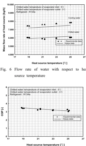
Fig. 6은 열원수 온도 변화에 따른 응축기 및 증발기로 흐르는 냉각수 및 냉수의 유량을 각각 나타낸 것이다. 우선 냉각수의 경우, 상용프로그 램을 사용하여 계산한 유량과 비교하여 실험 데 이터의 유량이 많았으며, 이는 응축기의 쉘 측을 흐르는 냉매 액이 열교환기 설계조건보다 과냉도 가 높은 상태로 토출되었음을 예상할 수 있다. 적 절한 과냉도가 유지되기 위한 냉각수 유량의 최 적 제어가 필요함을 알 수 있다. 또한, 실험 데이 터와 이론 데이터 모두 증가하는 경향을 보였다.
Heat source temperature [ ]℃
17 19 21 23 25 27
Mass flow rate of heat sourec [kg/h]
4.000 5.000 6.000 7.000 8.000 9.000 10.000
Chilled water temperature of evaporator inlet : 5℃
Chilled water temperature of evaporator outlet : 3℃
Refrigerant : R134a
Cooling water
Chilled water
▲ ● : Experimental data : Hysys data
Fig. 6 Flow rate of water with respect to heat source temperature
Heat source temperature [ ]℃
17 19 21 23 25 27
COP [-]
0 1 2 3 4 5 6
Chilled water temperature of evaporator inlet : 5℃
Chilled water temperature of evaporator outlet : 3℃
Refrigerant : R134a
● : Experimental data : Hysys data
Fig. 7 COP with respect to heat source temperture
4. 결 론
지금까지 열원수 온도 변화에 따른 해수냉각시 스템의 성능 특성에 대해서 살펴보았다. 그 결과
를 요약하면 다음과 같다.
1) 열원수 온도가 증가함에 따라 냉매 순환량은 증가하였다. 또한 증발기 입출구의 엔탈피 차의 감소에 따라 냉동효과가 감소하므로, 일정한 운전 조건에서 일정한 냉동능력을 얻기 위해서 냉매 순환량이 증가함을 확인할 수 있었다.
2) 응축열량이 열원수 온도가 증가함에 따라 증 가하였으며, 냉매 순환량에 의한 영향이 지배적임 을 확인할 수 있었다.
3) 증발열량은 열원수 온도가 증가함에도 거의 일정하였다. 이와 달리, 압축동력은 증가하였다.
이는 응축압력이 증가함에 따라 압축비가 커지고, 입·출구 엔탈피 차가 증가하기 때문이며, 냉매 순 환량의 증가 또한 그 원인임을 확인하였다.
4) 본 시스템의 성능계수는 열원수 온도가 증가 함에 따라 감소하는 경향을 보였다. 따라서 본 연 구를 통한 결과들은 선망어선의 어획물 선도 유 지를 위한 해수냉각시스템의 만액식 증발기 설계 에 충분한 도움이 될 수 있을 것이라 판단된다.
후 기
본 연구는 2016년 해양수산부 재원으로 한국해 양과학기술진흥원의 지원을 받아 수행된 연구임 (선망 어선용 해수 냉각 시스템 도입 연구).
References
1. C. H. Son, I. H. Kang, J. N. Lee, C. L. Kim and J. I. Yoon, 2016, "Characteristics of Refrigeration System for Fishing-ships Applying Flooded Evaporator", Proceedings of 2016 ICETA Spring Meeting, Taipei, Taiwan.
2. J. I. Yoon, K. H. Choe, C. H, Son, I. H. Kang, C. L. Kim and S. H. Seol, 2015, "Performance Comparison of Flooded Seawater Cooling System with respect to Heat Sink Temperature", Journal of the Korean Society for Power System Engineering, Vol. 19, No. 6, pp. 17-24, 2.
3. K. S. Lee, 2014, "The Effects of Salinity
Change Caused by Freshwater Discharge in Estuary on Coastal Marine Life", The Korean Society of Marine Environment & Safety, pp.
351-352.
4. I. G. Han, 2002, "Study on Characteristic Performance and Evaluation of Sea Water Chilling System", Doctoral Dissertation, Pukyong National University.
5. P. A. Perigreen, S. A. Pillal, P. K. Surendran and T. K. Govindan, 1975, "Studies on Preservation of Fish in Refrigerated Sea-water", Central Institute of Fisheries Technology, Vol.
12, No. 2, pp. 105-111.
6. K. W. Park, 2005, "Design Basis of Marine Refrigeration System", Journal of the Korean Society of Marine Engineering, Vol. 29, No. 8, pp. 14-19.
7. Y. J. Hwang and H. Y. Kim, 1998, "A Study on
the Transient Characteristics during Speed Up of Inverter Heat Pump", Korean Journal of Air-Conditioning and Refrigeration Engineering, Vol. 10, No. 4, pp. 495-507.
8. S. M. Baek, C. G. Moon, E. P. Kim, S. K.
Heong and J. I. Yoon, 2011, "The Characteristic Study of Capacity Control of an Industrial Cooler Using an Invertor Compressor with Varing the Ambient Temperatures", Journal of the Korean Society of Marine Engineering, Vol, 35, No. 2, pp. 238-243.
9. C. H. Son, J. I. Yoon, S. H. Jung, C. L. Kim, S. H. Seol and I. H. Kang, 2016, "Experimental Study on Seawater Cooling System of Effects on Heat Source Temperature", Proceeding of the 40th KOSME Spring Conference, p.83
10. Aspen HYSYS, Version 8.6, Aspen Technology Inc, 2014.