한국복합신소재구조학회 논문집 제5권, 제1호, 2014년 3월
J. Korean Soc. Adv. Comp. Struc. Vol. 5, No. 1, pp. 28-36, March 2014 DOI http://dx.doi.org/10.11004/kosacs.2014.5.1.028
ISSN 2093-5145(Print) ISSN 2288-0232(Online)
강재보와 합성기둥에 사용된 새로운 반강접 접합부의 설계
손홍민1 · Roberto T. Leon2 · 허종완3
인천대학교 건설환경공학과 박사과정1
버지나아택 토목 및 환경공학과 교수2,
인천대학교 건설환경공학과 교수3
Design of Innovative SMA PR Connections Between Steel Beams and Composite Columns
Hong Min Son · Roberto T. Leon · Jong Wan Hu3
Ph.D, Department of Civil and Environmental Engineering, Incheon National University, Incheon, Korea
Professor, Virginia Polytechnic Institute and State University, Virginia, USA
3Professor, Department of Civil and Environmental Engineering, Incheon National University, Incheon, Korea
Abstract: This study describes the development of innovative connections between steel beams and concrete-filled tube columns that utilize a combination of low-carbon steel and super-elastic shape memory alloy components. The intent is to combine the recentering behavior provided by the shape memory alloys to reduce building damage and residual drift after a major earthquake with the excellent energy dissipation of the low-carbon steel. The analysis and design of structures requires that simple yet accurate models for the connection behavior be developed. The development of a simplified 2D spring connection model for cyclic loads from advanced 3D FE monotonic studies is described. The implementation of those models into non-linear frame analyses indicates hat the recentering systems will provide substantial benefits for smaller earthquakes and superior performance to all-welded moment frames for large earthquakes.
Key Words: steel beams, utilize a combination of low-carbon steel, recentering systems
주요어: 강철빔, 초탄성 형상기억 합금, 저탄소 빔 Corresponding author: Jong Wan Hu
Department of Civil Engineering, #12-1 Songdo-dong, Yeonsu-gu, Incheon, 206-840, KOREA Tel: +82-2-3141-0774, Fax: +82-2-3141-0774, E-mail: [email protected]
투고일: 2014년 2월 24일 / 수정일: 2014년 3월 7일 / 게재확정일: 2014년 3월 14일
1. INTRODUCTION
In recent years, concrete filled steel tube (CFT) columns have become widely accepted and used in multistory buildings as well as bridges. These elements provide the synergetic advantages of ductility and toughness associated with steel structures and high compressive strength associated with confined concrete components. The advantages of CFT columns over other so-called mixed or hybrid systems (fully encased or partially encased systems) include the fact that the concrete prevents local buckling of the steel tube wall
and the confinement action of the steel tube extends the usable strain of the concrete. In addition, CFT columns have improved fire resistance and significant cost reductions in comparison with traditional steel construction. Composite CFT columns are especially efficient as the vertical elements in moment resisting frames located in high seismic areas because they have a high strength to weight ratio, provide excellent monotonic and dynamic resistance under biaxial bending plus axial force, and improve damping behavior (Tsai et al. 2004).
Recently, work at Georgia Tech on shape memory alloys (SMA) has explored the applications of these
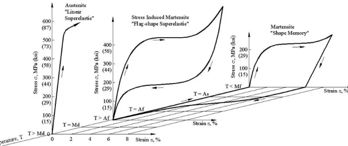
materials to the design of connections in steel structures subjected to large cyclic loads. SMA materials can undergo large deformations with little permanent residual strain through either the shape memory effect or the super-elastic effect. The deformations can be recovered with changes in either temperature or stress as shown in Figure 1. In this research, the recentering properties of flag-shaped super-elastic SMA will be combined with the large energy dissipation of conventional low-carbon steels to develop a new type of connection for use in low-rise structures with CFT columns.
The proposed new connections are shown in Figure 2. These connections use three types of conventional PR connections (end plates, T-stubs and clip angles) but incorporate SMA and steel bars as the primary yielding elements. It is hypothesized that such combinations of CFT columns and SMA connections will achieve excellent ductility, upgraded energy dissipation and recentering capabilities.
Fig. 2 Proposed New Connections to Rectangular CFT Columns
This paper is divided into two parts: (1) the development of a simplified 2D joint model suitable for numerical analyses using an open-source program, and (2) studies of the non-linear behavior of prototype 4 and 6-story composite moment frames using the OPENSEES program (Mazzoni 2006).
2. SMA PR-CFT CONNECTION DESIGN AND JOINT MODEL
All connections in this study were designed as full strength (FS), meaning that they can transfer the full plastic beam moment calculated according to the LRFD Standard (AISC 2001). The connection design, however, did not aim to achieve full restraint (FR or full end rigidity); it intended to utilize PR behavior to obtain ductile connection behavior. Joint components such as tension bars, shear/web bolts, welded stiffeners, and end-plates were designed with the intent of preventing or reducing loss of stiffness and strength due to brittle failure modes. Therefore, the dominant modes of the steel or SMA components will be ductile ones, ranging from very ductile such as tensile yielding of steel to moderately ductile such as minor local bucking. The connection selected for discussion in this paper is an end plate one (Figure 3). The connections were fabricated with an assembly of various steel members cut from standard shapes available in the current design specification (AISC 2001). A572 Grade 50 steel was Fig. 1 Characteristics of Shape Memory Alloys (Penar 2005)
Hong Min Son · Roberto T. Leon · Jong Wan Hu
12.5’ CFT Column End-Plate
14.5’ W24X103 Beam
Loading Point
12.5’ CFT Column End-Plate
14.5’ W24X103 Beam
Loading Point
HSS 16X16X0.5
SMA Bar = 1 Steel Bars = 2 W24X103
End Plate 38.5 x 15 x 1
1 1 2 2 2 2 1 1
All bars 20 in.long x 1 in.
threaded 2 in. both ends 1 in. stiffener
Through tension bars on
a 6x6 spacing
(a) Subasemblage for 3D FE studies (b) Connection details Fig. 3 End Plate SMA PR-CFT Connection
used for all members and joint components. A490 high strength bolt material was used for steel bars, with matching materials for washers and nuts. Super-elastic (SE) Nitinol bars, with the characteristics shown in Figure 1, were located where the largest deformations were likely to occur and where their recentering effect would be maximized. Extended stiffener plates welded between the connected beam flange and the end-plate were required to maintain stiffness.
The ABAQUS Version 6.6-1 (ABAQUS, 2006) finite element code was used to analyze the proposed PR-CFT connections. These numerical 3D, symmetric models consisted of refined 3D solid elements incorporating the full nonlinear material/ geometric properties, contact elements, surface interaction with friction, constraint conditions using equation points, concrete crack conditions and elastic foundation springs.
These advanced modeling methods were intended to provide a detailed and accurate understanding of the overall behavior of the connections, including the stress distributions on the contact surfaces in spite of the high computational cost typically associated with this type of approach. The results of a typical analysis are shown in Fig. 4. These results were used to verify that the end plate was thick enough to behave as a rigid element, that prying forces could be accurately measured, and that the transition points in the load
deformation curves for individual components could be modeled by simple springs.
After careful calibration of the 3D models to test data from SAC tests (FEMA 2000) and investigation of local behavior such as concrete crushing under the heads of the tension bars, the data from these monotonic studies was used to develop simplified 2D joint elements for use in OPENSEES. This program allows the implementation of user-defined elements such as the one proposed here (Figure 5). This element includes four equivalent spring elements (S1) to reproduce the behavior of the tension bars, four internal spring elements (S2) to reproduce the axial deformation of the CFT column, four internal shear springs (S3) to reproduce the shear deformation of the CFT column and the beam, and one shear panel element (C) which is intended to reproduce the failure of the panel zone under severe loading. End-plates are modeled as rigid-plates in the joint element, and the beam and CFT columns are modeled as a nonlinear beam-column element with 2D fiber sections attached to the joint element.
Fig. 4 Results of 3D FE Analysis Showing Deflected Shapes and Behavior of both SMA and Steel Tension Bars
(a) Elements near the connection (b) Connection Model
Fig. 5 Connection Model and Joint Element
Hong Min Son · Roberto T. Leon · Jong Wan Hu
(a) Steel Bar Component Model (b) SMA Bar Component Model (c) Bearing Component Model No Tension
Material SMA
Hysteretic UMAT Material
Force-deformation characteristics for these components were modeled by equivalent spring elements (such as S1, Figure 5) installed in the joint element. Each component bar was modeled as individual component, as shown in Figure 5, with the cyclic behavior bounded by the monotonic FE results and material properties. The cyclic behavior does not incorporate large strength and stiffness degradation because the designs were meant to result in connections that exhibited good hysteretic behavior. The 3D FE studies had shown that attempting to model large loss of strength and stiffness would lead to numerical problems and the need for sophisticated damage accumulation models in order to accurately predict the connection behavior. That type of model would not have been suitable for the 2D simplifications desired here.
Because the deformation of the panel zone often contributes significantly to the drift of moment frames, care was taken to include in the model a reasonable composite panel zone component. The required information for this model, such as initial stiffness, yield shear, and ultimate shear strength were generated by using the equations proposed by Wu (Wu et al.
2007). The theoretical equations for this behavioral property consider both strengthened shear stiffness due to composite action and stiffness loss due to bar holes.
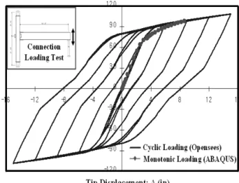
The shear strength of the composite panel zone is taken the superposition of shear strengths between a steel tube and inside concrete core and was modeled using the hardening material model in OPENSEES Initially, and for calibration purposes, the 2D joint models were subjected to loads applied to the tip of the beam corresponding to the position of a loading actuator (Fig. 3). A comparison between the monotonic results from the 3D FE model and the cyclic results of the joint element model is given in Figure 6. The data corresponds to the case of an end plate with 4 SMA and 4 steel bars top and bottom. The curves show
good agreement in terms of initial stiffness, ultimate strength, and envelopes for the force-displacement behavior curves. In general, the 3D monotonic curves show less available strain because of numerical problems associated with the concrete model. For the cyclic behavior, the recentering effect can be observed during unloading due to the super-elastic (SE) SMA materials.
Results for the recentering effect depending on the types of bar materials are given in Figure 7 for the same type connection as shown in Figure 6. The joint element model equipped only with the component model of SE-SMA tension bars (Fig. 7(a)) shows excellent recentering ; however, plastic deformation of the beam causes some growing residual displacements in the moment vs. rotation curve. On the other hand, the behavior of the connection with steel tension bars only (Fig. 7(b)) shows much fatter hysteresis loops.
Thus, steel tension bars can increase the energy capacity and provide improved resistance. The joint equipped with both steel tension bars and SE-SMA tension bars (Fig. 6) takes advantage of both effects;
full recentering behavior requires that the lower shelf of the stress-strain for the flag-shaped superelastic SMA provide enough restoring force to yield the steel bars in compression. Finally, a comparison of connection behavior for two different connection types (a fully welded (FR/FS) connection and one with steel and SMA tension bars) is given in Figure 8. For the static monotonic curves, the initial slope of the welded connection is steeper than that of the smart PR-CFT connection. However, the welded connection evidences smaller hardening after yielding. The welded connection also shows much more permanent deformation during unloading.
Fig. 6 Properties of Typical Equivalent Springs
-120 -90 -60 -30 0 30 60 90 120
-16 -12 -8 -4 0 4 8 12 16
-120 -90 -60 -30 0 30 60 90 120
-20 -15 -10 -5 0 5 10 15 20
Tip Displacement: ∆ (in)
Total Applied Force: T (kip)
Tip Displacement: ∆ (in)
Total Applied Force: T (kip)
SE SMA Bar Case Steel Bar Case
(a) All SMA Bars (b) All Low-Carbon Steel Bars
Fig. 8 Comparison of Connection Behavior for All SMA or All Steel Bars
-150 -100 -50 0 50 100 150
-30 -20 -10 0 10 20 30
Smart PR-CFT Connection Welding (FR) CFT Connection 0
20 40 60 80 100 120
0 5 10 15 20 25
Smart PR-CFT Connection Welding (FR) CFT Connection
Tip Displacement (in)
Total Applied Force: T (kip)
The Static Monotonic Test (OPENSEES)
Tip Displacement (in)
Total Applied Force: T (kip)
The Cyclic Test (OPENSEES)
SMA PR-CFT Connection Welded FR-CFT Connection
SMA PR-CFT
Connection Welded FR-CFT
Connection SMA PR-CFT Conn.
Welded FR-CFT Conn.
(a) Monotonic (b) Cyclic
Fig. 9 Comparison of PR vs. FR Connection Behavior Fig. 7 Comparison of Monotonic and Cyclic Results
3. NUMERICAL MODELS FOR COMPOSITE MOMENT FRAMES
This section describes the building configuration, the numerical modeling attributes, and nonlinear frame analyses conducted for composite moment frames. The design dead and live loads for composite moment frames and the companion steel FR frames designed for comparison, are assumed as 100 psf and 80 psf, respectively. A seismic design category (SDC) of D was assigned to the buildings, based upon the occupancy class and the seismicity of the site (LA and Seattle areas). All composite moment frames are designed in accordance with the ASCE 7-02 and AISC 2005 Seismic Provisions (AISC 2005) for gravity loads and lateral loads, respectively.
Hong Min Son · Roberto T. Leon · Jong Wan Hu
The configurations of 6 story composite building are illustrated in Figure 9 (b) and (c). The total height is 78 ft., with uniform 13 ft. floor heights. This building has 3 bays by 5 bays, with perimeter moment frames in the EW direction and interior moment frame sin the NS direction. Except for moment resisting frames, all beams to column connections are assumed as pinned connections. The panel zones were designed in accordance with AISC 2005 for the steel FR frames and by the Wu et al. (Wu, 2007) procedure for the SMA PR-CFT connections. SMA PR-CFT connections were modeled using the joint element corresponding to the connection details shown in Figure 4.
Both monotonic and cyclic pushover analysis using equivalent lateral loads and nonlinear dynamic analysis under a set of 20 ground motions (10 ground motions for the Los Angeles (LA) area and 10 ground motions for the Seattle (SE) area) were performed.
For the nonlinear pushover analyses, load factors and combinations conform to the ASCE7-02 and LRFD (AISC2001) specification. Load combination 5 (LC 5: 1.2DD + 1.0LL + 1.0E) dominated over other load combinations. The resulting monotonic/cyclic pushover curves plotted as the interstory drift ratio (ISDR) at the roof level vs. the normalized base shear force (VBase/VDesign) are shown in Figure 10. Note that in Figure 8(a), both the FR Fig. 10 Modeling of the Composite Frame Structure for Nonlinear Frame Analyses
-30 -20 -10 0 10 20 30 40
0 4 8 12 16 20
6END-C1 6END-C7
-30 -20 -10 0 10 20 30
0 10 20 30 40 50 60 70
6END-C1 6END-C7
Time (sec)
Displacement (in)
Time (sec)
Displacement (in)
SMA PR-CFT Connection Frame Welded FR-CFT
Connection Frame
Welded FR-CFT Connection Frame SMA PR-CFT
Connection Frame
SAC LA21 Motion SAC LA26 Motion
Fig. 12 Comparison of Nonlinear Dynamic Analyses (SMA PR vs. Welded FR)
0 0.03 0.06 0.09 0.12 0.15
0 1 2 3 4 5
Inter Story Drift Ratio (Δroof/ H) Normalized Base Shear (VBase/VDesign)
Normalized Base Shear vs. ISDR at the Roof
Welded FR-CFT Connection Frame
(Welded Conn.) SMA PR-CFT Connection Frame (End-Plate Conn.) Roof Height (H) = 78’ =936 in
VDesign= ΣEi =234 kips
0.12 0.06 0 0.06 0.12
5 2.5 0 2.5
5 END-Plate Conn.
Welded Conn.
Normalized Base Shear (VBase/VDesign)
Normalized Base Shear vs. ISDR at the Roof
Inter Story Drift Ratio (Δroof/ H) H
Δ
H Δ
ISDR=Δ/H L1
L2
L3
(a) Monotonic Pushover (b) Cyclic Pushover
Fig. 11. Comparisons of Nonlinear Pushover Analyses (SMA PR vs. Welded FR)
and FR connections have similar strength but different stiffnesses. Current design specification do not recognize the lengthening of the period due to PR connections and thus the design base shears for both types of frames was similar. The rapid deterioration of the welded frames is attributable to the relatively low ductility assumed for the WUF-B connections in the FR frames. In addition, the degradation is tied to the larger loss of stiffness in the columns in these frames due to yielding and the consequent larger effect of P-D moments.
The nonlinear dynamic analyses were performed by using two suites of 20 earthquake ground motions with 2% probability of exceedance in 50 years for the western area (LA21to LA30 and SE21 to SE30, Somerville et al., 1997). In addition to dead loads and
live loads, a combination of masses corresponding to 1.0DD+0.2 LL were applied to generate the inertial force due to the acceleration; 2.5 % Rayleigh damping was used in the first mode. Both geometric and material nonlinearities were considered during all nonlinear analyses. Figure 11 shows a typical result of these analyses, which indicate a significant reduction of the maximum drift for PR frames under a large pulse-type earthquake (LA21), but a similar level of residual deformation; the latter is due to the large amount of yielding at the column bases, which the SMA cannot overcome. More distinct differences in dynamic characteristics after first damage are shown for the LA26 ground motion.
Hong Min Son · Roberto T. Leon · Jong Wan Hu
CONCLUSIONS
The smart PR-CFT connections developed in this study are an innovative structural element that takes advantage of the synergistic characteristics of the composite system, flexible PR connections, and use of new materials. The structural advantages and characteristics for these composite moment frame were verified by the nonlinear analyses performed on the numerical frame models with joint elements. The effective evaluations for seismic performance and structural damage were also presented in this study.
ACKNOWLEDGEMENTS
The work was supported partially through NSF Grant CMMI-0619047. The opinions and conclusions expressed here are solely those of the authors.
References
ABAQUS v. 6.6-1, 2006. Hibbit, Karlsson & Sorensen, Inc., Pawtucket,RI.
American Institute of Steel Construction (AISC) (2001), Manual of Steel Construction, Load and Resistance Factor Design (LRFD), 3rd Ed., Chicago,IL.
American Institute of Steel Construction (AISC) (2005), Seismic Provisions for Structural Steel Buildings (ANSI/AISC 341-05), Chicago,IL.
American Society of Civil Engineers (ASCE) (2002), Minimum Design Loads for Buildings and Other Structures, ASCE 7-05
Federal Emergency Management Agency (FEMA) (2000), State of the Art Report, FEMA 355C, SAC Joint Venture, Washington,D.C.
Mazzoni, S., Mckenna, F., and Fenves, G. L., (2006), OPENSEES Command Language Manual, CEE, UniversityofCalifornia,Berkeley.
Penar, B. W., (2005), Recentering Beam-Column Connections using Shape Memory Alloys, Master’s Thesis, The Graduate School, Georgia Institute of Technology.
Somerville, P.G., Smith, N., Punyamurthula, S., and Sun, J., (1997), Development of Ground Motion Time Histories for Phase 2 of the FEMA/SAC Steel Project, SAC Background Document, Report No.
SAC/BD 97/04.
Tsai, K. C., Weng, Y. T., and Ling, M. L., 2004. Pseudo Dynamic Tests of a Full-Scale CFT/BRB Composite Frame, ASCE 2004 Structures Congress, ASCE Wu, L. Y., Chung, L. L., Tsai, S. F., Lu, C. F. and
Huang, G. L., 2007. Seismic Behavior of Bidirectional Bolted Connections for CFT Columns and H-Beams, Engineering Structures, v.29, pp. 395-407