• 검색 결과가 없습니다.

3D BIM Modeling of Temporary Structure for Earthwork using Parametric Technique

N/A
N/A
Protected

Academic year: 2021

Share "3D BIM Modeling of Temporary Structure for Earthwork using Parametric Technique"

Copied!
9
0
0

로드 중.... (전체 텍스트 보기)

전체 글

(1)

와카스 아샤드 타놀리

1)

, 하스나인 라자

2)

, 이승수

3)

, 박상일

4)

, 서종원

5)

Waqas Arshad Tanoli

1)

· Hassnain Raza

2)

· Lee, Seung-Soo

3)

· Park, Sang-Il

4)

· Seo, Jong-won

5) Received February 2, 2018; Received April 16, 2018 / Accepted June 13, 2018

파라메트릭 기술을 이용한 토공용 임시 구조물의 3D BIM 모델링

3D BIM Modeling of Temporary Structure for Earthwork using Parametric Technique

DOI: https://doi.org/10.13161/kibim.2018.8.2.001

ABSTRACT: Nowadays Building Information Modeling (BIM) is a significant source of sharing project information in the construction industry.

This method of sharing the information enhances the project understanding among stakeholders. Modeling of information using BIM is becoming an essential part of many construction projects around the globe. Despite rapid adoption of BIM in construction industry still, some sectors of the industry like earthwork have not yet reaped its full benefits. BIM has brought a paradigm shift through identification and integration of the roles and responsibilities of project participants on a single platform. BIM is a 3D model-based process which provides the insight into the efficient project planning and design. The 3D modeling can also be used significantly for the design of temporary structures in an earthwork project. This paper presents the quantity take-off methodology and parametric modeling technique for creating the temporary structures using 3D BIM process. A case study is conducted to implement the proposed temporary structure family design on a real site project. The study presented is beneficial for the earthwork project stakeholders to extract the relevant information using 3D BIM models in a project. It provides an opportunity to calculate the quantity of material required for a project accurately.

KEYWORDS: Earthwork, 3D BIM, Quantity take-off, Temporary Structure 키 워 드: 토공사, 3D BIM, 물량산출, 임시 구조

1. Introduction

BIM technology has been successfully applied in the AEC (Architecture, Engineering, and Construction) industry (Azhar et al., 2012), it supports parametric design and greatly improves the accuracy of modeling. BIM process is widely adopted in all the sectors of the construction industry. It removes obstacles which hinder in the successful completion of the project, and it has modified the construction process. BIM 3D models have replaced conventional 2D drawings and provided benefits for designer and clients to test multiple design option without

spending construction cost (Azhar et al., 2011). Sharing project information with all stakeholders of the project has become convenient through this process. All the information of project from design to completion is convenient to manage using BIM (Volk et al., 2013). 4D and 5D BIM are used to overcome the challenges of schedule and cost in a project (Smith, 2016; Fan et al., 2009). BIM process gives optimized design by reducing cost overrun of the project. Optimized design analysis can be performed by detail object-based information modeling for all major components required for project completion. BIM effectiveness can also be utilized by parametric technique for

1)

학생회원, 한양대학교 건설환경공학과 박사과정 ([email protected])

2)

학생회원, 한양대학교 건설환경공학과 석사 ([email protected])

3)

정회원, 한양대학교 건설환경공학과 박사 ([email protected])

4)

정회원, 한양대학교 건설환경공학과 박사과정 ([email protected])

5)

정회원, 한양대학교 건설환경공학과 정교수 ([email protected]) (교신저자)

(2)

object modeling. The technique is not new, as it has been utilized previously in different fields, such as alternative design for aircraft wings (Tang et al., 2013) and in the medical field for ECG analysis (Paradey et al., 1996).

The parametric technique in BIM process provides many advantages to stakeholders of the construction industry (Byrde et al., 2013). BIM process based parametric technique is used by researchers to model the building objects such as doors, walls, columns, and beams (Lee et al., 2006). It is also applied in precast concrete industry to create building objects (Sack et al., 2004). The parametric modeling is applied for modernizing traditional Korean buildings called “Hanok” (Park., 2011). The benefits of this technique are not fully attained in the earthwork sector to overcome challenges in this field. The important contribution in earthwork sector is based on optimization of earthwork operations as explained by (Hare et al., 2011) and linear programming technique is suggested(Yang et al., 2010).

In any earthwork project accurate quantity take-off is very important to control the project cost. 3D visualization technique is proposed by researchers for accurate computation of earthwork quantities. There are several methods for creating the Digital Terrain Model (DTM) of the construction site. The reliable and efficient way to achieve the point cloud data for the 3D model is using laser scanning (Slattery and Slattery., 2013). The photogrammetry can be used in combination with the geodetic technique for volume calculation through digital modeling (Sima and Seidlova., 2014). BIM integration with the GIS for simulation of cut and fill pattern is useful method for balancing earthwork quantities in a highway project (Vysotskiy et al., 2015).

Despite remarkable efforts of researchers in earthwork sectors, BIM is not fully used to address the challenges in this field. Visualization and quantity estimation of temporary structures is important for safe site operation of a earthwork project within cost limit. This paper and the body of research it represents aims to fill the knowledge gap for the design of temporary structure in a earthwork project using parametric modeling technique. Autodesk Revit is used as a software tool for 3D modeling of earthwork project. The effectiveness of the study is also validated through its application on a real site project for 3D visualization and quantity calculation. The concept of automatic design and planning for scaffolding in a building construction project is presented by Kim and

Teizer (2014). In this research, Revit is used for the design of temporary structure because of its design, interoperability and 3D visualization capabilities. It is pertinent to mention here that Revit application is built for BIM which supports the multidisciplinary collaborative design process. BIM is a very broad term which is used to present the digital information about the project.

2. Methodology

Temporary structures in earthwork are retaining structures which allow the excavation to be vertical or near vertical.

These structures are designed to support the adjacent soil and nearby structures during the excavation process.

Different type of the excavation support system can be used in a single project depending upon the site condition and depth of the excavation. These systems are used to stabilize the excavations and avoid any damage to the existing neighboring utilities or structures. It is also required by the Occupational Safety and Health Act (OSHA) to provide the temporary structure in case of the excavation depth increasing 5 feet. The type of temporary structure used in a project also depends on the depth of the excavation (Shallow or Deep). The excavation depth exceeding 10 to 20 feet requires special planning and considered as deep excavation (Nemati, 2007). In this research, various types of 3D models for temporary structures are created based on shallow and deep excavations. The study in this paper is organized into two sections. The first section gives a brief overview of the design process of temporary structure family through parametric modeling technique using Autodesk Revit Software. In the second section, a case study is discussed for which a BIM information system is developed.

A detailed information is also provided on the use of temporary structures in an earthwork project and quantity calculation procedure.

3. 3D BIM Temporary Structure Design Process

The methodology adopted for the creation of Temporary

(3)

Structure along with overall stepwise design process is presented in Figure 1.

The complete design process is based on three main steps, which are: a) Temporary structure family; Complete process from family creation to assigning parameters. b) Earthwork model creation; a methodology in Revit according to BIM information system for the project. c) quantity take- off; temporary structure placement in earthwork model and calculate the number of temporary structure required for the project. Previous research shows that Autodesk Revit platform provides design environment to create family for 3D modeling (Azhar et al., 2008).

3.1 Temporary Structure family creation

For creating temporary structure family, suitable selection of drawing template and family template is essential.

There are several drawing templates available in the Revit program which include: construction, structural, architecture, MEP. Each template has different functions, and perfect family creation requires right selection of a family template.

For creating temporary structure, Generic face template is selected to design the temporary structure family; it is useful as it can be attached to any face of the object at any angle or direction. After selection of family template next step is to import the necessary family types. Revit platform provides three different types of family system. The first is “system family” which includes walls, floors, and ramps. The second is a “component family” which is designed or created outside the template environment but within the Revit is called the Family editor; its file format extension is .rfa. It can be stored and edited separately, and then these are imported into the project. The last one is an In-place family which is a custom object such as railing fence (Demchak et al., 2009). Five different types of temporary structure family are created based on the parametric design system. These temporary structures are usually used in the earthwork projects depending on the requirements of the project.

Parametric modeling is based on various pre-planned set of rules and constraints used for a digital model. BIM also use a certain amount of parametric modeling for the design of buildings. The BIM software may include parameters for dimensions, color, positional data, and shape. In this research, temporary structure “Dimension” property is used for the parametric design. This process results in the convenience of attaching the temporary structure model to earthwork design and their dimensions for the whole project can be changed by altering only one parameter.

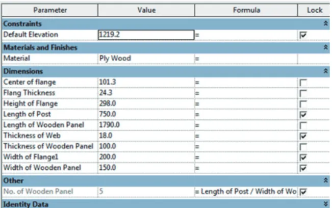
3.1.1 H-beam with wooden panel

The H-beam temporary structure is commonly used in the excavation projects. It is installed separately or attached to wooden panel and anchoring. Revit provides families with H-beam type, however, there are constraints to assign new parameters. For avoiding constraint problem, the H-beam is stretched and extruded. After sketching H-beam, next step is to assign design parameters to modify as per design Figure 1. Flow chart for 3D earthwork BIM temporary

structure design process

(4)

requirement. Similarly, wooden panel family is imported from the Revit database Design parameters for the wooden panel are assigned and linked with H-beam. Design parameters are assigned in such a way that with the increase of length, the number of wooden panels automatically increase. It helps the user to avoid increasing wooden panel length separately for each H-beam length. H-beam and wooden panel in combined form is shown in Figure 2, while Figure 3 shows the design parameters.
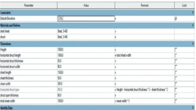
3.1.2 Sheet pile

Similar to H-beam, the sheet pile wall is used when the excavation having a depth range around 10-20 feet.

This type of temporary structure can be used for various projects. Revit library does not provide any family system for sheet pile so to create this temporary structure, sweep function of Revit family template is used. U-shaped sheet pile is sketched, and necessary parameters are assigned which can modify the shape if required. The sheet pile

design attached on generic face family template is shown in Figure 4 and the design parameters for the sheet pile are presented in Figure 5.

3.1.3 Bracing

Different types of temporary structures are used to support the surrounding structures and avoid falling soil in the excavation place. In case of shallow trenches, bracing are used. Three types of the bracing family are designed in this study which is mainly used for supporting soil while laying the underground facility. The factors considered for the selection of bracing are vibration from machines, traffic load, and slope stability. Main types of bracing are 1) Intermittent sheeting and bracing 2) Continuous sheeting and bracing Figure 2. H-beam+wooden panel temporary structure family

Figure 4. Sheet pile family design

Figure 3. H-beam+wooden panel temporary structure family design parameters

Figure 6. a) Trench shielding b) Intermittent sheeting c) Continuous sheeting

Figure 5. Sheet pile design parameters

(5)

3) Trench shielding. These structures are created using sweep functions in Revit and are presented in Figure 6.

Design parameters for continuous sheeting to modify its geometry is shown in Figure 7.

3.2 Earthwork Model Creation

It is essential to place the temporary structure on the generic face template for the proper visualization and quantity take-off calculation. For earthwork model in place function of Revit is utilized. The first step is to import the 2D drawings of the project into Revit. In next step, the generic solid model is created by using the model in place component function.

Revit also provides another model in place component from doors to wall opening which can be extruded or sweep according to design requirement. For representing earthwork model, a generic component in place is utilized.

The area is marked with a polyline and extruded to the desired height. After this temporary structure are attached to the face of the solid model, it is essential that BIM information system should be formed for drawing a model which represent earthwork. The information system should be in the horizontal and vertical division. The horizontal division represents the space information while vertical division represents the elevation information.

3.3 Quantity takes off calculation

The temporary structure is attached to generic model at 90-degree face angle as per design requirements mentioned in the drawing. It is feasible to divide the generic model of the project into the different regions for ease of quantity estimation of temporary structure. Quantity take- off calculation process can be performed by placing the temporary structure in the required region. Basic settings are required for calculation, for example, the selection of a generic model category in schedule/ quantities function. The filter can also be applied during the setting process. Table formatting and grouping should be performed according to requirement. The complete process of setting and formatting can be modified after achieving the results of quantity take- off which is performed through schedule/quantity option from view tab.

4. Case Study

A case study is conducted to check the complete process from 3D modeling of temporary structures to final model placement. Construction of an apartment complex is used as a case study. The apartment complex has twenty different apartment buildings. For the creation of the 3D model to represent earthwork BIM, the information system is defined for this particular project. Whole project information is properly arranged and is shown in Figure 9.

The apartment complex is divided into two regions naming region 1 and region 2; a region division plan is shown in figure 10. Both regions are further divided into the horizontal and vertical categories. The horizontal division is based on excavation and backfill area while vertical division is based on elevation difference.

Figure 8. Family category for model in place component

Figure 7. Continuous sheeting design parameters

(6)

Region 1 has six apartment buildings, and it is divided into four parts A1, A2, A3, and A4, which are further divided according to the elevation difference of the area.

Elevation of A1 is 306 m, and A21 is 311 m due to the slope variation at the construction site. The A2, A3, A4 are further horizontally divided into two portions according to backfilling and excavation region. A21 is building area where apartment building has to be constructed, and A22 area is backfill to building level. The vertical division is based on elevation as each region has at least two-level of excavation. First excavation underground parking level while the second level is ground level. Similar to region 1, region 2 is divided in to both horizontal and vertical direction.

The region 2 has a greater area than region 1, and it has sixteen apartment buildings. It has further three portions BI, B2, B3. Each area is horizontally divided into two segments:

building area and non-building area. Building area represents the excavation work, and then on-building area is backfill. In case of vertical division, B1 has two parking floor. The primary division is parking foundation level, floor height and building filling area in front of the building. The complete division map for region 2 is shown in Figure 11.

After defining complete BIM information system for the project, next step is to import 2D drawing layout of an apartment complex in Revit. Each region is sketched to generate a generic solid model for representing excavation and fill area. The model in-place component function is utilized to generate the model with various color so that each portion can be identified and visualized separately.

The image of a generic model of the region 1 (portion A41) as an example is shown in Figure 12. The brown color represents final level of excavation, and the upper green represents the area for floor height. Similarly, light green color represents the fill area in front of the building. For more understanding, the detail information building model is created along with its generic model. The orange color represents the backfill area.

Figure 9. BIM information system for region 1

Figure 11. BIM information system for region 2

Figure 10. Site map of region 1 and 2

(7)

According to the design, the temporary structure is not required all over the project site. Temporary structure regions are divided into three regions for calculating an accurate number of the temporary structure at each area.

The regions of the temporary structure are shown in Figure 13. H-beam with wooden panel and sheet pile temporary structure is attached to the face of a generic model, and its quantity is calculated.

The application of H beam and sheet pile is used in this case study for the verification of the proposed methodology.

The process places the elements automatically by predefined logic rather than manual manipulation. A rule might be created to ensure the placement of temporary structure elements along the soil and ensure that it starts below the base of excavation to the maximum height of the soil which require the support. This process removed the repetitive process of attaching the temporary structure along the length and depth of excavated soil. The parametric properties helped in the replication of same structure over the depth of earthwork. This process also aided the benefit by automatic calculation of number of structural elements

required for each region and further in the quantity calculation for each type of material. This methodology is useful for the project visualization, quantity calculation and error identification before the commencement of the project.

Two temporary structure family are used for the quantity calculation in this study. A total number of H-beam with wooden panel along with material required at all three regions in a tabulated form is shown in Figure 14. The number of the family set of H-beam with the wooden panel is required at region 1 is 58, for region 2 is 148 and for region 3 it is 192. The number of sheet pile in region 1 is 65, for region 2 it requires 159, and for region 3 it is 248. Similarly, the material of temporary structure can be computed through careful quantity take-off process.

This quick process of counting the required structural components result in significant cost and labor saving.

The manual and laborious quantity calculation method are eliminated through this automatic calculation.

5. Discussion

The 3D modeling of a temporary structure requires several heuristics to be considered which are as follows.

a) Complete geometric information of the temporary structures is essential for 3D modeling.

Figure 12. Earthwork generic model of A4 portion

Figure 13. Temporary structure for region 1 (left), region 2 (center), region 3 (right)

Figure 14. Quantity take-off for H-beam and

sheet pile revit family

(8)

b) The geometric structure should be locked from each side to avoid any change in temporary structure shape due to any error.

c) The parametric constraints that are not required for the project should be removed.

d) Color and material parameters can also be used as per design requirement.

e) Generic face template provides the ease to place the temporary structure on a solid model representing soil.

A content library for the temporary structure design is created in Autodesk Revit which includes Sheet pile, H beam and three types of trench shielding. These types of temporary structure were selected based on their field of usage and application. A separate Revit family for each type of temporary structure is created for use in earthwork model. The temporary structure design models for H-beam and Sheet pile are tested on a project for construction of apartment complex which involved the huge quantity of earthwork. These 3D models are used for the project visualization and resolve the conflict through clash detection. These BIM models improve the collaboration with a shared 3D model equipped with project details among key stakeholders. The quick and computerized method of counting the required structural components resulted in significant cost and labor saving. The temporary structure created by this parametric methodology can also be tested on a complex nature project considering different parameters. The authors have also identified the limitation in the current process. The placement of temporary structure along the soil is not fully automated, and the process can result in error especially at the corners with an abrupt change in earthwork direction. However, this limitation can be resolved by using Dynamo which can work as standalone or an add-in within Revit software. Dynamo provides a programming environment which helps to automate the task through parametric conceptual designing.

This parametric modeling procedure can also be adopted in the design of other building components to visualize the complex geometric shapes with varying parameters.

6. Conclusion

The 3D BIM model has made the exchange of information faster and easier for AEC industry. This study addressed the process of 3D BIM modeling of the temporary structure using the parametric technique. The complete 3D modeling process of earthwork temporary structure in Autodesk Revit platform is explained from family selection to parameters testing and its full implementation on a excavation project of apartment complex building. BIM information system is developed for case study, using generic solid model for the placement of temporary structure. The Revit families developed in this study can be utilized for any earthwork project with slight modification in the parameters according to design requirements and type of structure used. The use of parametric modeling speed up the design process and resultant 3D intelligent models are easy to understand as compared to 2D drawings. This process is also useful for the accurate quantity take-off for temporary structures which eliminates the tedious and cumbersome manual calculation process.

The temporary structure families designed in this research

are helpful for the designers to choose the type according

to site requirements and use for the project without getting

involved in the design process from scratch. The added

benefit of this study is improved collaboration among project

stakeholders through the use of shared 3D BIM models

and accurate material quantity calculation. The accurate

number of temporary structure for earthwork project is easy

to calculate using the implemented methodology. Basic

heuristics adopted are also defined along with the limitations

of the study. An automated system is required for placement

of temporary structures on large-scale projects to save

time which can be created through secondary development

program using Autodesk Revit platform. The future goal

is to use Dynamo as an extension of Revit software to

fully automate the temporary structure design process for

earthwork project.

(9)

Acknowledgment

This work is supported by the Korea Agency for Infrastructure Technology Advancement (KAIA) grant funded by the Ministry of Land, Infrastructure and Transport (Grant:

17SCIP-B079689-04)

References

Azhar, S., Khalfan, M., & Maqsood, T. (2012). Building information modeling (BIM): Now and beyond. Australasian Journal of Construction Economics and Building, Vol. 12, No.4

Azhar, S., Nadeem, A., Mok, J. Y., & Leung, B. H. (2008, August). Building Information Modeling (BIM): A new paradigm for visual interactive modeling and simulation for construction projects. In Proc., First International Conference on Construction in Developing Countries pp.

435-446.

Bryde, D., Broquetas, M., & Volm, J. M. (2013). The project benefits of building information modeling(BIM). International journal of project management, Vol.31, No.7, pp. 971-980 Demchak, G., Dzambazova, T., & Krygiel, E. (2009).

Introducing Revit architecture 2009: BIM for beginners.

John Wiley and Sons.

Fan, S. L., Kang, S. C., Hsieh, S. H., Chen, Y. H., Wu, C.

H., & Juang, J. R. (2009). A case study on constructing 3D/4D BIM models from 2D drawings and paper-based documents using a school building project. International Conference Computational Design in Engineering (CODE), pp.3–6.

Hare, W. L., Koch, V. R., & Lucet, Y. (2011). Models and algorithms to improve earthwork operations in road design using mixed integer linear programming. European Journal of Operational Research, Vol.215, No.2, pp.470- 480.

Ji, Y., Seipp, F., Borrmann, A., Ruzika, S., & Rank, E. (2010, June). Mathematical modeling of earthwork optimization problems. In Proc. of the International Conference on Computing in Civil and Building Engineering (ICCCBE).

Kim, K., & Teizer, J. (2014). Automatic design and planning of scaffolding systems using building information modeling.

Advanced Engineering Informatics, Vol.28, No.1, pp.68-80

Krygiel, E., Read, P., & Vandezande, J. (2010). Mastering Autodesk Revit Architecture 2011. John Wiley & Sons.

Lee, G., Sacks, R., & Eastman, C. M. (2006). Specifying parametric building object behavior (BOB) for a building information modeling system. Automation in Construction, Vol.15, No.6, pp. 758–776.

Nemati, K. M. (2007). Temporary structures, excavations and excavation supports. University of Washington.

Available from: courses. washington. edu/cm420/

Lesson5.pdf

Pardey, J., Roberts, S., & Tarassenko, L. (1996, January).

A review of parametric modelingtechniques for EEG analysis. Medical Engineering and Physics

Park, J. (2011). BIM-Based Parametric Design Methodology for Modernized Korean Traditional Buildings. Journal of Asian Architecture and Building Engineering, (November), pp.327–334

Smith, P. (2016). Project Cost Management with 5D BIM.

Procedia - Social and Behavioral Sciences, No.226, pp.193–200.

Slattery, K. T., & Slattery, D. K. (2013). Modeling Earth Surfaces for Highway Earthwork Computation Using Terrestrial Laser Scanning. International Journal of Construction Education and Research, Vol.9, No.2, pp.132–146

Šíma, J., & Seidlová, A. (2014). The Comparison of the Calculation of the Volume of the Foundation Pit. Procedia Engineering, No.91, pp.328–333

Sacks, R., Eastman, C. M., & Lee, G. (2004). Parametric 3D modeling in building construction with examples from precast concrete. Automation in Construction, Vol.13, No.3, pp.291–312.

Tang, J., Xi, P., Zhang, B., & Hu, B. (2013). A finite element parametric modeling technique of aircraft wing structures.

Chinese Journal of Aeronautics, Vol.26, No.5, pp.1202–

1210.

Volk, R., Stengel, J., & Schultmann, F. (2014). Building Information Modeling (BIM) for existing buildings—Literature review and future needs. Automation in construction, 38, 109-127.

Vysotskiy, A., Makarov, S., Zolotova, J., & Tuchkevich, E.

(2015). Features of BIM Implementation Using Autodesk

Software. Procedia Engineering, No.117, pp.1143-1152.

수치

Figure 5. Sheet pile design parameters
Figure 8. Family category for model in place componentFigure 7. Continuous sheeting design parameters
Figure 9. BIM information system for region 1
Figure 14. Quantity take-off for H-beam and  sheet pile revit family

참조

관련 문서

- In the future, the retail structure of power distribution may resemble the existing structure of the telephone industry.. Center for Power IT CENTER

Figure 8.4 The four basic feedback topologies: (a) voltage-mixing voltage-sampling (series–shunt) topology;.. (b) current-mixing current-sampling (shunt–series)

(i.e., how conceptual records and fields are represented at the internal level) – Structure of the stored database : change. (i.e., change in the

2) the process of underground mining generates a rock structure consisting of voids, support elements and abutment; mechanical performance of the structure is amenable to

It is expected to be used for forecasting and analysis of precipitation structure and characteristics of mesoscale system causing heavy rainfall using the

ƒ When the long-chain molecules in a polymer are cross-linked in a three dimensional arrangement the structure in effect becomes three-dimensional arrangement, the structure

• Accumulated microscopic damage develops into a crack or other  macroscopic damage

This section describes the overall structure of the diagnostic algorithm for abnormal situations using ANN. 6 illustrates the functional architecture of the diagnostic