CFRP로 제작된 적층각도를 가진 TDCB 구조물에서의 접착부의 파손에 관한 융합 연구
이동훈1, 조재웅2*
1공주대학교 대학원 기계공학과 학생, 2공주대학교 기계자동차공학부 교수
Convergence Study on Damage of the Bonded Part at TDCB Structure with the Laminate Angle Manufactured with CFRP
Dong-Hoon Lee
1, Jae-Ung Cho
2*1
Student, Department of Mechanical & Automotive Engineering, Graduate School, Kongju University
2
Professor, Department of Mechanical & Automotive Engineering, Kongju National University
요 약 본 연구에서는 CFRP를 적층각도 45도로 제작하고 구조용 접착제로 접착된 TDCB(Tapered Double Cantilever Beam) 시험편을 CATIA로 설계를 하였고, 유한요소해석 프로그램인 ANSYS를 이용하여 해석을 진행하였다. 연구 모델은 영국 산업 및 ISO 표준에 기초하여 설계하였으며, 모델 형상의 각도에 따라서 형상계수(m)를 변수로 설정하였다. 본 논문의 연구 결과로서, 모든 해석 시험편들 중에서 4° 인 경사 각도를 가진 시험편에서 최대 변형량은 12.628mm로 가장 높았으며 8°에서 12.352mm으로 가장 낮은 값을 각각 보였다. 또한, 최대등가응력은 그 각도가 6°에서 9210.3MPa가장 높았으며 8°에서 4800.5MPa로 가장 낮은 값을 각각 보였다. 본 연구 결과를 통하여 CFRP로 제작된 적층각도를 가진 TDCB 구조물의 파손데 이터를 확보할 수 있었으며, 본 연구결과를 토대로 얻은 CFRP로 접착된 TDCB 구조물의 파손데이터를 활용함으로서 실생 활에서의 기계나 구조물에 융합하여 그 미적 감각을 나타낼 수 있다.
주제어 : 융합, 탄소섬유강화플라스틱, 경사진 이중외팔보, 경사각, 적층각도, 정적 구조 해석, 등가응력
Abstract
In this study, CFRP was manufactured with the laminate angle of 45°. The specimen of TDCB bonded with the adhesive for structure was designed by CATIA and the analysis was progressed by using the finite element analysis program of ANSYS. This study model was designed on the basis of British industry and ISO standard and the configuration factor(m) was established with variable according to the angle of model configuration. As the study result of this paper, the maximum deformations at the specimens with the tapered angles of 4° and 8° become most as 12.628 mm and least as 12.352mm respectively. Also, the maximum equivalent stresses at the specimens with the tapered angles of 6° and 8° become most as 9210.3 MPa and least as 4800.5 MPa respectively. The damage data of TDCB structure with the laminate angle which was manufactured with CFRP could be secured through this study result. As the damage data of TDCB structure bonded with CFRP obtained on the basis of this study result are utilized, the esthetic sense can be shown by being grafted onto the machine or structure at real life.Key Words :
Convergence, CFRP(Carbon fiber reinforced plastic), TDCB(Tapered double cantilever beam), Tapered angle, Laminate angle, Static structural analysis, Equivalent stress*This research was supported by Basic Science Research Program through the National Research Foundation of Korea(NRF) funded by the Ministry of Education(NRF-2018R1D1A1B07041627).
*Corresponding Author : Jae-Ung Cho ([email protected]) Received October 4, 2018
Accepted December 20, 2018
Revised November 16, 2018 Published December 28 2018
1. 서론
자동차 업계에서는 최근 경량화 설계가 활발하게 진 행되면서 차체 프레임 바디의 소재가 중요하게 대두되고 있다. 일반적으로 프레임 제작 시에 사용되는 소재는 고 장력 강판을 주로 사용하고 있으며, 강성을 높이기 위해 서 초고장력 강판을 사용하게 되는데 강성과 강도가 높 아질수록 가공과정에서 어려움이 있다. 이러한 어려운 부분을 보완하기 위하여 탄소 섬유가 각광받고 있으며, 그 중에서 CFRP(Carbon Fiber Reinforced Plastic)이 주 목받고 있다. CFRP의 인장력은 철의 약 5배 정도 가지고 있고, 중량은 1/4로 줄어들면서, 강도는 10배, 탄성률은 7 배롤 강하며, 녹슬지 않아서 많은 곳에 핵심소재로 사용 하고 있다. 그러나 이러한 특성에 따라 CFRP는 차체 경 량화에 좋은 효과를 가질 수 있지만, CFRP로 제작 된 프 레임의 접합 방식에서 어려움이 작용하고 있다[1-4].기존 소재인 고장력 강판이나 알루미늄은 용접으로 접합이 가 능하나, CFRP는 용접에 많은 어려움이 있기 때문에 접 합 방식에 대해서 많은 연구가 필요하다[5-7].프레임 파 트를 볼트, 너트, 리벳 등으로 체결 시 차량의 경량화에 낮은 효과를 가지고 오기 때문에 구조용 접착제를 사용 하여 접합을 하며, 또한 설계적인 부분에서도 많은 영향 을 끼치므로, 시뮬레이션 해석을 통하여 구조물의 내구 성 및 취약적인 부분에 대해 미리 예측할 수 있다[8-13].
따라서, 본 연구에서는 단 방향의 특성을 가지고 있는 Unidirectional CFRP를 45도로 적층하여 구조용 접착제 로 접착한 TDCB 시험편을 각도에 따라서 설계를 하여 시뮬레이션 해석을 통하여 접착부분의 파손에 대해서 연 구 진행하였으며, 설계를 이용하여 항공기, 자동차 및 구 조물의 디자인과의 융합을 통하여 미적인 감각을 얻을 수 있다[14.15].
2. 본론
2.1 연구 모델 및 해석 조건
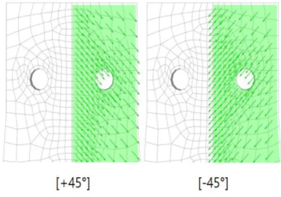
본 연구에서는 Fig 1과 같이 시험편의 적층각도는 Fig 2와 같이 한 Lamina를 [45°, -45°]로 설정하였으며, 적층 방법은 ANSYS내 에서 ACP(ANSYS Composite PrepPost)를 통하여 초기의 시험편 설정을 진행 하였다.
다음 Fig 2에서는 연구 모델로 형상계수인 m이 시험편 의 경사진 부분의 각도이며, Model 1, 2, 3, 4 들로서 각각
4, 6, 8, 10°로 설계하였고, 구멍의 크기와 시험편의 두께 는 각각 10mm와 5mm로 일정하게 하였다. 해석 조건으 로는 상단 부분의 시험편 구멍에는 윗 방향으로 Remote displacement를 적용하여 10mm만큼 강제 변위를 주었 고, 하단부분의 시험편 구멍에는 Cylindrical support를 적용하여 고정하였다. 연구 모델의 소재인 CFRP의 물성 치는 Table 1과 같으며, 이 소재의 구조는 단방향의 특성 을 가지고 있는 섬유로 되어 있기 때문에 좌표에 따라 각 x, y, z 방향의 물성치가 다르게 되어 있다.
Fig. 1. Laminate angle of CFRP
Fig. 2. Study model and analysis condition
Material Unidirectional Type CFRP
Density(kg/m
3) 1.57
Young's Modulus (MPa)
1.32x10
5(X) 8980(Y) 8980(Z) Poisson's Ratio
0.3(XY) 0.74(YZ)
0.3(XZ) Yield Strength (MPa)
1440(X)
51.72(Y)
51.72(Z)
Table 1. Material property of CFRP3. 해석 결과
본 연구에서는 소재가 단방향의 특성을 가지고 있는 소재인 Unidirectional CFRP를 이용하여 진행하였으며, 적층각도를 45°로 제작된 TDCB 시험편을 구조용 접착 제로 접합 부분을 접착하였다. 각 시험편들의 경사 각도 를 다르게 하여 접합 부분의 파손에 관한 기초 데이터를 얻기 위하여 연구를 진행 하였다.
(a) Model 1(Tapered angle: 4°)
(b) Model 2(Tapered angle: 6°)
(c) Model 3(Tapered angle: 8°)
(d) Model 4(Tapered angle: 10°)
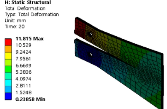
Fig. 3. Total deformations of TDCB specimens at models 1, 2, 3, 4
각 45°로 적층된 TDCB 시험편들의 시뮬레이션 해석 결과를 Fig 3의 그림을 통하여 보면 적층각도 45°로 된 CFRP의 TDCB 시험편들의 총 변형량의 값을 등고선을 통하여 나타낸 것이다. 각각의 모델들의 총 변형량의 최 댓값을 확인하여 보면 각도가 4°인 Model 1이 12.628 mm, 각도가 6°인 Model 2에서는 12.551 mm, 각도가 8°
인 Model 3는 12.352 mm이며, 각도가 가장 높은 10°인 Model 4는 12.52 mm의 결과 값이 나왔다. 각도가 8°인 Model 3 에서의 최대 변형량의 값이 가장 낮게 나왔으며, 각도가 4°인 Model 1에서는 가장 높은 값이 나왔다.
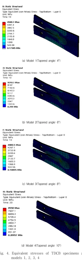
각 45°로 적층된 TDCB 시험편들의 시뮬레이션 해석 결과를 Fig 4의 그림을 통하여 보면 적층각도 45°로 된 CFRP의 TDCB 시험편들의 최대 등가응력의 값을 등고 선을 통하여 나타낸 것이다. 각각의 모델들의 등가응력 의 최댓값을 확인하여 보면 각도가 4°인 Model 1이 4940.3 MPa, 각도가 6°인 Model 2에서는 9210.3 MPa, 각 도가 8°인 Model 3는 4800.5 MPa이며, 각도가 가장 높은 10°인 Model 4는 8336.9 MPa의 결과 값이 나왔다. 각도 가 8°인 Model 3 에서의 최대 등가응력의 값이 가장 낮게 나왔으며, 각도가 4°인 Model 1에서는 가장 높은 값이 나 왔다. 각 시험편들의 최대 등가응력이 나타나는 부분을 확인 하여 보면, 크랙 부분에서 가장 높은 등가응력이 나 타나는 것을 확인 할 수 있었으며, 크랙이 진전되는 부분 에서 가장 취약하다는 점을 해석을 통해 알 수 있었다.
(a) Model 1(Tapered angle: 4°)
(b) Model 2(Tapered angle: 6°)
(c) Model 3(Tapered angle: 8°)
(d) Model 4(Tapered angle: 10°)
Fig. 4. Equivalent stresses of TDCB specimens at models 1, 2, 3, 4
4. 결론
본 연구는 적층각도가 45°인 Unidirectional CFRP인 복합재료를 TDCB(Tapered Double Cantilever Beam)로 설계 프로그램인 CATIA를 이용하여 설계 하여 유한요 소 해석을 이용하여 시뮬레이션 해석을 하였다. 시뮬레 이션 해석 프로그램은 ANSYS 를 사용하였다. 본 연구 결과는 다음과 같다.
1. 적층각도를 45°를 하여 Layer 별 해석을 진행하기 위해서는 유한요소 해석을 통하여 해석을 하기 에 는 많은 어려움이 있다. 그리하여 섬유의 두께와 적 층 각도를 지정하여 유한요소 해석을 통한 진행이 가능한 ANSYS 프로그램 내에서 ACP(ANSYS Composite PrepPost)를 이용하여 시뮬레이션 해석 을 진행하였다.
2. 각도에 따른 Unidirectional CFRP의 최대 변형량을 모델별로 비교 하여 보면 Model 3이 가장 낮게 나 타났으며. Model 1이 가장 높은 변형량을 가지고 있음을 알 수 있다. 각도가 4°인 시험편의 변형량이 가장 높은 변형을 나타내었고, 각도가 8°에서 가장 낮은 변형값을 보였다.
3. 각도에 따른 Unidirectional CFRP의 등가응력을 확 인하면 전체적으로 응력 집중이 접착 부분의 크랙 부분에서 크게 작용하고 있음을 알 수 있다. 시험편 이 접착되는 부분에서 박리가 일어났을 때 응력이 집중적으로 작용한다.
4. 전반적으로 해석 모델의 Unidirectional CFRP에서 발생하는 최대 등가응력을 각도별로 비교를 하여 보면 각도가 4°인 Model 1이 4940.3 MPa, 각도가 6°인 Model 2에서는 9210.3 MPa, 각도가 8°인 Model 3는 4800.5 MPa이며, 각도가 가장 높은 10°
인 Model 4는 8336.9 MPa의 결과 값이 나타나는 것을 확인 할수 있으며, Model 1이 가장 낮은 응력 이 나타났음을 알 수 있다.
5. 각도 별 TDCB 모델의 변형량 및 등가응력을 전체 적으로 확인하여 보았을 때, 각도가 8°에서 최대 변 형량 및 등가응력이 가장 낮은 값이 나왔으므로 내 구성이 다른 각도보다 좋은 것을 알 수 있었고, 변 형량도 가장 적었음을 알 수 있었다.
6. 본 연구의 해석을 종합적으로 확인하여 보았을 때, 적층 각도가 45°로 구조 설계를 한 Uidirectional CFRP을 적용하여 구조물을 설계 시 경량화의 효
과를 높일 수 있는 기초적인 데이터를 확보할 수 있으며, 본 연구결과를 토대로 얻은 CFRP로 접착 된 자동차, 항공기 및 구조물 설계 시에 파손데이터 를 활용함으로서 실생활에서의 기계나 구조물의 디자인과 설계를 통한 융합으로 그 미적 감각을 나 타낼 수 있다.
REFERENCES
[1] J. U. Cho. (2014). Structure Safety Analysis on Crack Propagation in Compact Tension Specimen. Journal of
the Korea Convergence Society, 5(1), 23-27.
DOI : 10.15207/JKCS.2014.5.1.023
[2] J. W. Park & J. U. Cho. (2017). Convergence Study on Composite Material of Unidirectional CFRP and SM 45C Sandwich Type that Differs in Stacking Angle. Journal
of the Korea Convergence Society, 8(7), 231-236.
DOI : 10.15207/JKCS.2017.8.7.231
[3] G. W. Hwang & J. U. Cho. (2017). Analysis Study on the Damage of Crack Happening with the Bending at CFRP Plate due to Stacking Angle. Journal of the Korea
Convergence Society, 8(3), 185-190.
DOI : 10.15207/JKCS.2017.8.3.185
[4] J. H. Lee & J. U. Cho. (2016). An Analytical Study on Crack Behavior Inside Standard Compact Tension Specimen with Holes. Transactions of the Korean
Society of Mechanical Engineers - A, 40(6), 531-537.
DOI : 10.3795/KSME-A.2016.40.6.531
[5] G. W. Hwang & J. U. Cho. (2017). Convergence Study on Durability Improvement due to Radius of Arch Type at CFRP Structure with Stacking Angle. Journal of the
Korea Convergence Society, 8(7), 219-224.
DOI : 10.15207/JKCS.2017.8.7.219
[6] J. H. Lee & J. U. Cho. (2016). Evaluation on Strength and Durability of Tensile Specimens of CFRP and Metal with Notches. Journal of the Korean Society of
Mechanical Technology, 18(6). 867-872.
DOI : 10.17958/ksmt.18.6.201612.867
[7] C. S. Seak & S. Y. Kim. (2000). Variation of the Fracture Resistance Curve with the Change of a Size in the CT Specimen. Transactions of the Korean Society of
Mechanical Engineers - A, 24(12), 2963-2971.
[8] G. W. Hwang, J. U. Cho & C. D. Cho. (2016). A Property of Crack Propagation at the Specimen of CFRP with Layer Angle. Transactions of the Korean Society of
Mechanical Engineers - A, 40(12), 1013-1019.
DOI : 10.3795/KSME-A.2016.40.12.1013
[9] T.A. Sebaey & E. Mahdi. (2014). Behavior of pyramidal lattice core sandwich CFRP composites under biaxial compression loading. Composite Structures, 116, 67-74.
DOI : 10.1016/j.compstruct.2014.05.014
[10] J. H. Lee & J. U. Cho. (2016). Convergence Technique Study of Durability Analysis due to the Track Pad Shape of Track Vehicle with Heavy Weight. Journal of
the Korea Convergence Society, 7(1), 177-182.
DOI : 10.15207/JKCS.2016.7.1.177
[11] M. S. Kang, H. S. Park, J. H. Choi, J. M. Koo & C. S.
Seok. (2012). Prediction of Fracture Strength of Woven CFRP Laminates According to Fiber Orientation.
Transactions of the Korean Society of Mechanical Engineers - A, 36(8), 881-887.
DOI : 10.3795/KSME-A.2012.36.8.881
[12] J. U. Cho. (2014). Analytical Study on Durability due to the Load of Artificial Knee Joint. Journal of the Korea
Convergence Society, 5(2), 7-11.
DOI : 10.15207/JKCS.2014.5.2.007
[13] J. H. Lee & J. U. Cho. (2016). A Study on Impact Fracture on CFRP Sandwich Composite and CFRP Sandwich Composite with Aluminum Foam Core.
Journal of the Korean Society of Mechanical Technology, 18(2), 214-219.
DOI : 10.17958/ksmt.18.2.201604.214
[14] J. Cao, K. Cai, Q. Wang & J. Shi. (2016). Damage behavior of a bonded sandwithc beam with corrugated core under 3-point bending. Materials and Design,
95(4), 165-172.
DOI : 10.1016/j.matdes.2016.01.083
[15] K. C. Park & M. S. Kim. (1994). Analysis of the Residual Strengths and Failure Mechanisms in Laminated Composites under Impact Loading. Journal of the Korean
Society for Precision Engineering, 11(3), 105-121.
이 동 훈(Lee, Dong-Hoon) [학생회원]
․2012년 3월 ~ 2018 2월 : 공주대 학교 기계자동차공학부(공학사)
․2018년 9월 ~ 현재 : 공주대학교 대학원 기계공학과(공학석사 과정)
․관심분야 : 기계 및 자동차 부품 설계 및 내구성 평가, 피로 또는 충 돌 시 동적 해석
․E-Mail : [email protected]
조 재 웅(Cho, Jae-Ung) [종신회원]
․1980년 2월 : 인하대학교 기계공학 과 (공학사)
․1982년 2월 : 인하대학교 기계공학 과 (공학석사)
․1986년 8월 : 인하대학교 기계공학 과 (공학박사)
․1988년 3월 ~ 현재 : 공주대학교 기계·자동차공학부 교수
․관심분야 : 기계 및 자동차 부품 설계 및 내구성 평가, 피로 또는 충돌 시 동적 해석
․E-Mail : [email protected]