*종신회원, 국립목포해양대학교
**정회원, (주)넷비젼텔레콤
접수일자 2010.10.11 수정일자 2010.11.29 게재확정일자 2010.12.15
논문 2010-6-11
Implementation of Radio Access Network for Mobile Backhaul Network
이동 백홀 네트워크용 Radio Access Network 구현
Chun-Kwan Park * , Han-Young Song ** , Byung-Chun Jeon **
박천관*, 송한영**, 전병천**
요 약 본 논문은 이동 통신 네트워크에서 기지국과 집중국사이에 설치되어 전송 비용을 줄여줄 수 있는 RAN
(Radio Access Network)전송 시스템을 구현하는 것이다. 이 시스템은 여러 세대의 이동 통신 기지국 개별적으로 사용 하는 전송 링크를 공유함으로써 전송 링크 수를 감소시켜 줄 수 있고, 지연 시간에 민감하지 않은 트래픽을 분류하여 그 트래픽을 Ethernet/IP 네트워크를 통하여 전달해 줄 수 있다.
Abstract
This paper aims to implement RAN(Radio Access Network) transmission system that can reduce the transmission cost by installing between mobile base station and base station controller. This system can reduce the number of transmission links by sharing the transmission link that the mobile communication stations of various generation use separately. This also can classify the traffics non-sensitive to delay time, and then transfer them through Ethernet/IP network.
Key Words :
RAN, IMA, Backbaul, PWE, TDMⅠ. Introduction
These days as mobile Internet growing explosively are based on wire infrastructure, ISP is installing wire network between mobile communication base stations.
This is why mobile Internet is not connected to entirely through wireless, but wireless is concerned in part of process that mobile Internet users connects to. As mobile communication base station is connected to transmission network through wire, if installing the wireless network infrastructure, the wire network has to be installed as closely as mobile communication base
station do.
Communication vendor are willing to installing their
own mobile communication network on a national scale
with the advent of individual broadband era. For this,
besides installing the mobile communication network,
the wire network infrastructure having the service
stability has to be installed simultaneously. it is
necessary to install the wire communication network
because high-speed is a vital element to provide mobile
communication service. So, mobile communication
vendors have increased investment in the wire
communication network to prepare the next generation
mobile communication, and installed the wire network
of light LAN level, called mobile communication
backhaul network between mobile stations to enhance
the service quality of increasing data
[2][3].
When mobile communication base station tries to connect to backhaul network, the required data rate has been increased and the cost of available gigabit Ethernet connection is getting cheaper. So, IP/Ethernet technologies has been used for backhaul. In the previous, mobile communication vendor has to pay much money to connect many base stations using TDM (Time Division Multiplexing) leased line. But they can save the costs considerably by using CES (Circuit Emulation Service) over lower price Ethernet network to transfer TDM signals
[1][4].
Therefore, to connect mobile communication base station to base station controller through hackhaul network, mobile communication base station has to connect to backhaul network. In this paper, we have designed and developed RAN transmission equipment to connect mobile base station to base station controller through backhaul.
Ⅱ. Mobile Backhaul Network
Carrier Ethernet is new version of Ethernet that has inherited many attributes from carriers such as SONET/SDH in service transfer and scale aspects for metro/backhaul application and removed self learning protocol and self control protocol. This carrier Ethernet is used for 3G/4G mobile backhaul network based on packet.
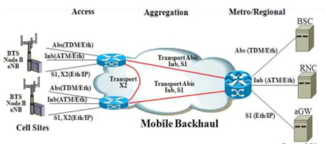
The area for mobile backhaul network ranges from the transmission equipment connecting cell sites to the transport aggregation equipment connecting central sites. Mobile backhaul consists of three sections, such as access network, aggregation network, and metro/regional network. Figure 1 shows the overall configuration of mobile backhaul network. Mobile backhaul can transport a diverse services, such as 2G, 3G, 4G, and LTE(Long Term Evolution)
[4][6][8].
Fig. 1. Mobile Backhaul Network 그림 1. 이동 백홀 네트워크
Table 1 describes the services that can transport through logical interface and mobile backhaul. Abis interface between 2G BTS and BSC can be based on TDM. And 3G Iub interface between Node B and RNC can be based on ATM/IMA and IPoEthernet. From logical point of view, Abis and Iub interfaces are entirely point-to-point connection. In LTE network, eNB has S1 and X2 interfaces. S1 interface is terminated at aGW. X2 interface is between eNBs and used for neighbor discovery, handover, and cell optimization. each eNB can communicate with its own neighbor directly. S1 and X2 interfaces are based on IPoEthernet
[5][7][8[11]Standard Interface Transport 2G Abis between BTS and
BSC TDM
3G Iub between Node Band RNC
ATM IMA over E1/T1, ATM over SDH
IPoEthernet LTE S1 interface between
eNB and aGW
IPoEthernet X2 interface between
eNBs Table 1. Interface and Service 표 1. 인터페이스 및 서비스
So, two type of basic connections has to be installed in mobile backhaul. one is a point-to-point connection between the transmission equipment connecting to cell sites and the transmission connecting to central site.
Another is a point-to-point connection between
transmission equipments/interfaces connecting to two
eNB. And, for rich potential applications, unicast and multicast services has to be provided in mobile backhaul that can use the network bandwidth effectively.
Ⅲ. RAN Transmission System
As mobile backhaul network connects mobile communication BS to BSC, it delivers the bandwidth requirement of diverse technologies, such as 2G, 3G, 4G and WiMAX. And PS and TDM are used for mobile backhaul network. This paper is to develop RAN transmission equipment for cell site and carrier Ethernet services. In mobile backhaul network, any kind of traffics can be transported through the packet network, such as MPLS-TP and PPB-TE.
Fig. 2. The overall configuration 그림 2. 전체 구성도
Figure 2 shows the overall configuration of network.
As communication vendor tries to install their own mobile communication network at the advent of personal broadband era, besides installing the mobile communication base station, they also have to install the wire network infrastructure having service stability
[4][10]. Specially, As the fast rate is required to provide the smooth mobile communication service, it is essential to install the wire network. So, vendor have invested in the wire network for the next generation mobile communication, and installed the wire network
of optical LAN level such as mobile backhaul between base stations to copy with the increasing data traffics.
In this backhaul network, BS should be interfaced with the backhaul network to connect BS to BSC through the backhaul network.
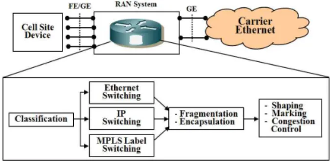
Figure 3 shows the packet service of RAN system.
RAN system has two interfaces, such as UNI(User-Network Interface) and NNI(Network Network Interface)
[9][10][12].
Fig. 3. The packet service 그림 3. 패킷 서비스
UNI is interface between cell site and RAN system and NNI is interface between RAN system and backhaul network. When the packets arrive at RSN system from cell site, these packets are classified into the specific flow according to the classification rule.
The classified packets are assigned to the switching part, such as Ethernet, IP, or MPLS. As Ethernet frame, IP packet, or ATM cell in the switching part are segmented and then encapsulated, they are transferred to backhaul network. QoS functions, such as shaping, marking, and congestion control, are assigned to the encapsulated traffics.
Figure 4 shows TDM/ATM services of RAN
system. RAN system processes two kind of signals,
such as TDM and ATM. TDM signal is encapsulated
through SAToP or CESoPSN and clock recovery
function is performed. ATM signal is distributed to E1
links through IMA function, and then the distributed
signals to E1 links are encapsulated
[9][10][13].
Fig. 4. TDM/ATM service 그림 4. TDM/ATM 서비스
IⅤ. Implementation of RAN System
RAN system can reduce about 30% of the transmission links by distributing the traffics to several E1 links through IMA technology, and accommodate the existing TDM/ATM equipments as well as the base station ones based on IP. And as this system can also accommodate the base station equipments of next generation 3GPP LTE based on IP, it can transfer the traffics through the packet switched network.
Figure 5 shows the block diagram of RAN system.
This system supports several interfaces that can accommodate 2G/3G/4G base station equipments, and transfer the traffics through the diverse transmission paths. This system has several interfaces, such as HDLC, TDM, ATM, and Ethernet, and can transfer the traffics through E1 dedicated line, IP network, or wireless bridge.
In this figure, RAN system consists of two E1/T1 modules (one E1/T1 module has 8ports), 4 port 100Base-Tx Ethernet interfaces, two port GbE interfaces for UNI (one is RJ-45 connector, another is GbE optic connector), two port GbE interfaces for NNI (one is RJ-45 connector, another is GbE optic connector), two port GbE interface for UNI and NNI respectively as option, one serial port for console, and one 100Base-Tx port for management.
Table 2 shows the interface configuration of RAN system. they are classified into UNI, NNI, and management. RAN system can transfer the traffics
simultaneously through several paths, and also them through several E1/T1 links using ATM IMA function.
items Function
UNI (User Network
Interface)
- T1/E1 Interface : Maximum 16 Ports(8 ports : Option)
- 100Base-Tx : 4 Ports
- GbE(1000Base-T) : 4 Ports (2 Ports : Option)
NNI (Network Network
Interface)
- GbE(1000Base-T) : 4 Ports (1000Base-T, 1000Base-Sx/Lx, 2 ports (option)) Table 2. Interfaces of RAN System
표 2. RAN System 인터페이스
Fig. 5. RAN System block diagram 그림 5. RAN 시스템 블럭도
Figure 6 shows the board configuration of RAN system. This board consists of Gigabit Ethernet module (2ports for NNI (Uplink), 2ports for UNI (Downlink)), TDM interface module, 100Base-Tx for management, one serial port for console, and Gigabit Ethernet and TDM interface modules as option.
Fig. 6. Board Configuration 그림 6. 보드 구성도
item Function
cell site data
transmission - Ethernet Traffics
- ATM transmission(T1/E1,ATM,IMA,STM-1) Encapsulation PWE3
- CESoPSN (RFC5086), SAToP(RFC4553) - ATM Encapsulation(RFC4816, RFC4717) - MPLS Encapsulation(RFC4717, RFC4448) - IEEE1588v2 Timing Synchronization Encapsulation
- Q-in-Q, MAC-in-MAC Encapsulation, MPLS-TP, PBB-TE
- Link OAM (IEEE902.1ah), CFM (IEEE802.1ag), Y.1731
Others - CoS & QoS functions - Static IP routing
- System management function
Table 3. main technologies표 3. 주요 기술
Figure 7 shows the software configuration of RAN system. This system use the network processor of Wintegra, and the software architecture is extended from data plane to control one and host processor environment. In host processor environment, multi-protocol communication platform(WinPath) has to be integrated into the overall system architecture.
For this, Network processor provides modular, object-oriented API. As device driver interface(WDDI) has software architecture based on host, the all configurable WinPath features can be accessed through ANCI-C. That also treats hardware and data path software(DPS) in a uniform type
[12][14][15].
RAN system software consists of control path and data path softwares. Control path software consists of OAM, control protocol, and system application. Data Path Software(DPS) is the configuration drivers based on hardware interface, and performs most of L2/L3 protocol processing functions. Control Path Software(CPS) can communicate with data path one through API. CPS services are chip/board initialization and driver/API implementation. And CPS applications are RTOS (Real Time Operating System), ATM signaling stacks, host-level PPP services (authentication), host-level IP services (TCP. UDP.
control plane routing protocols). Configuration drivers includes interworking, QoS, and L2 protocols.
Fig. 7. Software Concept 그림 7. 소프트웨어 개념
Ⅴ. Test the performance of RAN System
RAN system is the equipment that connects mobile communication base station to backhaul network in the long run. Test items includes consists of T1/E1 link aggregation (IMA : Inverse Multiplexing ATM), Pseudo Wire Emulation over IP, Pseudo Wire Emulation over long reach wireless, and QoS & IPsec.
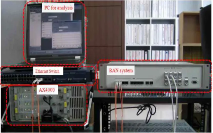
Figure 8 shows the configuration to test the function and performance of RAN system. This configuration consists of the computer to analysis the format the received packet,
Fig. 8. Test Configuration of RAN 그림 8. RAN 시스템 시험 구성도
Ethernet switch that configures the loopback and
has the mirror function in receive side, AX400
equipment that generates TDM frame and then
analysis the received TDM frame, RAN system, and
N2X equipment that generates Ethernet frame and then analysis the received Ethernet frame. N2X generates Ethernet frame and then analyzes the received Ethernet frame from Ethernet. N2X also generates the background traffic to test the performance of TDM signals.
Figure 9 shows the throughput of RAN system. In this test, only Ethernet frame is generated and then analyzed. The test is done per packet size, such as 64, 128, 256,512, 1,024, and 1,490bytes. For this packet sizes, the test is done for each encapsulation, such as no, MPLS, IP/UDP, and MEF8. In this chart, throughput is almost same for each encapsulation.
Fig. 9. Processing performance 그림 9. 처리 성능
Figure 10 shows the inner delay of ATM. N2X generates the background traffic for system load. For this background traffic. AX4000 equipment inputs ATM traffic into E1 link, restores ATM cell, and then encapsulates the restored ATM cell into carrier Ethernet frame. the delay is measured according to the background load for this operation.
For this test, the background packet size is 128bytes, and ATM cell rate is 4,528cells/sec (1920kbps). The test is performed for 3 Encapsulation types, such as UDP/IP, MPLS, and MEF E-line service. Load means the used one of total 1Gbps link bandwidth, and the delay time is measured per encapsulation type. For IP/UDP encapsulation, the delay variation is high for low load, and stabilized for about 40% load. For MPLS
encapsulation, the delay is maintained and then increased rapidly from 80% load. For MEF E-line service encapsulation, the constant delay is maintained for all loads.
Fig. 10. Inner delay of ATM 그림 10. ATM 내부 지연
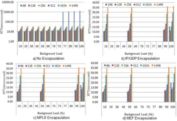
Figure 11 shows the inner delay of IP Packet. This contains several type of encapsulations, such as no, IP/UDP, MPLS, and MEF8. Packet size are 64, 128, 256, 512, 1024, and 1,490 bytes.
Fig. 11. Inner delay of packet 그림 11. 패킷 내부 지연
(a) shows no encapsulation. In this case, delay is
increased dramatically for 75%~100% load at packet
size of 64bytes. This is related to the decrease of
throughput for that load. (b) shows IP/UDP
encapsulation. In this case, overhead consists of three
headers, such as 14bytes Ethernet, 20bytes IP, and
8bytes UDP. delay is constant for all loads but
increased dramatically for 75%~100% load at packet size of 64bytes. (c) shows MPLS encapsulation. In this case, overhead consists of three headers, such as 14bytes Ethernet, 4bytes MPLS outer label, and 4bytes MPLS inner label. delay is constant for all loads but increased dramatically for 75%~100% load at packet size of 64bytes. (d) shows MEF8 encapsulation. In this case, overhead consists of three headers, such as 14bytes Ethernet, 4bytes outer VLAN tag, and 4bytes inner VLAN tag. delay is constant for all loads but increased dramatically for 75%~100% load at packet size of 64bytes.
Ⅵ. Conclusion
In this paper, RAN system is the equipment to reduce the cost of transmission link between base station and central office. So it can reduce the number of transmission links through the statistical multiplexing by having the transmission link shared that base station equipment of many generations uses independently. And it separates the traffics non-sensitive to delay and then delivers them through low-cost transmission network. it ca reduce Capex and Opex of RAN network by having IP/MPLS network or Ethernet wireless bridge used as RAN transmission network of mobile communication network.
In near future, mobile communication network based on mainly TDM will be all IP/Ethernet one. Ethernet and TDM traffics will be transferred through packet switched network. And if HSDPA and Wibro technologies are applied to, it is time when mobile backhaul network is changed to transfer IP traffic. So technologies that can integrate voice, data, and IP packet and then transfer them will make a contribution to the development of mobile backhaul network.
참 고 문 헌
[1] (주)넷비젼텔레콤, “E-PON 기반 데이터 및 TDM (T1/E1) 전송 시스템 개발”, 산업자원부 최종보고 서, April 2007.
[2] 윤지욱, 유제훈, “패킷-광 전송 시스템 기술 동향 분석”, 한국전자통신연구원 주간기술동향 통권 1405호, July 2009.
[3] 주성순, 안계현, 이유경, “차세대 네트워크 인프라 를 위한 캐리어 이더넷 기술”, 전자통신동향분석 제 21권 제 6호 Dec, 2006.
[4] (주)넷비젼텔레콤, “2G/3G/4G 이동망을 위한 RAN(Radio Access Network) 전송장치 개발, 중 소기업 기술개발 지원 사업 최종보고서, JUL.
2010.
[5] http://www.trainercomm.com/.../brocade/, "Carrier Ethernet Technologies Comparison", BROCADE, Feb. 2010.
[6] Huawei Technologies Co., Ltd, “Technical White Paper for PWE3“,
httpd://www.huawei.com/products/datacomm/pdf/
[7] NEC Corporation, "Mobile Backhaul Evolution for deploying Mobile Generation Networks (Mobile GEN), White Paper, Feb. 2007.
[8] UTStarcom.inc, "3G/LTE Mobile Backhaul Network MPLS-TP based Solution", White Paper, 2009
[9] A. Vainshtein, Ed, YJ. Stein, Ed, "Structure -Agnostic Time Division Multiplexing (TDM) over Packet (SAToP)", RFC4553, June 2006.
[10] A. Vainshtein, Ed., I. Sasson, E. Metz, T. Frost, P. Pate, "Structure-Agnostic Time Division Multiplexing (TDM)", RFC5086, Dec, 2007.
[11] Ran Avital, "Mobile Backhaul Network Migration -Building an Evolution-Ready Backhaul", Ceragon Network, White Paper, 2007.
[12] Wintegra, "WDDI Bridge Tutorial", May 2009.
[13] Wintegra, "Confidential Proprietary Access Packet Processor Routing and Interworking Specification IW Book", Rev 0.78, Feb. 2009.
[14] Wintegra, "Access Packet Processor WinPath
WinComm & DPS Specifications L2 Book" Rev
0.74l, Feb. 2009.
※ 본 연구는 중소기업기술개발지원사업(주관기관 : (주)넷비젼텔레콤)의 지원으로 수행된 것입니다.
저자 소개 박 천 관(평생회원)
ㆍ2009년 제 9권 5호 참조
송 한 영(정회원)
ㆍ2009년 제 9권 5호 참조
전 병 천(정회원)
ㆍ2009년 제 9권 5호 참조