Analyze on Heat-sink of 20Watt Class LED Lamp using COMSOL
Ik-Soo Eo
1*1Dept. of Electrical Engineering, Honam University
COMSOL을 이용한 20W급 LED램프의 방열 해석
어익수
1*1호남대학교 전기공학과
Abstract This thesis is about Heat-sink design which is considered as the biggest problems for commercialization of LED lighting and suggests how to solve the problems though analysis on heat-sink using COMSOL. The temperature difference after simulation value and modelling was 10℃ by Transient analysis of Heat Transfer Module which is in the COMSOL Multiphysics. The result approximated the object which is close to actual lighting, when various elements are used according to temperature change of interior and exterior surroundings LED lighting is set up.
요 약 본 논문은 LED조명기구의 상용화에 가장 큰 문제로 제기되는 방열설계에 관한 논문으로서, COMSOL을 이 용한 방열해석을 통하여 문제해결의 방법을 제시한다. COMSOL Multiphysics에 있는 Heat Transfer Module의 Transient Analysis를 활용하여 해석한 결과, 시뮬레이션 값과 시작품 제작 후 측정 온도와의 차이가 10[℃]이하로 도 출되었으며, Led Lamp가 설치되는 실내․외의 환경조건의 온도변화에 따른 제 요소들을 잘 활용하면 실제 작품의 목 표치에 근접하는 결과를 얻을 수 있음을 확인할 수 있었다.
Key Words : LED, COMSOL, Heat-sink, MCPCB, CF-d.
*Corresponding Author : Ik-Soo Eo([email protected])
1. Introduction
The core of LED lamp development is considered as Lenz-design, Power Source, and Heat-sink.
Commercializing and Merchandising is possible only if a product has economic value. However, efficiency of LED semiconductor is 120 lm/w and LED has enough economics value in terms of price. The most difficult part of LED lamp is Heat-sink. It is because as temperature becomes higher, the lamp life reduces rapidly and the efficiency declines as well. Therefore, temperature of the LED semiconductor is very critical issue[1]. As MCPCB is developed for solving this problem, researches on sufficient materials with sufficient thermal conductivity are going on, but it is too early to adopt it with economic
value and external shape.
Social needs for high illuminance are growing, so LED capacity becomes enlarging, and more various methods are being suggested now to solve the heat problem which is maximizing. There are many refrigeration methods including aluminum Heat-sink plate usage method as old method, and secondly refrigeration method adding fan, refrigeration method with fan rotating cooling water, refrigeration method with Peltier module, heat emission method by Heat-pipe.
There isn't a lot of methods surpassing natural Heat-sink which need large surface area and the fact is the very important. Consequently, in case of Heat-sink designing, it is designed to applicable method like Fig.
1 and would select the method to suitable for installation
environment and demonstration of applicable method should be done and method suitable for setup surroundings should be selected. Simulations should be repeated as well. This thesis makes it possible to solve Heat-sink analysis using COMSOL.
Optics
&fixture Monitoring
Power supply
Radiation Network
Heat Heat
Radiation
[Fig. 1] Figure title[2]
2. Thermal Transmission Analysis 2.1 Thermal Conduction Rate and Thermal
Diffusivity Thesis
The following condition governs thermal conduction rate in the normal state to analyze temperature distribution on thermal movement and diffusion of LED lamp. Under the law of energy conservation, thermal conduction rate of each direction of x, y, and z is represented as following Fig. 2 by Taylor series[3].
[Fig. 2] Conceptual diagram of thermal movement and diffusion
(1)
(2)
(3) There can be energy source related to thermal energy incidence percentage inside medium, and it can be represented as
(4)Also, energy amount change of interior thermal energy is possible by material inside volume and is represented as
(5)So, general form of energy preservation demand is in the following.
(6)where Ein is the energy added or transferred to a system; Eg is the energy converted to thermal energy manifested as heat; Eout is the energy transferred out of a system or released to the ambient; and Est is the energy stored in the system.
When we arrange this and thermal conduction rate under the Fourier`s Law, a general type of thermal diffusion equation is
(7)
In here, (ρCp)s are respectively the volumetric heat capacities of the fluid.
If thermal conduction rate k is constant and its condition is set as normal state, the above becomes simple as below.
(8)
(T: temperature, Cp: specific heat, k: thermal conduction coefficient)
Heat transform process is possible to make a quotient equation through quantification and this equation is used in calculation of energy amount within unit time. Quotient equation for heat transform would be arranged by Fourier’slaw and interprets various physical phenomena by COMSOL Software which could be modeling and simulating under CAD environment. Embedded control equation could be modeling through numeric analysis which is used to partial differential equation for various physical phenomena.
2.2 Multiphysics Modeling
As a experiment condition, using Transient analysis of Heat Transfer Module in the COMSOL Multiphysics, 1[W] level and high luminance LED 20 in the MCPCB with width 160mm and depth 50mm is dispositioned as Fig. 3 and search for thermal flow and distribution.
Library material of the MCPCB is used as aluminum, boundaries conditions are summarized in the following table 1.
Description Value Unit
K(isotropic) 160 W/(m∙K)
Density 2,700 kg/㎥
Heat capacity at constant
pressure 900 J/(kgㆍK)
Temperature 300 oK
[Table 1] MCPCB Boundaries conditions
[Fig. 3] Subdomains setting(MCPCB)
In Fig. 4, library material of LED is chosen as silicon made by 'C' corp. for experiment, as for 1Watt class LED material value in the following Table 2 is used.
Description Value Unit
K(isotropic) 163 W/(m∙K)
Density 2,330 kg/㎥
Heat capacity at constant
pressure 703 J/(kgㆍK)
Temperature 420 oK
[Table 2] LED Boundaries conditions
[Fig. 4] Sub-domains setting(LED)
As for boundary condition, maximum temperature of aluminium in the MCPCB is set to 300[°K], and LED temperature is decided as 420[°K].
Meshes of Fig. 5 is Free Mesh and predefined mesh size is normal and its basic form is triangle, X- direction scale factor is 1.0, Y- direction scale factor is 1.0, and Resolution of geometry is set by 10 as dense value as possible.
[Fig. 5] Mesh
3. Analysis Result
There are two analysis methods. The first method is to analyze temperature and speed pressure from peak to stable state, and the second method is to analyze value
temperature, speed and pressure.
This analysis is to confirm astringency including temperature, pressure and density in each item by interpretation of stable state, and 2D and 3D analysis is used for LED thermal transmission analysis[3].
3.1 2D Design Analysis
Fig. 6 is Surface Plot's result value by analyzing thermal transmission, when section is cut by 2D. The center part of LED contains high heat temperature of 335[°K] and the PCB part has low temperature gradually by absorbing heat from aluminum with surrounding temperature of 299[°K].
Max:338 335 330 325 320 315 310 305 300 Min:300
[Fig. 6] 2D Surface plot of heat flux
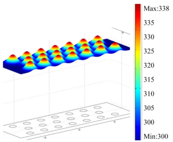
3.2 3D Design Analysis
Result value of 3D Surface Plot as Fig. 7 shows that high heat produces from the cental part of LED, and temperature decreases in a gradual way as Aluminium, the PCB part, absorbs heat. To obtain data in each level, checking data saved per step after analysis makes possible to investigate thermal distribution state.
Max:338 335 330 325 320 315 310 305 300 Min:300
[Fig. 7] 3D Surface plot of heat flux
Contour line is drawn with heat produced from LED and the central part is more denser in the contour line with a lot of heat than the circumferential part with lower temperature distribution.
Max:338 330 328 326 324 322 320 318 316 314 312 310 308 306 304 302 300 Min:300
[Fig. 8] Contour plot
We can have these result with quantitative value as well as with qualitative value. Cross-Section Plot Parameters are shown in Fig. 8. If we chose a certain point of the above and drag it to below in the temperature characteristic graph of Fig. 9, we can exactly recognize its temperature characteristics[4].
When Arc-Length is 1, centigrade stabilizes around 5 0℃. Below 90℃, LED functions normally, so we can achieve satisfactory result.
55 50 45 40 35 30 25 20
[Fig. 9] Cross-Section plot parameters
4. Conclusion
It was found that temperature of LED lamp stabilized at 50℃ by analysis on LED heat transmission problems using COMSOL. However, there are various Material Factors for precise analysis and verification and the following procedures were carried out with experiments.
1. In case comparing COMSOL and CF-d as heat-sink program, simulation is simple but the property of material is variable, so input of exact numeral value is difficult in COMSOL while simulation is complicated and takes much time to acquire its method in CF-d. Both programs were achieved satisfactory result in heat-sink analysis with 10℃
difference.
2. As for general analysis, thermal energy amount and temperature condition was chosen with data of producer company and experiment data, and thermal experiment about actual model and its result are made use of achieving thermal energy amount and lost amount of LED and heat transmission value by MCPCB.
3. Law Data should be established using data from experiments and analysis conditions, and material property of analysis should be adopted about various experiment parameters. Based on the law data, the best Model can be accomplished.
4. If optimization experiment of complete product and simulation analysis are proceed as well, it helps to reduce time consumption and experiment times for prototype. Consequently, it is good for to produce more improved condition than optimization method.
References
[1] I. S. Eo, "Research on Heat-Sink of 40Watt LED Lighting using Peltier Module", Journal of the Korea Academia-Industrial cooperation Society, Vol. 8, No. 4, pp. 733~737, Aug. 2007.
[2] J-B. Rouffet, S. Bhosle, G. Zissis, "Using COM- SOL Multiphysics to Modelling High Pressure Discharge Lamps" University Paul Sabatier, COM- SOL Users Conference 2006.
[3] I. S. Eo, "Analysis of the Heat Radiation of LED Light Fixture using CF-design“ Vol. 9, No. 6, pp.
1565~1568, Dec. 2008.
[4] Remo Winz1, Alejandra de los R´ıos Gonzalez2,
“Simulation of a Micro-Analytical Device for Adsorbing Substances“, Fluid Research Centre J¨ulich, Institute of Biotechnology, COMSOL Users Conference 2007.
Ik-Soo Eo
[Regular Member]• Feb. 1986 : Department of electrical engineering, Seoul National University of Technology (BS)
• Feb. 1996 : Department of electrical engineering, Hanyang University (MS)
• Feb. 2008 : Department of Computer application engineering, Seoul University of Venture &
Information(Ph. D.)
• Feb, 1998 ~ Currently : Associate Professor of electrical engineering department at Honam University
<Research Interests>
Electrical Facilities, Lighting and design, Heat-sink