• 검색 결과가 없습니다.

Quasi-Distributed Water Detection Sensor Based On a V-Grooved Single-Mode Optical Fiber Covered with Water-Soluble Index-Matched Medium

N/A
N/A
Protected

Academic year: 2021

Share "Quasi-Distributed Water Detection Sensor Based On a V-Grooved Single-Mode Optical Fiber Covered with Water-Soluble Index-Matched Medium"

Copied!
5
0
0

로드 중.... (전체 텍스트 보기)

전체 글

(1)

http://dx.doi.org/10.5369/JSST.2015.24.1.1 pISSN 1225-5475/eISSN 2093-7563

Quasi-Distributed Water Detection Sensor Based On a V-Grooved Single-Mode Optical Fiber Covered with Water-Soluble Index-Matched Medium

Dae Hyun Kim and Kwang Taek Kim

+

Abstract

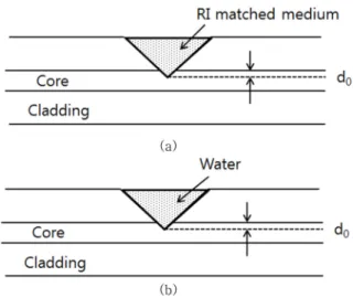
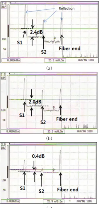
The V-grooved single-mode fiber in which a surface part of the core was removed was investigated as a quasi-distributed water detec- tion sensor. In the normal state, the V-grooved region is filled and covered with a specific RI (Refractive Index)-matched medium, and the sensor experiences minimal optical loss. As water invades the V-grooved region, the material is dissolved and removed, and a con- siderable optical loss occurs owing to the large RI difference between the fiber core and water. The experimental results showed the feasibility of the device as a sensor element of the quasi-distributed water detection sensor system based on general optical time domain reflectometry (OTDR).

Keywords: Fiber optical sensor, Water detection sensor, V-groove fiber, OTDR

1. INTRODUCTION

Fiber optic sensors offer many attractive benefits such as small size, low weight, high resolution, and high immunity to electromagnetic waves, as well as ease of multiplexing and distributed sensing. There are various methods to detect the external liquid medium around optical fiber through evanescent wave coupling including the cladding-etched FBG [1], the tapered optical fiber [2], the side-polished optical fiber [3], and the etched optical fiber [4]. The complicated fabrication process and the high cost of those sensors restrict wide use of the quasi-distributed sensor system. Of course, research on the water detection sensor based on the bending loss of optical fiber caused by a swelling material has been reported. However, it needs a long operating time because the swelling process in the water [5,6] is time consuming, and the structures are bulky.

Recently, the V-grooved fiber as an element of a multipoint sensor system has been reported [7]. The magnitude of the optical loss depends on the depth of the V-groove and the refractive index (RI) of the covering medium. For use of the V-grooved fiber as a

quasi-distributed water detection sensor, both a small optical loss in the normal state and a high-contrast optical signal for the water invasion are required. From these points of view, air (no medium) is an undesirable covering medium of the V-grooved region in the normal state, because the sensor signals acquired using optical time domain reflectometry (OTDR) for the water covering were not clearly distinguished from those for air covering, in spite of the large RI difference between the two materials. Furthermore, under the air covering, the device experiences a high optical loss.

The optical loss of the sensors in the normal state limits the maximum sensing point for the multipoint sensing system based on OTDR. Therefore, we need to employ a covering medium other than water.

In this study, for application as an element of a quasi-distributed water detection sensor system based on OTDR, we have investigated a technology for acquiring a high-contrast signal against the normal state signal when water invades the V-grooved fiber. We found that if the RI of the covering medium on the V- groove is similar to that of the optical silica fiber core, a negligible optical loss occurs, whereas air or water on the V-groove causes considerable optical loss. Therefore, an RI-matched medium is suitable as the covering medium of the V-grooved region of optical fiber because it causes minimal optical loss. The sensor is designed so that as water invades the V-grooved region, the RI match medium is dissolved.and the covering medium is replaced with water. As a result, the high optical loss can be easily monitored by OTDR.

The fabrication process of the V-groove is very simple, because Department of Electronic Enginnering, Honam University

417, Eodeung-daero, Gwangsan-gu, Gwangju, 506-714, Korea

+

Corresponding author: [email protected]

(Received: Dec. 22, 2014, Revised: Jan. 7, 2015, Accepted: Jan. 8, 2015)

This is an Open Access article distributed under the terms of the Creative Commons Attribution Non-Commercial License(http://creativecommons.org/

licenses/bync/3.0) which permits unrestricted non-commercial use, distribution,

and reproduction in any medium, provided the original work is properly cited.

(2)

the V-grooves on a single-mode fiber can be inscribed using a dicing machine for semiconductor wafer cutting. Multiple V- grooves along a single-mode fiber can be applied for a quasi- distributed water detection sensor system based on OTDR.

2. SENSOR STRUCTURE AND OPERATION PRINCIPLE

The schematic structure of the proposed V-grooved single-mode fiber is shown in Fig. 1. The side of the fiber was removed, and the edge of the V-groove reached into the core. However, much part of the core remained. In the normal state, the V-grooved region is filled with an RI-matched medium whose refractive index is close to that of the core of the single-mode fiber as shown in Fig. 1(a). If water invades the V-grooved region, the RI- matched medium is solved, and the covering medium is replaced with water as shown in Fig. 1(b).

The optical mode of the fiber was strongly dependent both on the groove structure and on the RI of the covering medium [5].

Using the beam propagation method (BPM), we have investigated the transmission characteristics of the V-grooved single-mode fiber. In the simulation, the optical fiber of the system was used as a single-mode optical fiber for standard optical communication. The core radius, the core RI (n

co

), and the cladding RI (n

cl

) were assumed to be 4.0 um, 1.450, and 1.444, respectively, at the wavelength of 1550 nm.

For ease of analysis, we assumed the V-groove angle between the two surfaces to be 90

o

and the depth of the V-groove (d

0

) to be 3.0 um. Fig. 2 shows the optical mode propagation in the z

direction for three covering media: air, water, and the RI-matched medium. For air and water, the optical mode arrives at the V- groove, is strongly affected by it, and is abruptly changed as shown in Fig. 2(a) and (b). As a result, a part of the optical power may leak out from the core, whereas with the RI-matched medium, the optical mode is hardly influenced by the V-groove, as shown in Fig. 2(c).

Fig. 3 shows the variation of the guided mode power along the V-groove the optical fibers for three covering media. When no medium (air) was present in the V-groove, the mode was strongly affected by it, and as a result, much of the guided mode power leaked out. When water covers the V-grooved region, a slightly smaller optical loss occurs than with the air covering. If an RI- matched medium is filled in the V-groove, the guide mode profile hardly changes, and no considerable optical loss occurs, as shown in Fig. 3.

We have calculated the optical transmittance as the refractive indices of the covering media change, and the results are shown in Fig. 4. The transmittance is the ratio of the output optical power to the input optical power. As the RI is close to that of the fiber core, the optical loss dramatically decreases. Note that in spite of Fig. 1. Sensor structure (a) in normal state and (b) after water inva-

sion.

Fig. 2. Mode propagation of V-grooved single-mode fiber for three

different covering media; (a) air (RI = 1.0), (b) water (RI =

1.32), and (c) index match medium (RI = 1.45).

(3)

a significant difference between the IRs of air and water, the transmittance difference between the media is much smaller than the transmittance difference between water and the RI-matched medium. This implies that the RI-matched medium is more desirable as a covering medium than air in the normal state to acquire a high-contrast signal when water invades the V-grooved region.

It is very important that the behavior of the V-grooved single- mode fiber is entirely different from that of the evanescent coupling devices, including the tapered single-mode fiber, the side-polished single-mode fiber, and the etched single-mode fiber because those devices have the highest optical loss when the RI of the covering medium is equal to or slightly higher than that of the fiber core [8-10]. However, the V-grooved single-mode fiber has the minimum optical loss under those conditions.

3. EXPERIMENT AND ANALYSIS

The covering medium should satisfy three requirements: RI matching with the fiber core material, high solubility in water, and

transparency. We found that a kind of glycerin and oil mixture, which is a raw material of transparent soap, is an excellent candidate for the covering medium because it is soluble in water and has high transparency. In addition, its RI, which was measured to be 1.440, was well matched with that of silica fiber.

The medium melted at about 100

o

C.

In our experiments, the single-mode fiber (SMF28) was fixed on an Si wafer, and then the V-shaped groove of the fiber was made using a dicing machine (Nachi SMG2020AP) whose blade angle was 90

o

. There is no special reason for selecting this groove angle; if the angle is increased, the optical loss is also increased.

During grooving, the transmission optical loss was monitored to avoid excessive grooving. We have prepared two V-grooved single-mode fibers with slightly different optical transmission losses. Both ends of a V-grooved fiber were assembled with an APC optical connector in which an optical fiber end was polished with an 8

o

tilted angle to remove the reflected optical wave at the connecting points.

Two devices were serially connected with 50 m spacing. The OTDR (Ando: AQ7250) was set to a 20 ns pulse width and a 1550 nm operating wavelength. The picture of the experimental setup is shown in Fig. 5. We measured the OTDR responses of two sensors for three different covering media—air, water, and the RI-matching medium—and the results are shown in Fig. 6(a), (b), and (c). As we expected, considerable optical losses were observed with no medium (air) and water. The difference in optical losses in the dB scale between both cases was only 0.4 dB.

The optical loss for the RI-matched medium (glycerin and oil mixture) was dramatically reduced. The optical loss difference between the water covering and the RI-matched medium covering was 1.6 dB. Comparing the three signals, it is desirable that the sensor be covered with an RI-matched medium (glycerin and oil mixture) to obtain obvious signal for the detection of water. The optical loss in the V-grooved fiber covered with an RI-matched medium was about 0.4 dB. The optical loss includes the two Fig. 3. Guided mode power variation across the V-groove for three

different covering media.

Fig. 4. Calculated transmittance in accordance with RI of covering medium.

Fig. 5. Picture of experimental setup.

(4)

connecting losses at the two junction points. Therefore, the pure optical loss caused by a V-groove is less than 0.2 dB. It is an important fact that the maximum available number of sensing points depends on the optical loss of a groove in the normal state due to the limited dynamic range of OTDR. Considering 40 dB to be the typical dynamic range of OTDR, the maximum available number of sensing points of our proposed water detection sensor exceeds 50. This number may be increased by adopting the fused splicing method instead of the mechanical connecting method. If

a sensor has 2.0 dB optical loss under the water invasion state, approximately 15 sensing points can be detected simultaneously by the OTDR.

High reflection peaks at the positions of the V-grooves appeared on the OTDR signal for the air and water covering as shown in Fig. 6 (a) and (b). We hypothesize that the reflection peaks were caused by diffuse light scattering at the rough surface of the V- grooves. This phenomenon also became minimal under the RI- matched condition, as shown in Fig. 6(c)

The response time of the sensor is one of the most important parameters that determines its performance. As a V-grooved optical fiber sensor covered with an index-matched medium (glycerin and oil mixture) is exposed to water, the covering medium should be solved and removed, and water should fill the V-groove as soon as possible. Because the radius of single-mode fiber is less than 65 mm, the response time can be minimized by careful control of the thickness of the index-matched medium on the V-groove. The response time was obtained by measuring the transmission of a V-grooved fiber using a 1550 nm LD and an optical power meter. We observed that the response time of the sensor was 10 s and 20 s in 22

o

C water and 5

o

C water, respectively.

4. CONCLUSION

We proposed V-grooved single-mode fiber as a quasi- distributed water detection sensor based on OTDR. A technology to obtain high-contrast signals for water invasion of the sensors was presented. A water-soluble and RI-matched medium was selected as the covering medium in the normal state. Experimental results showed that the proposed covering medium filled the V- grooves, was easily solved in water, and the high optical loss was clearly detected by OTDR. We anticipate that the proposed sensor can be easily adopted as a quasi-distributed or multipoint sensor system based on OTDR.

REFERENCES

[1] X. Liu, X. Zhang, J. Cong, J. Xu, and K. Chen “Dem- onstration of etched cladding fiber Bragg grating-based sen- sors with hydrogel coating”, Sens. Actuator B-Chem., Vol.

96, No. 1-2, pp. 468-472, 2003.

[2] A. Leunga, K. Rijala, S. P. Mohana, and R. Mutharasana

“Effects of geometry on transmission and sensing potential of tapered fiber sensors”, Biosens. Bioelectron., Vol. 21, No.

12. pp. 2202-2209, 2006.

Fig. 6. The measured sensing signal using OTDR; (a) air covering, (b) water covering, and (c) index-matched sensing medium.

S1 and S2 indicate the positions of the two sensors.

(5)

[3] K. R. Sohn, K. T. Kim, and J. W. Song, “Optical fiber sen- sor for water detection using a side-polished fiber coupler with a planar glass-overlay-waveguide”, Sens. Actuator A- Phys., Vol. 101, No. 1-2, pp. 137-142. 2002.

[4] M. Tabib-Azara, B. Sutapuna, R. Petricka, and A. Kazemic,

“Highly sensitive hydrogen sensors using palladium coated fiber optics with exposed cores and evanescent field inter- actions”, Sens. Actuator B-Chem., Vol. 56, No. 1-2, pp. 158- 163, 1999.

[5] S. Tomita, H. Tachino, and N. Kasahara. “Water sensor with optical fiber”, IEEE J. Lightwave Technol., Vol. 8, No. 12, pp. 1832-1892, 1990.

[6] W. C. Michie, B. Culshaw, M. Konstantaki, I. McKenzie, S.

Kelly, N. B. Graham, and C. Moran, “Distributed pH and water detection using fiber-optic sensor and hydrogels”, J.

Lightwave Technol., Vol. 13, No. 7, pp. 1415-1420, 1995.

[7] K. T. Kim and S. G. Jeong, “Quasi-distributed temperature sensor based on a v-grooved single-mode optical fiber cov- ered with ethylene vinyl acetate”, J. Sensor Sci. & Tech., Vol. 23, No. 4 pp. 229-233, 2014.

[8] J. Villatoro, D. Monzón-Hernández, and E. Mejía “Fab- rication and modeling of uniform-waist single-mode tapered optical fiber sensors”, App. Opt., Vol. 42, No. 13, pp. 2278- 2283, 2003.

[9] S. P. Ma and S. M. Tseng, “High performance side-polished fibers and applications as liquid crystal clad fiber polarizer”, IEEE J. of Lightwave Technol., Vol. 15, No. 8, pp. 1554- 1558, 1997.

[10] K. T. Kim, K. J. Cho, K. Im, S. J. Baik, C. H. Lee, and J.

Lee, “High sensitivity refractive index sensor based on a wet-etched fused fiber coupler”, IEEE Sens. J., Vol. 11, No.

7, pp. 1568-1572, 2011.

수치

Fig. 2. Mode propagation of V-grooved single-mode fiber for three different covering media; (a) air (RI = 1.0), (b) water (RI = 1.32), and (c) index match medium (RI = 1.45).
Fig. 4. Calculated transmittance in accordance with RI of covering medium.
Fig. 6. The measured sensing signal using OTDR; (a) air covering, (b) water covering, and (c) index-matched sensing medium.

참조

관련 문서