WLAN과 CDMA2000 이종 네트워크에서 MMS 서비스의 연속성을 제공하기 위한 새로운 핸드오버의 성능 분석
Performance Analysis of Seamless Interworking Handover for Supporting MMS Continuity over WLAN and CDMA2000
Networks
김수용*, 조성준*
Su-Yong Kim
*, and Sung-Joon Cho
*요 약
최근 WLAN과 3G 이동통신의 결합 서비스와 관련하여 이종 네트워크의 연동에 대한 요구가 증대되고 있다.
본 논문에서는 WLAN과 CDMA2000 이종 네트워크에서 MMS 서비스의 연속성을 제공하기 위해서 새로운 연 동 방안을 제안한다. 기존의 표준 규격과 네트워크 구성 요소들을 재사용하며, loosely-coupled 접근 방식과 Mobile IP 접근 방식을 이용한다. 또한, CDMA2000에 제한적이었던 MMS 알림 서비스를 WLAN에서도 이용 할 수 있도록 새로운 알림 서비스를 제시하며, WLAN과 CDMA2000 이종 네트워크를 이동하면서도 MMS 메 시지들을 지속적으로 전송할 수 있는 새로운 핸드오버 절차들을 제시하고 시뮬레이션을 이용하여 성능을 분석 한다.
Abstract
Recently, the combination of WLAN and 3G wireless technologies will make MMS service more ubiquitous, bringing benefits to both service providers and their customers. To realize seamless MMS service over WLAN and CDMA2000 networks, we design novel seamless interworking architecture by reusing the existing standards and network elements at the same time. Based on the proposed seamless interworking architecture, we also present seamless notification architecture and seamless handover architecture that can't be possible within current MMS reference architecture. This paper will make a contribution for service providers to provide their customers with seamless MMS service over WLAN and CDMA2000 networks.
Key words : WLAN, CDMA2000, MMS, Interworking, Handover
* 한국항공대학교 대학원 정보통신공학과 (Dept. of Inform. & Telecom. Eng., Graduate School of Hankuk Aviation University) ‧ 제1저자 (First Author) : 김수용
‧ 접수일자 : 2006년 5월 12일
I. Introduction
The recent evolution and successful deployment of Wireless Local Area Networks
(WLANs) world-wide has yield a demand to
integrate them with 3G mobile networks, such as
Global System for Mobile Communications (GSM),
General Packet Radio Service (GPRS), Universal
Mobile Telecommunications System (UMTS), and Code Division Multiple Access 2000 (CDMA2000). The key goal of this integration is to develop heterogeneous networks capable of supporting ubiquitous data services with very high data rates in hotspots. The effort to develop such heterogeneous networks, also referred to as 4G mobile networks, is linked with many technical challenges, including seamless mobility, security, common authentication, unified accounting and billing, consistent Quality of Service (QoS) and service provisioning [1],[2].
WLANs will play a key role in 4G mobile data networks. Therefore, there is a strong need to integrate WLANs with 3G mobile networks and develop hybrid mobile networks capable of ubiquitous data services and very high data rates in strategic locations. WLANs have gained common acceptance, with numerous successful deployments in local network environments, like airports, hotels, and school campuses, in many parts of the world. They offer data rates as high as 54 Mbps and have relatively low infrastructural cost. However, they can only support small area of coverage and support users with low mobility.
On the other hand, cellular wireless network offers QoS guaranteed wireless transmission at a lower data rate[3].
In this paper, we propose novel seamless interworking architecture for supporting Multimedia Messaging Service (MMS) continuity over WLAN and CDMA2000 networks, while considering the possibility of reusing the existing standards and network elements at the same time.
We employ loosely-coupled approach [4],[5] and Mobile IP (MIP) [6],[7] approach with Authentication Authorization Accounting (AAA) [8] to propose new platform architecture. Based on the proposed interworking architecture, we also present seamless handover architecture that
can't be possible within current MMS reference architecture.
Ⅱ. Seamless Interworking Architecture
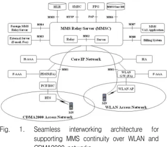
Fig. 1. Seamless interworking architecture for supporting MMS continuity over WLAN and CDMA2000 networks.
As illustrated in Fig. 1, we employed loosely-coupled approach and MIP approach with AAA to propose novel seamless interworking architecture for supporting MMS continuity over WLAN and CDMA2000 networks. It interfaces the Multimedia Messaging Service Center (MMSC) with many existing network elements such as the Short Messaging Service Center (SMSC), Push Proxy Gateway (PPG), Home Location Register (HLR), Home Agent (HA), AAA, Packet Data Service Node (PDSN), WLAN Gateway, WLAN Access Point (AP), and so on. It has two new functional entities specifically added to support the MIP which are the HA and the Foreign Agent (FA). The PDSN has been modified to act as the FA for CDMA2000 in addition to its original intended functionality. WLAN has been setup and connected through a local sub-network to the core network with its own gateway and the FA.
The AAA is used for authentication and
authorization of WLAN users as well as
CDMA2000 users. Unless it is firstly
authenticated by the AAA, no users can access the core network through CDMA2000 or WLAN.
The Mobile Node (MN) has been provided with the MIP client that supports both WLAN and CDMA2000.
MMS delivery between two MNs can be divided in two parts. In the first part, referred to Mobile Originated (MO) message delivery, the originator MN submits a new MMS message to the MMSC.
In the second part, after completely receiving the new MMS message from the originator MN, the MMSC delivers the new MMS message to the recipient MN. This part is referred to Mobile Terminated (MT) message delivery. The MN is identified with an Mobile Station International Subscriber Directory Number (MSISDN) in CDMA2000 and with an IP address in WLAN.
Currently in CDMA2000, with an MSISDN, the MMSC informs the recipient MN of the new MMS message through the SMS via the SMSC. In WLAN, however, there is no specific method to send the notification about the new MMS message to the recipient MN which is identified with an IP address, not an MSISDN.
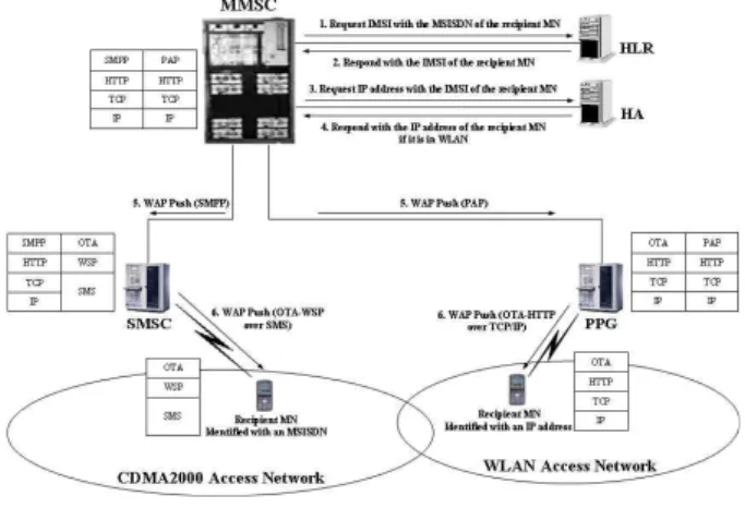
Fig. 2. Seamless notification architecture for supporting MMS continuity over WLAN and CDMA2000 networks.
The MMSC needs to find out an IP address of the recipient MN with the MSISDN provided by the originator MN before sending the notification
message about a new MMS message to the recipient MN in WLAN. As shown in Fig. 2, the MMSC first asks for the International Mobile Subscriber Identity (IMSI) to the HLR with the MSISDN. The MMSC requests an IP address of the recipient MN to the HA with the IMSI derived from the HLR. With the IP address, the MMSC sends the notification message by using the PAP to the PPG and then the PPG sends it to the recipient MN by using Push Over-the-Air (OTA) protocol. The MMSC originally creates the notification message. The PPG examines it and performs the required encoding and transformation. In the process, it generally should not remove any headers or the body of the message, although it may perform encoding or transforming. The PPG, however, may add additional headers to the notification message to enable the needed OTA services. The notification message is delivered using the Hypertext Transfer Protocol (HTTP) Post method, implying that the PPG acts as the HTTP client and the recipient MN acts as the HTTP server.
Ⅲ. Seamless Handover Architecture
Fig. 3. Seamless handover architecture for supporting MMS continuity over WLAN and CDMA2000 networks.
As shown in Fig. 3, we also provide practically
possible seamless handover architecture, such as an
initial MIP registration when an MN in CDMA2000 receives the notification message from the MMSC, an intra-network horizontal handover when the MN moves into another CDMA2000 while downloading the new MMS message, an inter-network vertical handover when the MN moves from CDMA2000 to WLAN while downloading the new MMS message, and an improved inter-network vertical handover.
3-1 Initial Mobile IP Registration
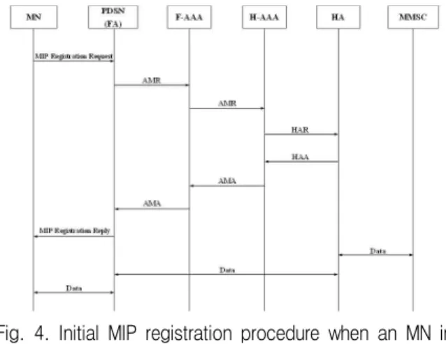
When an MN in CDMA2000 receives the notification message from the MMSC, we first consider an initial MIP registration to download the new MMS message. For simplicity, we suppose that the MN visits a foreign network. As illustrated in Fig. 4, the initial MIP registration can be decomposed in the following steps.
Fig. 4. Initial MIP registration procedure when an MN in CDMA2000 receives the notification message from the MMSC.
Step 1. The MN sends an MIP Registration Request message to the PDSN in order to download the new MMS message from the MMSC.
Step 2. The PDSN modifies the MIP Registration Request message into an AA-Mobile-Node-Request (AMR) message and sends it to the F-AAA.
Step 3. The F-AAA possibly adds or modifies some optional Attribute Value Pairs (AVPs) and forwards the AMR message to the H-AAA.
Step 4. The H-AAA generates a Home Agent
Request (HAR) message and sends it to the HA.
Step 5. The HA processes the HAR message and then responds with a Home Agent Answer (HAA) message to the H-AAA.
Step 6. After receiving the HAA message, the H-AAA generates an AA Mobile Node Answer (AMA) message and sends it to the F-AAA.
Step 7. The F-AAA possibly modifies the AMA message and forwards it to the PDSN.
Step 8. The PDSN ends the MIP Registration Reply message to the MN. Then, the MN can start downloading the new MMS message from the MMSC via the HA and the PDSN.
3-2 Intra-network Horizontal Handover
When the MN moves into another CDMA2000 while downloading the new MMS message, we consider an intra-network horizontal handover in the same administrative networks. As illustrated in Fig. 5, the intra-network horizontal handover between CDMA2000 access networks can be decomposed in the following steps.
Fig. 5. Intra-network horizontal handover procedure when the MN moves into another CDMA2000 while downloading the new MMS message.
Step 1. When the MN changes the point of
attachment between the old PDSN and the new
PDSN, it sends an MIP Registration Request message
to the new PDSN.
Step 2. The new PDSN modifies the MIP Registration Request message into an AMR message and sends it to the F-AAA.
Step 3. After receiving the AMR message, the F-AAA generates an AMA message and sends it to the new PDSN.
Step 4. The new PDSN sends the Binding Update message to the old PDSN to inform the old PDSN of the new CoA. We assume that there is already a Security Association (SA) between the new PDSN and the old PDSN in the same administrative network, so the Binding Update and Binding Acknowledgment messages are possible without additional authentication.
Step 5. The old PDSN replies with the Binding Acknowledgment message to confirm the update of binding cache entry on the MN. The old PDSN starts buffering the packets and retransmits them to the new PDSN.
Step 6. The new PDSN also sends the Binding Update message to the HA to inform the HA of the new CoA of the MN.
Step 7. The HA replies with the Binding Acknowledgment message to the new PDSN to confirm the update of binding cache entry on the MN.
Step 8. The new PDSN sends the MIP Registration Reply message to the MN. Then, the MN can still keep downloading the new MMS message from the MMSC via the HA and the new PDSN.
3-3 Inter-network Vertical Handover
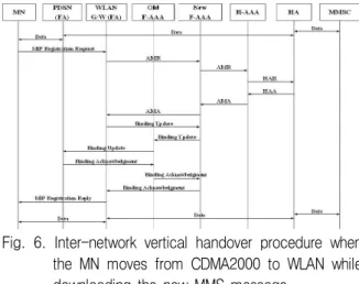
When the MN moves from CDMA2000 to WLAN while downloading the new MMS message, we consider an inter-network vertical handover in the different administrative networks. As illustrated in Fig. 6, the inter-network vertical handover between WLAN and CDMA2000 access networks can be decomposed in the following steps.
Fig. 6. Inter-network vertical handover procedure when the MN moves from CDMA2000 to WLAN while downloading the new MMS message.
Step 1. When the MN moves into WLAN, it sends an MIP Registration Request message to the WLAN Gateway.
Step 2. The WLAN Gateway modifies the MIP Registration Request message into an AMR message and sends it to the new F-AAA.
Step 3. The new F-AAA possibly adds or modifies some optional AVPs and forwards the AMR message to the H-AAA.
Step 4. The H-AAA generates a HAR message and sends it to the HA.
Step 5. The HA processes the HAR message and then responds with a HAA message to the H-AAA.
Step 6. After receiving the HAA message, the H-AAA generates an AMA message and sends it to the new F-AAA.
Step 7. The new F-AAA possibly modifies the AMA message and forwards it to the WLAN Gateway. In this case, the Binding Update and Binding Acknowledgment messages should be authenticated since these messages are performed in the different administrative networks. After the MN is authenticated, the WLAN Gateway starts signaling for the Binding Update.
Step 8. The WLAN Gateway sends the Binding
Update message to the new F-AAA to inform the
PDSN of the new CoA. The new F-AAA sends the
Binding Update message to the old F-AAA. Then,
the old F-AAA relays the Binding Update message to
the PDSN.
Step 9. The PDSN replies with the Binding Acknowledgment message to the old F-AAA to confirm the update of binding cache entry on the MN. The old F-AAA sends the Binding Acknowledgment message to the new F-AAA. Then, the new F-AAA relays the Binding Acknowledgment message to the WLAN Gateway. The PDSN starts buffering the packets and retransmits them to the WLAN Gateway.
Step 10. The WLAN Gateway sends the MIP Registration Reply message to the MN. Then, the MN can still keep downloading the new MMS message from the MMSC via the HA and the WLAN Gateway.
3-4 Improved Inter-network Vertical Handover
The inter-network vertical handover takes much longer time and larger traffic than the intra-network horizontal handover, which is likely to result in noticeable disruption in MMS service.
Therefore, we need to reduce the disruption time during the inter-network vertical handover. The key idea is that the SA between the MN and the F-AAA in neighboring networksis established before the actual handover occurs. Thus, when an MN hands off to a neighboring network, the registration request is processed locally within that network without going all the way to the H-AAA.
The pre-establishment of the SA can be performed in two fashions. One is a distributed fashion where the new F-AAA directly contacts the neighboring F-AAAs. The other is that the new F-AAA informs the H-AAA of the neighboring F-AAAs and lets the H-AAA contact them. We believe that the neighboring F-AAAs are not necessarily cooperative among each other.
Since the new F-AAA is unlikely to know which neighboring networks are available to the MN, we
assume that the H-AAA will send the messages for Shadow Registration only to the relevant neighboring F-AAAs.
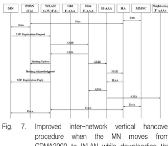
As illustrated in Fig. 7, the improved inter-network vertical handover between WLAN and CDMA2000 access networks can be decomposed in the following steps.
Fig. 7. Improved inter-network vertical handover procedure when the MN moves from CDMA2000 to WLAN while downloading the new MMS message.
Step 1. When the MN moves into WLAN, it sends an MIP Registration Request message to the WLAN Gateway.
Step 2. The WLAN Gateway modifies the MIP Registration Request message into an AMR message and sends it to the new F-AAA.
Step 3. Since the SA between the MN and the new F-AAA in the neighboring network is already established according to Shadow Registration, the new F-AAA generates an AMA message and sends it to the WLAN Gateway.
Step 4. The WLAN Gateway sends the Binding Update message to the PDSN to inform the new CoA.
Step 5. The PDSN replies with the Binding
Acknowledgment message to the WLAN Gateway to
confirm the update of binding cache entry on the
MN. The PDSN starts buffering the packets and
retransmits them to the WLAN Gateway.
Step 6. At the same time, the new F-AAA possibly also adds or modifies some optional AVPs to the AMR message and forwards it to the H-AAA.
Step 7. The H-AAA generates a HAR message and sends it to the HA.
Step 8. The HA processes the HAR message and then responds with a HAA message to the H-AAA.
Step 9. After receiving the HAA message, the H-AAA generates an AMA message and sends it to both the new F-AAA and only to the relevant neighboring F-AAAs for Shadow Registration.
Step 10. The WLAN Gateway sends the MIP Registration Reply message to the MN. Then, the MN can still keep downloading the new MMS message from the MMSC via the HA and the WLAN Gateway.
Ⅳ. Simulation Results
Through the Network Simulator 2 (NS-2), we evaluate the intra-network horizontal handover, the inter-network vertical handover, and the improved inter-network vertical handover. We assume that the processing time in each entity is negligible since it normally takes less than 1ms [9].
100 125 150 175 200 225 250 275 300
0 20000 40000 60000 80000 100000 120000 140000
Intra-network Horizontal Handover Inter-network Vertical Handover
Throughput (# of packet)
Time (sec)
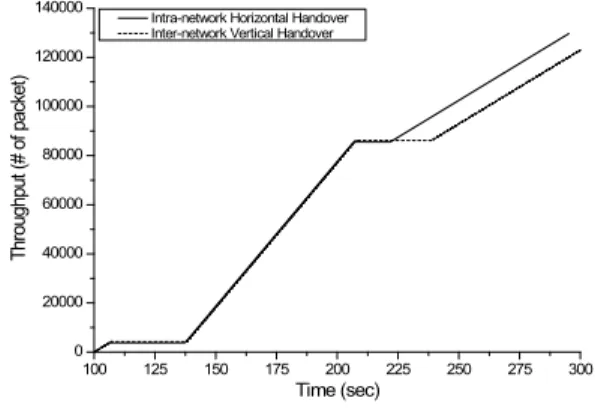
Fig. 8. Throughput of intra-network horizontal handover and inter-network vertical handover.
100 125 150 175 200 225 250 275 300
0 20000 40000 60000 80000 100000 120000 140000
Inter-network Vertical Handover Improved Inter-network Vertical Handover
Throughput (# of packet)
Time (sec)
Fig. 9. Throughput of inter-network vertical handover and improved inter-network vertical handover.
We show the throughput in Fig. 8 and Fig. 9.
Compared to the intra-network horizontal handover, the inter-network vertical handover needs the Binding Update/Acknowledgment messages between the WLAN Gateway and the new F-AAA, the Binding Update/
Acknowledgment messages between the old
F-AAA to the new F-AAA, the Binding
Update/Acknowledgment messages between the
old F-AAA and the PDSN, the AMR/AMA
messages between the new F-AAA and the
H-AAA, and the HAR/HAA messages between
the H-AAA and the HA. Therefore, the
throughput of the inter-network vertical handover
is lower than that of the intra-network horizontal
handover. However, the improved inter-network
vertical handover can enhance the throughput
since the SA between the MN and the new
F-AAA is already established according to
Shadow Registration. We can improve the
throughput by the average 7.78% and the
maximum 11.12%.
0 30 60 90 120 150 180 210 240 270 300 0
10 20 30 40 50 60 70 80
90 Intra-network Horizontal Handover Inter-network Vertical Handover
Drop (# of packet)
Time (sec)
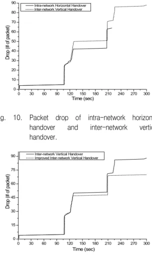
Fig. 10. Packet drop of intra-network horizontal handover and inter-network vertical handover.
0 30 60 90 120 150 180 210 240 270 300
0 15 30 45 60 75
90 Inter-network Vertical Handover Improved Inter-network Vertical Handover
Drop (# of packet)
Time (sec)
Fig. 11. Packet drop of inter-network vertical handover and improved inter-network vertical handover.
We show the packet drop in Fig. 10 and Fig. 11.
Due to the additional smooth handover and AAA procedures, the packet drop of the inter-network vertical handover is larger than that of the intra-network horizontal handover. However, the improved inter-network vertical handover can enhance the packet drop since it reduces the time to process the Binding Update/ Acknowledgment messages between the WLAN Gateway and the new F-AAA, the Binding Update/
Acknowledgment messages between the old F-AAA to the new F-AAA, the Binding Update/Acknowledgment messages between the old F-AAA and the PDSN. We can improve the packet drop by the average 14.31% and the maximum 20.45%.
100 125 150 175 200 225 250 275 300
0 2 4 6 8 10 12 14 16
Intra-network Horizontal Handover Inter-network Vertical Handover
Delay (sec)
Time (sec)
Fig. 12. Transmission delay of intra-network horizontal handover and inter-network vertical handover.
100 125 150 175 200 225 250 275 300
0 2 4 6 8 10 12 14 16
Inter-network Vertical Handover Improved Inter-network Vertical Handover
Delay (sec)
Time (sec)
Fig. 13. Transmission delay of inter-network vertical handover and improved inter-network vertical handover.
We show the transmission delay in Fig. 12 and
Fig. 13. Compared to the intra-network horizontal
handover, the inter-network vertical handover
needs the additional smooth handover and AAA
procedures due to the Binding
Update/Acknowledgment messages between the
WLAN Gateway and the new F-AAA, the Binding
Update/Acknowledgment messages between the
old F-AAA to the new F-AAA, the Binding
Update/ Acknowledgment messages between the
old F-AAA and the PDSN, the AMR/AMA
messages between the new F-AAA and the
H-AAA, and the HAR/HAA messages between
the H-AAA and the HA. Therefore, the
inter-network vertical handover needs longer
transmission delay than the intra-network
horizontal handover does. However, the improved inter-network vertical handover can enhance the transmission delay since it reduces the time to process the additional procedures during the inter-network vertical handover. We can improve the transmission delay by the average 33.84% and the maximum 48.35%.
Ⅴ. Conclusions
This paper designed novel seamless interworking architecture for supporting MMS continuity over WLAN and CDMA2000 networks by reusing the existing standards and network elements at the same time. This paper also presented seamless notification architecture and seamless handover architecture that couldn't be possible within current MMS reference architecture. This paper will make a contribution for service providers to offer their customers with seamless MMS service over WLAN and CDMA2000 networks. For secure MMS service, we need more investigations in the area of common authentication and mobility management.
Acknowledgments
This research was supported by the Internet Information Retrieval Research Center (IRC) in Hankuk Aviation University. IRC is a Regional Research Center of Gyeonggi Province, designated by ITEP and Ministry of Commerce, Industry and Energy.
References
[1] A. K. Salkintzis, C. Fors, and R. Pazhyannur,
"WLAN-GPRS integration for next-generation mobile data networks,"
IEEE Wireless Communications,pp. 112-124, Oct. 2002.
[2] A. K. Salkintzis, "Interworking techniques and architectures for WLAN/3G integration towar d 4G mobile data networks,"
IEEE Wireless Communications, pp. 50-61, June 2004.
[3] S. H. Wang and P. Y. Kong, "A novel vertical handover scheme for integrated WLAN and cellular wireless networks,"
ICCS 2004, pp. 526-530.
2004.
[4] ETSI TR 101 957, "Broadband radio access networks (BRAN), HIPERLAN type 2: Requir ements and architectures for interworking bet ween HIPERLAN/2 and 3rd generation cellular systems," June. 2001.
[5] K. Ahmavaara, H. Haverinen, and R. Pichna,
"Interworking architecture between 3GPP and WLAN systems,"
IEEE Communications Magazine, pp. 74-81, Nov. 2003.
[6] C. Perkins, "IP mobility support," IETF RFC 2002, Oct. 1996.
[7] C. Perkins, "Route optimization in Mobile IP,"
Internet Draft, Sep. 2001.
[8] C. Perkins, "Mobile IP joins forces with AAA,"
IEEE Personal Communication
, Aug. 2000.
[9] C. Perkins and K. Y. Wang, "Optimized smooth handoffs in Mobile IP,"
IEEE International Symposium on Communication, pp. 340-346, Jul. 1999.
김 수 용 (金洙龍)
1997년 2월 : 한국항공대학교 항공 통신정보공학과(공학사)
1999년 2월 : 한국항공대학교 항공 통신정보공학과(공학석사) 2006년 8월 : 한국항공대학교 정보
통신공학과(공학박사)
1999년 3월~2000년 3월 : (주)라 딕스 DECT 단말기 소프트웨어(주임연구원)
2000년 3월~현재 : (주)모토로라 코리아 휴대폰 단말 기 소프트웨어(선임연구원)
관심분야 : 모바일 프로그래밍, 차세대 무선인터넷, 멀 티미디어 서비스
조 성 준 (趙成俊)
1969년 2월 : 한국항공대학교 항 공통신공학과(공학사)
1975년 2월 : 한양대학교 대학원 (공학석사)
1981년 3월 : 오사카대학 대학원 (공학박사)
1972년 8월~현재 : 한국항공대학 교 항공전자 및 정보통신공학부 교수
관심분야 : 이동통신, 무선통신, 환경전자공학, 이동무 선인터넷