Introduction
Rotating flows in annular passages with rotation of the inner cylinder are important and have application in bearings, rotating tube heat exchangers, and drilling of oil wells where mud flows between the drill shaft
and the well casing to remove cuttings.
To transfer drilling method to the oil field and keeping high rotational speed and small annulus, many problems occur due to the sedimentary type of formations drilled, and hydraulics become crucial.
It is well known that the stability of a viscous flow in the small annular gap between concentric rotating cylinders was first considered experimentally and theoretically by Taylor (1923). He found that, when the inner cylinder is at rest while the outer cylinder is rotating, the flow is stable. Conversely, when the outer cylinder is at rest, the flow is unstable.
Literature reviews revealed that only several papers
Vortex Flow Study on the Non-Newtonian Fluids in Concentric Annulus with Rotating Inner Shaft
Young Ju Kim
1)*, Chi Ho Yoon
1), Nam Sub Woo
2), Young Kyu Hwang
2), Yong Chan Park
1), Jong Myung Park
1)and Seok Ki Kwon
1)안쪽축이 회전하는 동심환형관내 비뉴튼유체의 Vortex 유동연구
김영주* · 윤치호 · 우남섭 · 황영규 · 박용찬 · 박종명 · 권석기
Abstract :The paper concerns the characteristics of transitional flow of non-Newtonian fluids in a concentric annulus with a diameter ratio of 0.52, whose outer cylinder is stationary while inner one is rotating. The pressure losses and skin friction coefficients have been measured for the fully developed flows of 0.2% aqueous solution of sodium carboxymethyl cellulose (CMC) at inner cylinder rotational speed of 0~600 rpm. The transitional flow has been examined by the measurement of pressure losses and visualization of flow fields to reveal the relationship between the Reynolds and Rossby numbers in relation to the skin friction coefficients and to understand the flow instability mechanism. The occurrence of transition has been checked by the gradient change of pressure losses and skin-friction coefficients with respect to the Reynolds numbers. Consequently, the critical Reynolds number decreases as the rotational speed increases. Thus the rotation of inner cylinder promotes the onset of transition due to the excitation of Taylor vortices.
Key words :Vortex flow, Concentric annulus, Rotating flow, Skin-friction coefficient
요 약: 본 논문은 안쪽 실린더가 회전하고 바깥쪽 실린더가 고정된 반경비가0.52인 동심환형관내 비뉴튼유체
의 천이유동 특성을 관찰했다 안쪽실린더가. 0~600 rpm으로 회전하고0.2% CMC수용액을 완전히 발달된 유동
에서 압력강하와 표면마찰계수를 측정하였다 천이유동은 표면마찰계수에 대한 레이놀즈수와 로스비수 관계.
및 유동의 불안정성 메카니즘을 나타내기 위해 압력강하를 측정하였다 천이의 발생은 레이놀즈수에 관해 압력.
손실과 표면마찰계수의 구배변화에 의해 조사했다 결과적으로 임계레이놀즈수는 회전속도가 증가함에 따라.
감소함을 알 수 있다 따라서 안쪽실린더의 회전은. Taylor 와류의 자극 때문에 천이의 시작을 촉진시킨다. 주요어 :와유동 동심환형관 회전유동 표면마찰계수, , ,
년 월 일 접수 년 월 일 채택
2007 6 5 , 2007 10 19
1)韓國地質資源硏究院 지반안전연구부
성균관대학교 기계공학부 2)
*Corresponding Author(金英周) E-mail; [email protected]
Address; Korea Institute of Geoscience and Mineral Resources
연구논문
are reported for the numerical study on the rheological properties of drilling fluids in concentric and eccentric annuli because of the difficulties of experiment study.
Diprima (1960) and Stuart (1958) investigated the relationship between Taylor number and stability by applying the nonlinear theory. It was found that the flow is relatively stable when outer cylinder is rotating, and thus the critical (axial-flow) Reynolds number Rec
is larger and pressure loss is smaller than when inner cylinder is rotating (Yamada, 1962; Yamada et al, 1969; Yamada and Watanabe, 1973). Nakabayashi et al. (1974), Nouri et al. (1993), and Nouri and Whitelaw (1994) found that the Rec decreases as the rotating Reynolds number (Rew) and the ratio of eccentricity increase.
Recently, Escudier et al. (2002) carried out numerical and experimental study of fully developed laminar flow of a Newtonian liquid through an eccentric annulus.
The results are reported for calculations of the flowfield, wall shear stress and friction factor for the values of eccentricity and Taylor number.
Two main different techniques are used in drilling.
Conventional drilling in sedimentary formations uses small diameter rods rotating at a low speed inside a large hole (the pipe/hole diameters ratio is about 0.30).
This conventional technique is largely experienced all around the world and empirical rules are deduced to help drilling designers. Mining drilling (through hard formations) consists of small diameter rods rotating at a high speed but inside a hole with nearly the same dimensions (the rod/hole diameters ratio is about 0.9) by Delwiche et al. (1992).
In this study, we measured the pressure loss and the skin friction coefficient of the flow through an annulus, with the inner cylinder rotating and the outer one stationary, under fully developed condition, using 0.2%
aqueous solution of sodium carboxymethyl cellulose (CMC). The range of the rotational speed of the inner cylinder is 0~600 rpm which corresponds to the range of 100 ≤ Re ≤ 23,000.
Data Reduction
The equation of the average axial velocity in a concentric annulus without rotating, expressed in terms
of the pressure loss dp/dz, becomes Eq. (1)
)) / 1 ln(
1 1 (1 )8
( 2 24 2
η η η η µ
− −
−
⋅ −
= o
z R
dz
v dp (1)
where (η= Ri/Ro) is the ratio of radius and μ is viscosity. Also, the skin friction coefficient Cf can be expressed as
z
f v
Dh dz C dp
2ρ 2
⋅
= (2)
where Dh(=2(Ro-Ri)) is the hydraulic diameter and ρ is density of fluid. Eqs. (1) and (2) are combined as:
2 2 2 4
) 1 ( )) / 1 ln(
1 1 (1
16 η
η η η
η − − −
−
= − e
Cf R (3)
where Re is the Reynolds number.
In the above Eq. (3), the following constants are used:
Dh= 18.4×10⁻³ m, Ro= 19.0×10⁻³ m, Ri= 10.0×10⁻³ m, η= 0.52.
In the case of a concentric annulus, Cf is given by
Re 8 .
=23
Cf (4)
In the experiment, the pressure losses were measured by
z h g dz
dp ccl
∆
= sinθ (ρ 4−ρ)
(5)
whereρcclis density of ccl4. The experimental value of skin friction coefficients can be evaluated by sub- stituting Eq. (5) into Eq. (2).
Experimental Apparatus
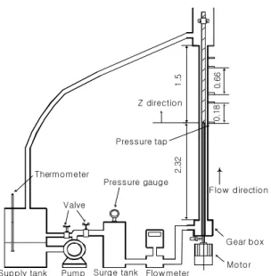
The experimental equipments consist of a cylinder part, supporting part, fluid-providing and rotating parts
and measuring part which measures the flow rate, pressure loss and the temperature as shown in Fig. 1.
A centrifugal pump delivered the working fluid from a supply tank through a surge tank that located in im- mediately after the pump outlet act to remove pulsation in the flow prior to entry into the test section. The fluid flowed into the annular passage with an outer brass pipe of nominal inside diameter, Ro, of 19 mm and 3.82 m long and an inner stainless steel rod of diameters, Ri, of 10 mm and 17 mm. To insure fully developed flow in the measuring section, the length of the straight pipe downstream of the test section was 2.32 m, corresponding to 116 hydraulic diameters, with a uniform step at the inlet in order to produce an artificially thickened boundary layer. The rotating cylinder with the length of 1.5 m and the non-rotating counter part are connected by bronze bearings in order to prevent vibration and eccentricity caused by three parts of the outer cylinder.
Static pressures were measured with holes of 0.5 mm diameter distributed longitudinally in the outer cylinder.
The static pressures were read from a calibrated ma- nometer with 1mm resolution. The specific gravity of the manometer fluid ccl4 was 1.88 giving a height range of 20~600 mm.
The effective viscosities used in the calculation of effective Reynolds number were obtained by deter- mining the average wall shear stress from pressure measurements and the dividing by the shear rate deter- mined from the power law relationship for 0.2% CMC solutions. The effective viscosity of 0.2% CMC solution for the same flow rate of 6 LPM becomes 18 cP at 0 rpm and 22 cP at 400 rpm. The maximum uncertainties were less than ±6 and ±3% for the turbulent flow of water and of 0.4% CMC solution, respectively. In practice, the inner cylinder is slightly distorted, and it has proved impossible to achieve a concentric geometry over the entire length of the test section. The cylinder and the rotating part have been supported by a construction H-beam of 4 m long steel (SK40).
The flow rate has been measured with a magnetic flow meter whose accuracy is within the limit of 0.5%.
The temperature of the working fluid has been measured with a digital multi-meter. And the inner cylinder may be rotated at any speed up to a maximum of 1500 rpm by means of a A. C. motor and gear box.
Results And Discussion
Pressure Loss and Flow Characteristics
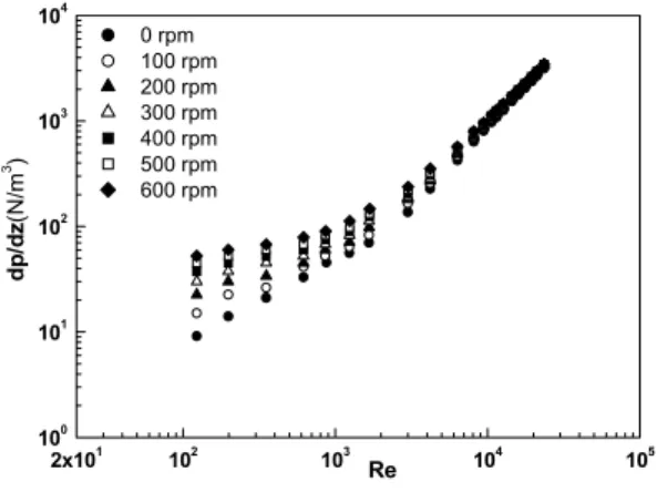
The skin friction coefficients as a function of Re for 0~600 rpm are shown in Fig. 2. For water, the pressure loss is difficult to measure because it is small in the laminar regime of low Reynolds number. However, the viscosity of 0.2% aqueous solution of CMC is about six times larger than that of water, and it is relatively easy to measure the pressure loss. Thus, the experiment was also performed in 0.2% aqueous solution of CMC within the range of 100 ≤ Re ≤ 23,000. Figure 3 illustrates the skin friction coefficients of 0.2% aqueous solution of CMC.
The occurrence of transition has been checked by the gradient change of pressure losses and skin-friction coefficient with respect to the Reynolds numbers.
The critical Reynolds number, Rec of the 0.2%
aqueous solution of CMC decreases as rotational speed increases, as shown in Figs. 2 and 3. On the other hand, Rec increases as Ro increases, that is, the
Z direction 0.180.66 Pressure tap
Supply tank Pump Surge tank Flowmeter Valve
Pressure gauge Thermometer
Flow direction
Motor Gear box
1.52.32
Fig. 1. Schematic diagram of experimental apparatus. (All dimensions are in meter)
rotational Reynolds number Rew decreases.
The laminar regime considered here was confined to the case of Re < Rec. The Rec decreases according to the increase of the rotational speed.
To investigate the effect of rotation on the pressure loss, we considered the Rossby number, Ro which is defined as Ro= .
If the data of Fig. 3 for 0.2% aqueous solution of CMC are reordered the average value of Cf* in the laminar regime increases by 21~52% as the rotational speed increases by 100~600 rpm. Figure 4 allows comparison of the skin friction coefficients for New- tonian and non-Newtonian fluids for all eccentricities.
In turbulent flow of the Newtonian fluid, Fig. 4(a), the results are as expected with Cf higher for an eccen- tricity of 0 than for 0.5 and 1.0 by 8% and 22%
respectively. With the 0.2% CMC, figure 4(b), this monotonic pattern no longer exists and the values of Cf with 0 eccentricity are much higher than with an eccentricity of 1 and smaller than with an eccentricity of 0.5, particularly in the range of 105 < Re < 2,000. A possible explanation is that the flow is not fully developed, suggesting a longer hydrodynamics entry length as proposed by Shah & London (1978).
The entry length of the present arrangement (116Dh) is more than sufficient to produce fully developed laminar flow in a concentric annulus, but it will produce fully developed laminar flow in the eccentric annulus only for Re below 500.
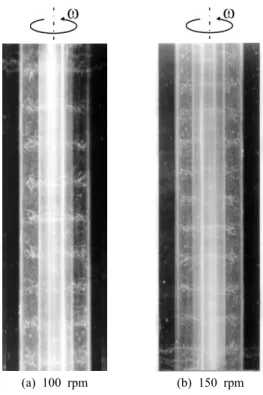
Flow Visualization
Figure 5 shows the experimental visualization of the flow field of water when the inner cylinder rotates at 100 rpm and 150 rpm for Re = 0 respectively. When the flow rate is zero, the Taylor vortex does not occur at 0~40 rpm because the effect of rotation is small, but it occurs at 50~130 rpm. At 100 rpm, the wavelength λ, which is defined as the length of a pair of the Taylor vortex, is 20.1 mm. When the rotational speed in- creases up to 150~170 rpm, the wavelength becomes too small to measure it. When the rotational speed increases up to 180~200 rpm, the regular Taylor vortex can not be observed. And the wavelength becomes too small to be measured it.
2x101 102 103 104 105
100 101 102 103 104
dp/dz(N/m3 )
Re 0 rpm
100 rpm 200 rpm 300 rpm 400 rpm 500 rpm 600 rpm
2x101 102 103 104 105
10-3 10-2 10-1 100 5x100
Cf=0.0014+0.21/Re0.32 Cf=23.8/Re
Cf
Re
0 rpm 100 rpm 200 rpm 300 rpm 400 rpm 500 rpm 600 rpm
Fig. 2. Pressure loss of 0.2% CMC water solution as a function of Re for 0 ≤ N ≤ 600 rpm.
Fig. 3. Skin friction coefficient of 0.2% CMC water as a function of Re for 0 ≤ N ≤ 600 rpm.
2x101 102 103 104 105
10-3 10-2 10-1 100
e=0 e=0.5 e=1
(b) Cf (a)
Re e=0 e=0.5 e=1
Fig. 4. Skin friction coefficient as a function of Re.
(a) Newtonian fluid (b) non-Newtonian fluid
These phenomena mean that the Taylor vortex develops from laminar to turbulent flow as the rotational speed increases when the axial flow does not exist. If the clearance between the inner and outer cylinders is small, the wavelength can be predicted by the following equation, which was theoretically suggested by Prandtl (1993),
λ= Ri(116.8/Rw)2/3 (6)
Equation (6) expresses the change of the wavelength with respect to the change of the rotational speed. As the rotational speed increases from 100 rpm to 150 rpm, the wavelength, λ, obtained by the theoretical Eq.
(6) is decreased by 23% and that measured by the flow visualization is decreased by 17.3% approximately.
This shows that the theoretical Eq. (6) may be only available in the range ofη> 0.8 since the experimental results show the ηof 0.52. From this, the wavelength is much influenced by the rotation as the distance between concentric cylinders becomes small. Vortex does not occur at Re = 400 corresponding to the ro-
tational speed of 80 rpm, and there exists only the spiral flow because the rotation effect is small. At 100 rpm, the vortex can be observed. From these results, it is seen spiral flow because the rotation effect is small.
At 100 rpm, the vortex can be observed. From these results, it is seen that the specific Reynolds number, which discern laminar Taylor vortex regime with other flow regime, exists.
For example, in the case of Re = 400 and 100 rpm, the wavelength is 28.15 mm which is longer than that for the case without axial flow. At 150~200 rpm, its form is similar to the case without axial flow, and the distance between a pair of vortex is as short as 26.92 mm.
If the axial flow exists, it is difficult to compare the wavelength and because we could not acquire enough data with the change of rotational speed. But, it was confirmed that the wavelength decreases as the rota- tional speed increases.
Conclusions
In this study, the effects of rotational speeds, flow rates, and working fluids on pressure losses and skin friction coefficients in a helical flow field have been experimentally investigated.
The pressure loss increases as the rotational speed increases, but the gradient of pressure loss decreases as Re increases in regime of transition and turbulence.
The value of Rec decreases as the rotational speed increases and Ro decreases.
Also, the increase in flow disturbance caused by Taylor vortex in a concentric annulus with rotating inner cylinder results in the decrease in Rec with the increase in Cf. The effect of rotation on pressure loss is relatively small in turbulent regime.
The distinct Taylor vortex was observed at 50~130 rpm for the zero flow rate. When the axial flow exists, the Taylor vortex was observed at Re = 400 and 100 rpm. Also, it was shown that the wavelength decreases as the rotational speed increases and that the Taylor vortex has a significant effect on the flow field as the Reynolds number decreases. Skin friction coefficients decrease as the eccentricity increases.
(a) 100 rpm (b) 150 rpm
Fig. 5. Taylor vortices with the inner cylinder rotating.
(Re = 0).
Nomenclature
Cf skin friction coefficients Dh hydraulic diameter, 2(Ro - Ri) dp/dz pressure loss (N/m3)
e displacement of inner cylinder axis from outer cylinder axis
Ri radius of inner cylinder (mm) Ro radius of outer cylinder (mm) Re Reynolds number,
Rec critical Reynolds number
Rew rotational Reynolds number, ωR1(R2-R1)/ν Ro Rossby number, 2/ Rω 1
average velocity in z-direction (m/s)
∆z distance between pressure taps (mm) (Greek Symbols)
η ratio of radius, R1/R2
μ absolute viscosity (Pa s)・ ν kinematic viscosity (m2/s) ρ density of fluid (kg/m3)
ω angular velocity of inner cylinder (rad/s)
Acknowledgements
The authors express appreciation to the Ministry of Maritime Affairs and Fisheries (MOMAF) of Korea for their full support in this study.
References
Bird, R. B., Stewart, W. E. and Lightfoot, E. N., 1962, Transport Phenomena, pp. 34-70.
Delwiche, R. A., Stratabit, D. B. and Lejeune, M. W. D., 1992, “Slimhole Drilling Hydraulics,” Society of Petroleum Engineers Inc., SPE 24596, 67th Annual Technical Con-
ference, pp. 521-541.
Diprima, R. C., 1960, “The Stability of a Viscous Fluid Between Rotating Cylinders with an Axial Flow,” Journal of Fluid Mechanics, Vol. 366, pp. 621-631.
Escudier, M. P., Gouldson, I. W, Oliveira, P. J. and Pinho, F. T., 2002, “International Journal of Heat and Fluid Flow,” Vol. 21, pp. 92-103.
Nakabayashi, K., Yamada, Y. and Seo, K., 1974, “Rota- tional and Axial through the Gap between Eccentric Cylinders of which the Outer One Rotates,” Bull. JSME, Vol. 17, No. 114, pp. 1564-1571.
Nouri, J. M., Umur, H. and Whitelaw, J. H., 1993, “Flow of Newtonian and Non-Newtonian Fluids in Concentric and Eccentric Annuli,” Journal of Fluid Mechanics, Vol.
253, pp. 617-641.
Nouri, J. M. and Whitelaw, J. H., 1994, “Flow of New- tonian and Non-Newtonian Fluids in a Concentric Annulus With Rotation of the Inner Cylinder,” Journal of Fluids Engineers, Vol. 116, pp. 821-827.
Ogawa, A., 1993, Vortex Flow, CRC Press Inc., pp. 169- 192.
Shah, R. K. and London, A. L., 1978, “Laminar flow forced convection in ducts,” Academic.
Stuart, J. T., 1958, “On the Nonlinear Mechanics of Hydro- dynamic Stability,” Journal of Fluid Mechanics, Vol. 4, pp. 1-21.
Taylor, G. I., 1923, “Stability of a Viscous Fluid Contained Between Two Rotating Cylinders,” Phil. Trans. A, Vol.
223, pp. 289-343.
Yamada, Y., 1962, “Resistance of a Flow through an An- nulus with an Inner Rotating Cylinder,” Bull. JSME, Vol.
5, No. 18, pp. 302-310.
Yamada, Y., Nakabayashi, K. and Maeda, K., 1969, “Pres- sure Drop of the Flow through Eccentric Cylinder with Rotating Inner Cylinders,” Bull. JSME, Vol. 12, No. 53, pp. 1032-1040.
Yamada, Y. and Watanabe, S., 1973, “Frictional Moment and Pressure Drop of the Flow through Co-Axial Cylinders with an Outer Rotating Cylinder,” Bull. JSME, Vol. 16, No. 93, pp. 551-559.
김 영 주 윤 치 호
현재 한국지질자원연구원 지반안전연구부 선임연구원 (本 學會誌 第 卷 第 号 參照43 4 )
현재 한국지질자원연구원 지반안전연구부 책임연구원 (本 學會誌 第 卷 第 号 參照43 2 )
우 남 섭(禹南燮) 황 영 규(黃英奎)
년 월 성균관대학교 기계공학과 1997 2
공학사
년 월 성균관대학교 기계공학과 1999 2
공학석사
년 월 성균관대학교 기계공학과 2007 8
공학박사
B.S.E, Mechanical Engineering, Sung- kyunkwan University, Republic of Korea, 1977
M.S.E, Mechanical Engineering, Uni- versity of Wisconsin at Madison, U.S.A., 1981
Ph.D., Mechanical Engineering, State University of NewYork at Buffalo, U.S.A., 1984
년 현재 성균관대학교 기계공학부 1984 ~
교수 현재 성균관대학교 기계공학부 기계기술연구원
(E-mail; [email protected])
현재 성균관대학교 기계공학부 교수 (E-mail; [email protected])
박 용 찬 박 종 명
현재 한국지질자원연구원 지반안전연구부 선임연구원 (本 學會誌 第 卷 第 号 參照43 4 )
현재 한국지질자원연구원 지반안전연구부 선임연구원 (本 學會誌 第 卷 第 号 參照44 4 )
권 석 기
현재 한국지질자원연구원 지질박물관 선임연구원 (本 學會誌 第 卷 第 号 參照43 4 )