* 경북대학교 일반대학원 기계공학과
+ 교신저자, 경북대학교 기계공학부 ([email protected]) 주소: 702-701 대구광역시 북구 대학로 80
5축 공작기계에서 회전 테이블의 반경 오차 성능 평가
이광일*, 양승한+
(논문접수일 2012. 03. 15, 수정일 2012. 03. 29, 심사완료일 2012. 03. 30)
Performance Evaluation of Radial Error of a Rotary Table at Five-axis Machine Tool
Kwang-Il Lee*, Seung-Han Yang+
Abstract
In this paper, the radial error of a rotary table at five-axis machine tool is evaluated by utilizing ISO 230-2 and estimation method using double ball-bar. The geometric error of a rotary table is defined as position dependent geometric errors or position independent geometric errors according to their physical character. Then estimation method of geometric errors using double ball-bar is simply summarized including measurement path, parametric modeling and least squares approach.
To estimate representative radial error, offset error, set-up error which affect to the double ball-bar data, mean value of measured data including CCW/CW-direction are used at estimation process. Radial errors are separated from measured data and used for evaluation with ISO 230-2. Finally, suggested evaluation method is applied to a rotary table at five-axis machine tool and its result is analyzed to improve the accuracy of the rotary table.
Key Words : Five-axis machine tool(5축 공작기계), Rotary table(회전 테이블), Geometric error(기하학적 오차), Radial error(반경 오차), Offset error(옵셋 오차), Set-up error(셋업 오차), Double ball-bar(볼바)
1. 서 론
5축 공작기계는 공구와 공작물 사이의 상대 위치 및 방향의 제어가 용이하며 복잡한 형상의 제품을 정확하게 가공하기 위 해 산업 현장에서 널리 사용한다. 이러한 5축 공작기계는 일반 적으로 3개의 직선 이송축과 2개의 회전 테이블로 구성한다
(1~3)
. 그러나 제어하여야 하는 이송축의 증가는 end-effector의 위치 정확도에 영향을 미치는 오차 개수의 증가를 필연적으로 야기한다(4). 위치 정확도에 영향을 미치는 주요 오차에는 준정 적 오차인 기하학적 오차, 열 변형 오차 및 동적 오차가 있다.
특히 기하학적 오차는 위치 정확도에 영향을 미치는 여러 오차
중 가장 큰 부분을 나타낸다(5~7). 직선 이송축의 기하학적 오차 측정에는 레이저 간섭계, 정전용량 센서와 스트레이트 에지 및 볼바를 사용하며 다양한 측정 및 평가 방법이 개발되었다(8~13). 그러나 회전 테이블의 기하학적 오차 측정과 관련한 연구 및 평가 방법은 미흡하다(14~17).
본 논문에서는 회전 테이블의 기하학적 오차 중 반경 오차의 평가를 위하여 ISO 230-2를 기반으로 하는 방법을 제안하고(18), 5축 공작기계의 회전 테이블에 적용한다. 여기서 반경 오차는 볼바를 사용한 방법을 이용하여 추정한다(19).
2장에서는 회전 테이블의 기하학적 오차 요약 및 볼바를 사 용한 회전 테이블의 반경 오차를 추정하는 방법을 정리한다.
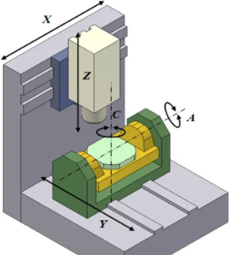
Fig. 1 Configuration of 5-axis machine tool
Fig. 2 Geometric errors of a rotary table
3장에서는 ISO 230-2를 기반으로 하여 회전 테이블의 반경 오 차를 평가하는 방법을 제안하고 이를 활용하여 5축 공작기계의 회전 테이블의 반경 오차를 평가한다. 최종적으로 4장에서는 본 논문을 정리 및 요약하여 결론을 나타낸다.
2. 회전 테이블의 반경 오차 추정
본 논문에서 모델링 및 실험에 사용한 5축 공작기계는 Fig. 1 과 같으며, 틸팅-회전 테이블 TTTRR의 구조를 가진다.
2.1 회전 테이블의 기하학적 오차
회전 테이블 C의 기하학적 오차는 ISO 230-7에 나타낸 바와 같이 회전 테이블 자체의 오차와 회전 테이블과 다른 축 사이의 오차로 정의하며 Fig. 2와 같다. 여기서 회전 테이블 자체의 오 차 δic, εic(i=x,y,z)는 지령값 c(rad)에 따라서 변동하는 위치 종 속적인 오차(position dependent geometric errors)이며, 회전 테이블과 다른 축 사이의 오차 oic, sic(i=x,y)는 지령값 c(rad)와
는 무관하며 위치 독립적인 오차(position independent geometric errors)이다. 직선 이송축 Y의 좌표계 {Y}에서 정의하는 회전 테이블 C의 좌표계 {C}는 기하학적 오차 및 동차 변환 행렬 (homogeneous transform matrix)을 사용하여 식 (1)과 같이 계 산한다.
(1)
여기서,
,
,
,
cos sin
sin cos
를 나타낸다.
2.2 볼바를 사용한 반경 오차 추정
볼바를 사용하여 회전 테이블 C의 반경 오차 δxc, δyc를 추정 하기 위한 볼바의 측정 방법은 Fig. 3에 나타낸 바와 같이 측정 하고자 하는 오차에 대한 볼바의 측정 민감도를 고려하여 2번 의 측정을 필요로 한다. 측정 순서는 좌표계 {C}의 중심에 볼바 의 첫 번째 볼(workpiece ball; WB)을 고정하고 직선 이송축 X를 사용하여 볼바의 기준 길이 R의 위치에 볼바의 두 번째 볼(tool ball; TB)을 위치한다. 그리고 볼바의 측정 데이터 R+
ΔR1는 회전 테이블 C를 정적 이송하면서 획득한다. 이 후 직선 이송축 X, Y를 사용하여 원호 이송함으로써 TB를 직선 이송축 Y의 방향에 위치하고 앞서의 경우와 같이 정적인 측정을 통하 여 측정 데이터 R+ΔR2를 획득한다. 직선 이송축 X, Y를 사용 하여 원호 이송을 진행하는 것은 2번의 측정에서 동일한 셋업 오차 (wx,wy)를 나타내기 위함이다. 여기서 셋업 오차는 WB을 고정하는 경우 필연적으로 발생한다. 이러한 경우 볼바의 측정 데이터의 편차 ΔRi(i=1,2)와 반경 오차, 옵셋 오차 및 셋업 오 차의 관계는 식 (2)와 같다.
cossin
sin cos (2)
(a) 1st measurement path for radial error δxc
(b) 2nd measurement path for radial error δyc
Fig. 3 Measurement paths for radial error
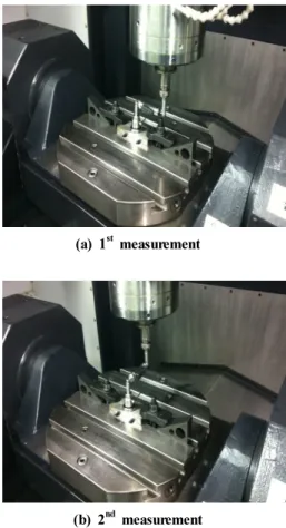
(a) 1st measurement
(b) 2nd measurement
Fig. 4 Double ball-bar measurement for a rotary table 반경 오차, 옵셋 오차 및 셋업 오차는 각각 다항식 및 상수로
모델링하여 식 (2)에서 추정한다. 특히 반경 오차의 경우 c=0, c=2π인 경우 C1-연속성을 구속조건으로 가지며, 이를 충족하 는 n차 다항식 모델은 식 (3)과 같다. 여기서 dijc는 반경 오차의 다항식 계수를 나타낸다.
(3)
오차를 추정하기 위하여 식 (3)을 식 (2)에 대입하고 정리하 면 식 (4)와 같다. 여기서 A는 C1-연속성을 나타내는 다항식의 항 및 삼각함수 항으로 이루어진 행렬이며 x는 다항식 계수, 옵셋 오차 및 셋업 오차로 이루어진 벡터이다. b는 볼바의 측정 편차 ΔR1, ΔR2로 이루어진 벡터이다.
(4)
따라서 최소 자승법을 적용하여 식 (4)에서 벡터 x를 계산하 고, 계산한 다항식 계수를 식 (3)에 대입함으로써 최종적으로 반경 오차, 옵셋 오차 및 셋업 오차를 추정한다.
3. 회전 테이블의 반경 오차 평가
ISO 230-2는 수치제어 이송축의 정확도(accuracy) 및 반복 정밀도(repeatability)를 평가하기 위한 규정이며, 직선 이송축 의 선형 위치 오차(linear positioning error) 및 회전 테이블의 각도 위치 오차(angular positioning error)를 대상으로 한다.
또한 직선 이송축 및 회전 테이블의 이송 기준 2000mm, 360°
에 따라 평가 항목을 나타낸다. 본 논문에서는 ISO 230-2의 측정 방법을 확장 적용하여 회전 테이블의 반경 오차를 평가한 다. 평가 대상으로 하는 회전 테이블의 이송 범위는 0~360°이 며, 이러한 경우 평가 항목은 아래와 같다.
E: 양방향 위치 편차(bi-directional systematic positional deviation of an axis)
E↑, E↓: 단방향 위치 편차(unidirectional systematic positional deviation of an axis)
M: 평균 양방향 위치 편차 범위(range of the mean bi- directional positional deviation of an axis)
B: 반전값(reversal value of an axis)
: 평균 반전값(mean reversal value of an axis)
(a) Measured data at 1st measurement
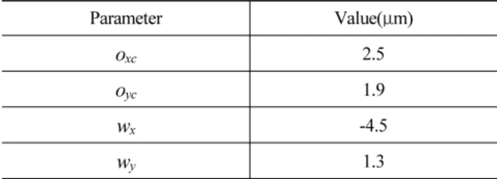
(b) Measured data at 2nd measurement Fig. 5 Measured data of double ball-bar Table 1 Estimated offset error and set-up error
Parameter Value(μm)
oxc 2.5
oyc 1.9
wx -4.5
wy 1.3
(a) Radial error δxc
(b) Radial error δyc
Fig. 6 Radial errors by eliminating offset error, set-up error from measured data
ISO 230-2에서 회전 테이블의 이송 범위가 0~360°인 경우 측정은 반시계방향(CCW)으로 5회전 정적측정 및 시계방향 (CW)으로 5회전 정적측정을 요구한다. 이에 따라 Fig. 4와 같 이 두산인프라코어 社의 5축 공작기계 VMD600-5AX에서 Renishaw 社의 볼바 QC20-W를 사용하여 측정을 진행한다.
측정은 환경 변화의 측정이 어려운 작업 현장에서 진행되었으 며, 이에 따라 환경 변화에 따른 측정 불확실도(measurement un- certainty)는 계산하지 않는다.
볼바의 측정 데이터는 Fig. 5와 같이 반시계방향의 경우 11.8 μm, 시계방향의 경우 8.8μm의 편차를 나타내고 있으며, 이는 회전 테이블의 기하학적 오차 및 셋업 오차의 영향이다. 반시계 방향과 시계방향의 경우 측정 데이터는 첫 번째 측정에서 최대 4.2μm의 최대 반전값을 가진다. 이는 회전 테이블의 이송 방향 을 반전하는 경우 X축 방향에 상대적으로 큰 오차가 나타나는 것을 의미한다.
측정 데이터를 사용하여 대표 반경 오차, 옵셋 오차 및 셋업 오차를 구하기 위하여 2번의 측정에서 각각 반시계방향 측정 데이터 및 시계방향 측정 데이터의 평균값을 계산하고 이를 식 (2)~(4)에 적용한다. 추정된 옵셋 오차와 셋업 오차는 Table 1 과 같으며, 이를 식 (2)에 대입하여 옵셋 오차와 셋업 오차를 제거하면 최종적으로 Fig. 6과 같이 평가하고자 하는 반경 오 차를 구한다.
반시계방향 및 시계방향에 대한 반경 오차를 사용하여 ISO 230-2의 평가 항목을 각각 계산하면 Table 2, Table 3과 같다.
Table 2 Test result for radial error δxc (Unit: μm)
i 1 2 3 4 5 6 7 8 9 10 11 12 13
Pos.(°) 0 30 60 90 120 150 180 210 240 270 300 330 360
Dir. CWCCWCWCCWCWCCWCWCCWCWCCWCWCCWCWCCWCWCCWCWCCWCWCCWCWCCWCWCCWCWCCW
δxc
j=1 -0.7 0.0 0.6 -1.0 -0.3 -3.8 -2.5 -6.9 -5.3 -9.3 -8.2 -10.6-10.1-11.2-11.4-10.3-11.2 -8.4 -9.6 -5.4 -6.4 -2.3 -3.1 -0.3 -0.7 0.4 2 -0.7 0.4 0.2 -0.9 -0.7 -3.8 -3.0 -7.0 -5.7 -9.5 -8.4 -11.1-10.3-11.4-11.6-10.7-11.2 -8.8 -9.6 -5.6 -6.5 -2.8 -3.0 -0.3 -0.4 0.5 3 -0.4 0.5 0.3 -0.9 -0.4 -3.8 -2.6 -6.9 -5.3 -9.4 -8.4 -11.0-10.0-11.3-11.2-10.6-11.1 -8.4 -9.4 -5.4 -6.6 -2.5 -3.0 -0.1 -0.4 0.6 4 -0.4 0.6 0.3 -0.7 -0.4 -3.8 -2.9 -7.0 -5.6 -9.5 -8.6 -11.3-10.4-11.7-11.6-10.9-11.3 -8.7 -9.6 -5.6 -6.7 -2.8 -3.0 -0.1 -0.5 0.6 5 -0.5 0.6 0.4 -0.7 -0.3 -3.6 -2.7 -6.9 -5.3 -9.4 -8.2 -11.1-10.1-11.4-11.3-10.5-11.1 -8.4 -9.5 -5.2 -6.5 -2.5 -3.0 -0.1 -0.3 0.7
Axis deviation Unidirectional(CW) Unidirectional(CCW) Bidirectional
Reversal value B Not applicable Not applicable 4.2
Mean reversal value Not applicable Not applicable 0.0
Range mean bidirectional positional deviation M Not applicable Not applicable 11.1
Systematic positional deviation E 11.9 12.0 12.0
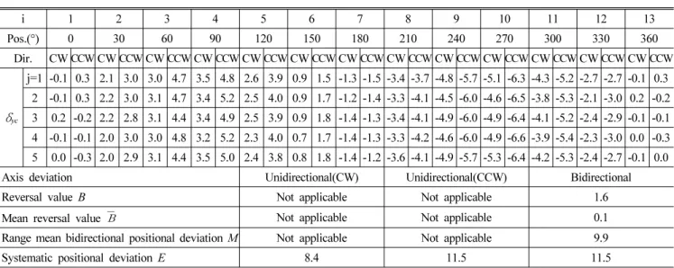
Table 3 Test result for radial error δyc (Unit: μm)
i 1 2 3 4 5 6 7 8 9 10 11 12 13
Pos.(°) 0 30 60 90 120 150 180 210 240 270 300 330 360
Dir. CWCCWCWCCWCWCCWCWCCWCWCCWCWCCWCWCCWCWCCWCWCCWCWCCWCWCCWCWCCWCWCCW
δyc
j=1 -0.1 0.3 2.1 3.0 3.0 4.7 3.5 4.8 2.6 3.9 0.9 1.5 -1.3 -1.5 -3.4 -3.7 -4.8 -5.7 -5.1 -6.3 -4.3 -5.2 -2.7 -2.7 -0.1 0.3 2 -0.1 0.3 2.2 3.0 3.1 4.7 3.4 5.2 2.5 4.0 0.9 1.7 -1.2 -1.4 -3.3 -4.1 -4.5 -6.0 -4.6 -6.5 -3.8 -5.3 -2.1 -3.0 0.2 -0.2 3 0.2 -0.2 2.2 2.8 3.1 4.4 3.4 4.9 2.5 3.9 0.9 1.8 -1.4 -1.3 -3.4 -4.1 -4.9 -6.0 -4.9 -6.4 -4.1 -5.2 -2.4 -2.9 -0.1 -0.1 4 -0.1 -0.1 2.0 3.0 3.0 4.8 3.2 5.2 2.3 4.0 0.7 1.7 -1.4 -1.3 -3.3 -4.2 -4.6 -6.0 -4.9 -6.6 -3.9 -5.4 -2.3 -3.0 0.0 -0.3 5 0.0 -0.3 2.0 2.9 3.1 4.4 3.5 5.0 2.4 3.8 0.8 1.8 -1.4 -1.2 -3.6 -4.1 -4.9 -5.7 -5.3 -6.4 -4.2 -5.3 -2.4 -2.7 -0.1 0.0
Axis deviation Unidirectional(CW) Unidirectional(CCW) Bidirectional
Reversal value B Not applicable Not applicable 1.6
Mean reversal value Not applicable Not applicable 0.1
Range mean bidirectional positional deviation M Not applicable Not applicable 9.9
Systematic positional deviation E 8.4 11.5 11.5
회전 테이블의 이송 방향의 변경에 따른 반전값 B는 반경 오차 δxc, δyc에서 각각 4.2μm, 1.6μm로서 상대적으로 큰 영향을 나 타내지 않으나, 위치 편차 M, E는 약 10μm로서 상대적으로 큰 영향을 나타낸다. 따라서 실험에 사용한 회전 테이블의 정확 도는 추정한 반경 오차 δxc, δyc를 직선 이송축 X, Y를 사용하 여 보정함으로써 개선시킨다.
4. 결 론
본 논문에서는 볼바를 사용하여 회전 테이블의 반경 오차를 평가하였으며, 결론은 다음과 같다.
(1) ISO 230-2의 오차 평가 방법과 볼바를 사용한 반경 오차 추정 방법을 활용하여 회전 테이블의 반경 오차 평가 방법
을 제안함.
(2) 제안한 방법을 적용하여 5축 공작기계에서 회전 테이블의 반경 오차를 평가함.
(3) 주요 평가 항목을 분석함으로써 회전 테이블의 정확도 개선 을 위한 개선 방안 마련함.
(4) 현재까지 연구에서 평가가 어려웠던 회전 테이블의 반경 오차를 평가함으로써 5축 공작기계의 정확도를 보다 정확 하게 평가함.
후 기
이 논문은 2011년도 정부(교육과학기술부)의 재원으로 한국 연구재단의 지원을 받아 수행됨 연구임(No. 2011-0020445), (No. 2011-0018392).
참 고 문 헌
(1) Mahbubur, R. M. D., Heikkala, J., Lappalainen, K., and Karjalainen, J. A., 1997, “Positioning Accuracy Improvement in Five-axis Milling by Post Processing,”
Int. J. Mach. T. & Manuf., Vol. 37, No. 2, pp. 223~236.
(2) Lamikiz, A., Lopez, L. N., Ocerin, O., Diez, D., and Maidagan, E., 2008, “The Denavit and Hartenberg Approach Applied to Evaluate the Consequences in the Tool Tip Position of Geometrical Errors in Five-Axis Milling Centres,” Int. J. Adv. Manuf. Tech., Vol. 37, No. 1~2, pp. 122~139.
(3) Tsutsumi, M., and Saito, A., 2003, “Identification and Compensation of Systematic Deviations Particular to 5-axis Machining Centers,” Int. J. Mach. T. & Manuf., Vol. 43, No. 8, pp. 771~780.
(4) Lee, D. M., Zhu, Z. K., Lee, K. I., and Yang, S. H., 2011, “Identification and Measurement of Geometric Errors for a Five-axis Machine Tool with a Tilting Head using a Double Ball-bar,” Int. J. Prec. Eng. &
Manuf., Vol. 12, No. 2, pp. 337~343.
(5) Kiridena, V. S. B., and Ferreira, P. M., 1994, “Kinematic Modeling of Quasistatic Errors of Three-axis Machining Centers,” Int. J. Mach. T. & Manuf., Vol. 34, No. 1, pp. 85~100.
(6) Kiridena, V. S. B., and Ferreira, P. M., 1994, “Parameter Estimation and Model Verification of First Order Quasistatic Error Model for Three-axis Machining Centers,” Int. J. Mach. T. & Manuf., Vol. 34, No. 1, pp. 101~125.
(7) Ramesh, R., Mannan, M. A., and Poo, A. N., 2000,
“Error Compensation in Machine Tools - A Review Part I: Geometric, Cutting-force Induced and Fixture- dependent Errors,” Int. J. Mach. T. & Manuf., Vol. 40, No. 9, pp. 1235~1256.
(8) Yang, S. H., Yuan, J., and Ni, J., 1996, “Accuracy Enhancement of a Horizontal Machining Center by Real-time Error Compensation,” J. Manuf. Sys., Vol.
12, No. 2, pp. 113~124.
(9) Lee, J. H., Liu, Y., and Yang, S. H., 2006, “Accuracy Improvement of Miniaturized Machine Tool: Geometric Error Modeling and Compensation,” Int. J. Mac. T. &
Manuf., Vol. 46, No. 12~13, pp. 1508~1516.
(10) Yang, S. H., Kim, K. H., Park, Y. K., and Lee, S. G.,
2004, “Error Analysis and Compensation for the Volumetric Errors of a Vertical Machining Centre using Hemispherical helix ball bar test,” Int. J. Adv.
Manuf. Tech., Vol. 23, No. 7~8, pp. 495~500.
(11) Lee, S. H., Seo, T. I., Cho, M. W., 2001, “On-machine Measurement Error Compensation using Ball-bar System,”
Trans. Korean. Soc. Mac. T. Eng., Vol. 10, No. 2, pp.
56~63.
(12) Okafor, A. C., and Ertekin, Y. M., 2000, “Derivation of Machine Tool Error Models and Error Compensation Procedure for Three Axes Vertical Machining Center using Rigid Body Kinematics,” Int. J. Mach. T. &
Manuf., Vol. 40, No. 8, pp. 1199~1213.
(13) ISO, 1996, Test Code for Machine Tools - Part 1:
Geometric Accuracy of Machines Operating under No-load of Finishing Conditions, ISO 230-1:1996, International Organization for Standardization, Geneva.
(14) Suh, S. H., Lee, E. S., and Jung, S. Y., 1998, “Error Modeling and Measurement for the Rotary Table of Five-axis Machine Tools,” Int. J. Adv. Manuf. Tech., Vol. 14, No. 9, pp. 656~663.
(15) Zargarbashi, S. H. H., and Mayer, J. R. R., 2006,
“Assessment of Machine Tool Trunnion Axis Motion Error, using Magnetic Double Ball Bar,” Int. J. Mach.
T. & Manuf., Vol. 46, No. 14, pp. 1823~1834.
(16) Hong, C., Ibaraki, S., and Matsubara, A., 2011, “Influence of Position-dependent Geometric Errors of Rotary Axes on a Machining Test of Cone Frustum by Five-axis Machine Tools,” Prec. Eng., Vol. 35, No. 1, pp. 1~11.
(17) ISO, 1996, Test Code for Machine Tools - Part 7:
Geometric Accuracy of Axes of Rotation, ISO 230-7:
1996, International Organization for Standardization, Geneva.
(18) ISO, 1996, Test Code for Machine Tools - Part 2:
Determination of Accuracy and Repeatability of Positioning Numerically Controlled Axes, ISO 230-2:
2006, International Organization for Standardization, Geneva.
(19) Lee, K. I., Lee, D. M., and Yang, S. H., 2012,
“Parametric Modeling and Estimation of Geometric Errors for a Rotary Axis using Double Ball-Bar,” Int.
J. Adv. Manuf. Tech., DOI: 10.1007/s00170-011-3834-0.
(in press)