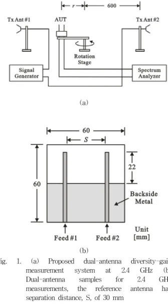
A Simple Dual-Antenna Diversity Gain Measurement System at 2.4GHz
4
0
0
전체 글
(2)
수치
관련 문서
Gain Boosting applied to both g pp signal path and load devices... CMFB Triode Example
This paper proposes the improved real time object detection and distance measurement system using IR-UWB radar.. Firstly, the IR-UWB signal is applied for
In this paper, the variable capacitors and the superconducting relay antenna were applied to the superconducting WPT system to increase efficiency and the transmission distance
The reason why I choose HAPPEN group and EXPERIENCE group to do research is that in English HAPPEN-words and EXPERIENCE-words show diversity in
The developed FPGA based high-speed multi-channel DAQ system includes smoothing, triggering, and pulse height measurement. Considering the stable performance and
Example 16.5: Small-Signal Gain Variation of NMOS Inverter.. the small-signal gain is the largest in
• Apply the principle of impulse and momentum. Since the initial momenta is zero, the system of impulses must be equivalent to the final system of momenta. • Assume
To create a smooth path with continuous position and velocity, we start with the linear function but add a parabolic blend region at each path point.. During the blend portion
