DOI: https://doi.org/10.14579/MEMBRANE_JOURNAL.2017.27.2.121
1. 서 론
1)
고분자 분리막은 용이한 가공성, 낮은 생산가격, 우 수한 분리성능 등의 장점으로 인하여, 생명공학, 식품공
학 및 에너지-환경 공학 분야 등에서 다양하게 사용되 고 있다[1-5]. 이러한 고분자 분리막의 가장 중요한 특 성은 선택적 투과능력으로서, 고성능 분리막을 제조하 기 위해서는 분리막을 구성하고 있는 고분자의 구조적
†Corresponding author(e-mail: [email protected], http://orcid.org/0000-0002-5601-065X)
에너지-환경 분야용 분리막의 Mesoscale Simulation 동향 연구
박 치 훈*,†⋅남 상 용**
*경남과학기술대학교(GNTECH) 에너지공학과, **경상대학교 나노신소재융합공학과, 공학연구원 (2017년 4월 25일 접수, 2017년 4월 28일 수정, 2017년 4월 28일 채택)
Mesoscale Simulation of Polymeric Membranes for Energy and Environmental Application
Chi Hoon Park*,† and Sang Yong Nam**
*Department of Energy Engineering, Gyeongnam National University of Science and Technology (GNTECH), Jinju 52725, Korea
**Department of Materials Engineering and Convergence Technology, Engineering Research Institute, Gyeongsang National University, Jinju 52828, Korea
(Received April 25, 2017, Revised April 28, 2017, Accepted April 28, 2017)
요 약: Mesoscale simulation은 원자의 그룹을 묶어서 하나의 단위로서 계산을 수행하는 전산모사 기술로 ns~µs의 시간 및 nm~µm의 크기까지 모사가 가능하다. 이러한, mesoscale simulation에는 (1) 입자 자체의 움직임을 계산하여 시스템을 모 사하는 particle-based mesoscale, (2) 입자의 움직임이 아닌 chemical potential filed나 density field 등의 변화를 계산하여 시 스템을 모사하는 field theory 등의 방법 등이 있는데, 두 방법 모두 고분자의 거시적 특성을 살펴보기 위한 강력한 전산모사 기술로서, 에너지-환경 분야용 고분자 분리막의 다양한 응용분야에서 활용되고 있다. 기존에는 주로 블록 공중합체 분야에서 연구결과들이 보고되었으나, 최근 들어 실제 고분자 분리막의 제조 조건 등을 모사한 연구 결과와 같이 좀 더 응용 분야에 가까운 다양한 에너지-환경용 고분자 분리막 관련 연구가 진행되고 있다. 이온 교환막의 경우에는 이온 전달 채널 형성을 분 석 및 예측하기 위한 다양한 mesoscale simulation 결과들이 발표되고 있고, 최근에는 CNT, graphene 등의 나노 첨가물 소재 에 대한 연구도 활발히 진행되고 있다. 본 총설에서는 mesoscale simulation 관련 연구에 대한 동향을 정리하고, 어떤 분야에 서 유용하게 활용 가능한지 제시하며, 에너지-환경 분야에 종사하는 분리막 연구자들이 mesoscale simulation 기술에 좀 더 쉽게 다가갈 수 있는 기회를 제공하고자 한다.
Abstract: Mesoscale simulation is a type of molecular simulation techniques where groups of atoms are defined as a single bead for calculations, and accordingly, is possible to simulate longer time (ns~µs) and bigger size (nm~µm). There are two types of mesoscale simulations : (1) particle-based mesoscale which simulates the system by calculating the move- ment of the particles themselves and (2) field theory which simulates the system by calculating changes in the chemical po- tential filed or density field. Mesoscale simulations are powerful tools to study the macroscopic properties of polymers for various applications of energy and environment. In this review, we report the trends and useful information in mesoscale simulation and provide an opportunity for membrane researchers working in the energy-environment field to understand mes- oscale simulation techniques.
Keywords: energy & environment, polymeric membranes, molecular simulation, mesoscale simulation
시뮬레이션 대상 고분자의 크기 및 모사 시간의 확대를 가져왔으며, 이로 인하여 복잡한 고분자 구조 및 특성 분석에 있어서도 매우 강력한 연구방법으로 자리 잡았으 며, 그중에서 mesoscale simulation은 ns~µs의 시간 및 nm~µm의 크기까지 모사가 가능한 시뮬레이션 기술로 서, 고분자의 상분리, composite, blend, surfactant의 mi- celle formation 등의 연구에 많이 활용되어 왔다[7,8].
원자 개개의 움직임을 모사는 하는 분자동역학 (Molecular dynamics; MD) 전사모사에서와 달리 meso- scale simulation에서는 원자의 그룹을 묶어서 하나의 단위로서 계산을 수행하는 방식(renormalization)을 채 택한다[8]. 따라서, 그만큼 계산하는 양이 줄게 되며, MD에 비하여 더 큰 시스템의 계산이 가능하게 된다.
이러한 mesoscale simulation에는 입자 자체의 움직임을 계산하여 시스템을 모사하는 particle-based mesoscale, 입자의 움직임이 아닌 chemical potential filed나 den- sity field 등의 변화를 계산하여 시스템을 모사하는 field theory 등의 방법 등이 있다[8]. 전자의 예시로서 dissipative particle dynamics에 기반한 DPD[9]와 후자 의 예시로서 dynamic mean-field density functional theory에 기반한 MesoDyn이라는 모듈이 널리 사용되 고 있다[10].
이들 두 방법을 포함하는 mesoscale simulation에서 는 먼저 각 고분자의 구조를 coarse grained bead로 구 성된 Gaussian chain으로 표현을 하게 된다. 이때, 각 고분자를 이루는 bead의 개수는 다음 식과 같이 계산된다.
Nbead = Mpolymer / (Mmonomer × Cn) (1)
이때, Nbead는 총 bead의 개수, Mpolymer와 Mmonomer는 각각 해당 고분자와 모노머의 분자량, Cn은 character- istic ratio로 주어진다. 이때에 각 bead의 interaction pa- rameter를 계산하여, 이를 바탕으로 mesoscale simu- lation을 수행하게 된다. Interaction parameter를 계산할 때에는 다음의 Flory-Huggins χ parameter에 기반하여 계산이 이루어진다.
bead repulsion parameter 값을 계산하게 되는데, 예를 들어, DPD에서는 입력 변수 aij를 아래의 식 (3)과 같이 계산하여 bead-bead repulsion parameter를 얻게 된다[9].
(3)
또 다른 예로서, MesoDyn에서는 입력 변수를 다음과 같은 식에 따라 계산을 하여 simulation을 수행한다[10].
ν-1 εAB = χABRT (4)
이때, ν-1 εAB는 두 bead 간의 repulsion parameter 이고, R은 기체 상수, T는 온도로서 주어진다.
실제 mesoscale simulation을 수행하기 위해서는, 위 에 예시로 든 bead-bead repulsion parameter 이외에도 다양한 입력 변수 설정이 필요하지만, 세세한 설정 방 법은 각각의 관련 논문을 참고할 것을 추천하며, 본 총 설에서는 전산모사에 경험이 없는 연구자들도 관심을 가질 수 있도록, mesoscale simulation의 활용 예시 위 주로 소개를 하고자 한다.
2. Mesoscale simulation을 이용한 구조 해석
Mesoscale simulation은 고분자의 거시적 거동을 모 사하기에 적당한 크기 및 시간 범위를 가지고 있기 때 문에, 특히 고분자 블렌드 분야에 많이 사용되어 왔다.
Fig. 1은 MesoDyn을 이용하여 고분자 블렌드의 상분리 거동에 관한 실험 이미지와 전산모사 이미지를 비교한 연구로서, 실제 polystyrene-block-polybutadiene-block- polystyrene 블록 공중합체에서 일어나는 상분리 현상 을 매우 근사하게 모사하고 있다[11]. 이러한 상분리 현 상의 효과적인 모사 결과는 분리막 분야에서 중요한 제 막 방법 중 하나인 상분리법에 mesoscale simulation이 적용 가능하다는 것을 나타내며, 이는 관련 연구들을 통하여 입증되었다. Immersion precipitation을 통한 상
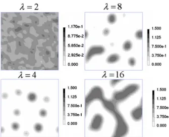
전이 제조법을 DPD를 이용하여 모사한 연구[12]에서 는, 검은색의 고분자 속으로 non-solvent가 확산해 들어 가는 것을 시간에 따라서 관찰할 수 있으며, 결과적으 로 다공성 상전이 분리막이 형성되는 과정을 효과적으 로 나타내고 있다. 또한, 해당 연구에서는 고분자 주쇄 의 길이 및 solvent/non-solvent의 크기 및 조성에 따른 분리막의 모폴로지 특성차이에 대한 연구를 DPD를 통 하여 성공적으로 수행하였다. 또 다른 분리막 제조 방법 중 하나인 thermally induced phase separation (TIPS)의 경우에도 DPD를 이용하여 전산모사를 수행한 연구 결 과가 보고되었다[13,14]. 이를 통하여, TIPS 공정변수 들, 온도조건, 고분자 주쇄 길이, 희석제 종류 등에 따 른 다양한 고분자 분리막의 모폴로지 변화를 조사하였 다(Fig. 2).
이러한 상분리 거동의 모사를 통한 고분자 분리막 제 조 조건에 관한 전산모사는 mesoscale simulation의 다 른 응용 분야에 비하여 상대적으로 최근에 연구가 이루 어지기 시작해서, 아직 다양한 연구 결과들이 보고되지 는 않았다. 그러나, 기존에 고분자 전산모사의 주를 이 루던 MD에서는 이러한 시간 및 크기의 시뮬레이션이 거의 불가능하였기 때문에, mesoscale simulation의 장 점을 가장 잘 살릴 수 있는 분야로서, 앞으로 더욱 각 광받을 것으로 기대된다.
3. 고분자 전해질막의 이온 전달 채널 구조 해석
고분자 전해질막에서 선택적 투과 대상이 되는 이온 은 수화상태에서 내부에 형성되는 이온 전달 채널을 통 (a)
(b)
Fig. 1. (a) Schematic phase diagram of a thin film of polystyrene-block-polybutadiene-block-polystyrene block copolymer. (b) Nucleation and growth of a cluster of perforations forming a perforated lamella phase (upper : snapshots from SFM images, lower: images from mesoscale simulation results)(Reprinted with permission from[11]. Copyright 2004 Macmillan Publishers Ltd.).
Fig. 2. Morphological changes with different polymer chain lengths by DPD simulation (Reprinted with permission from[14].
Copyright 2013 Elsevier).
하여 전달되게 된다[15-17]. 따라서, 이온 전달 채널을 하는 수화 채널이 얼마나 효과적으로 형성되는지는 고 분자 전해질막의 성능을 결정하는 가장 중요한 요소 중 하나이다. 그러나, 실험만으로는 이러한 수화 채널의 모 폴로지를 정확하게 파악하는 것이 매우 어렵기 때문에, 전산모사 기술을 이용하여 이를 밝혀내고자 하는 다양 한 연구가 진행되어 왔다[18-20]. 그러나, 대부분의 경 우 MD를 활용하여 연구가 진행되었기 때문에, 모사 시 간 및 크기의 제한으로 인하여 부분적인 물분자 클러스 터 형성에 대한 정보 위주로 연구 결과가 제시가 되었 고, 실험을 통해서 제시되고 있는 수 nm 대의 크기를 갖는 수화 채널에 대한 구조를 모사하는 데에는 한계를 보여 왔다.
앞서 언급하였듯이, mesoscale simulation에서는 이러 한 크기의 전산모사가 가능하고, 특히 상분리 현상을 모사하는 데에 강점을 갖고 있기 때문에, 고분자의 친 수성/소수성 영역의 상분리 현상과 이렇게 형성된 친수 영역에 형성되는 수화 채널에 대한 좀 더 명확한 구조 적 차이를 보여주는데 효과적이다. Fig. 3는 대표적인 양이온 교환 고분자 전해질막인 Nafion이 수화됨에 따 라서, 수화 채널이 형성되는 모습을 MesoDyn을 이용하 여 보여주고 있다[21]. 일반적으로 널리 알려져 있는 바 와 같이, 나피온은 낮은 수화상태에서도 물분자가 클러 스터를 형성하며 효과적인 이온전달 채널을 갖게 되는 데, mesoscale simulation에서도 이러한 상분리 효과가
잘 나타나고 있다. DPD를 통해서도 이러한 나피온의 수화 채널 형성에 관한 연구가 진행되었는데, Fig. 4에 서 그 결과를 확인할 수 있으며, 추가적으로 동일한 과 불화불소계 고분자 주쇄 구조에 작용기의 길이가 서로 다른 두 종류의 고분자 전해질의 mesoscale simulation 을 수행하여, 작용기 변화에 따른 수화 채널 모폴로지 의 변화를 관찰하였다[22]. 탄화수소계 고분자 주쇄를 갖는 고분자 전해질막의 수화 채널 형성에 대한 meso- scale simulation 또한 다양하게 진행되고 있는데, 일반 Fig. 3. Contour plots of water (W) density in a two di-
mensional (2D) cross section at increasing water contents (λ = # of water molecules / # of sulfonic acid groups) (Reprinted with permission from[21]. Copyright 2006 AIP Publishing).
(a) (b)
Fig. 4. Contour plots of the density of water, as W beads, shown as a two dimensional cross section for Nafion with an EW = 1244 : (a) λ = 9; and (b) λ = 16 (Reprinted with permission from[22]. Copyright 2008 The Royal Society of Chemistry).
(a) (b)
Fig. 5. Snapshots showing the structural evolution of wa- ter-containing sPEEK-60 (left column) and Nafion (right column) during the DDFT runs, at a hydration level of φ
= 0.33 (Reprinted with permission from[23]. Copyright 2010 The Royal Society of Chemistry).
적으로 알려진 바와 같이 동일한 water volume fraction 에서 상대적으로 수화 채널이 약하게 형성이 되는 것이 관찰되었다(Fig. 5)[23].
4. 고분자 복합막 구조 해석
고분자 분리막의 성능 향상을 위한 방법 중의 하나로 서, silica, carbon nanotubes (CNT), graphene 등의 첨 가물 도입을 통한 복합막 제조법이 널리 사용되고 있다 [24-26]. 이러한 복합막의 제조에 있어서, 이러한 첨가 물의 혼화성 문제는 고분자 분리막의 성공적인 제조를 결정하는 가장 중요한 요소 중 하나이다. 일반적으로, silica, CNT 및 graphene 등은 고분자 용액과 혼합시에 응집현상을 일으키면서 분리/침적되게 되는데, 적정한 solubility parameter를 갖는 용매 선정, 고분자 구조 등 다양한 요소들의 영향을 받는다. Fig. 6은 DPD를 이용 하여 고분자-CNT 복합체 제조 조건에 대한 전산모사를 수행한 결과이다[27]. 이를 위하여, 우선 MD를 이용하 여 다양한 고분자 및 CNT의 solubility parameter를 계
산하고, 이를 바탕으로 적절한 고분자-CNT 조합을 제 시하였으며, 추가적인 작용기를 CNT에 도입하여 분산 에 미치는 영향을 관찰하였다[28].
이러한, 고분자 복합체에 대한 mesoscale simulation 기술의 활용은 복합체 제조 조건에 있어서 가장 중요한 요소인 분산 문제를 해결하는 데에 있어서 매우 효과적 인 이론적인 배경을 제시하고 있음에도 불구하고, 입력 변수 설정 등에 있어서 다양한 이론 및 전산모사 경험 을 필요로 하기 때문에, 앞 장에서 논의한 고분자 블렌 드, 구조특성 전산모사 등에 비하여 아직 많은 연구가 이루어지지 못하고 있다. 그러나, 실험적인 관점에서 가 장 널리 사용되고 있는 solubility parameter가 고분자나 크기가 큰 CNT, graphene 등의 첨가물에 적용되기 어 려운 이론적인 한계를 갖고 있기 때문에, 추가로 모폴 Fig. 6. To predict the structural mean free path of a gas
molecule in the SWCNT aerogel, a 3D network model was created. The mesoscale model is 1.05 × 1.05 × 1.05 µm3 with periodic boundary conditions (a 300 × 300 × 300 nm3 sub-section is shown). The SWCNTs are repre- sented by a string of beads and are each 1 µm long. A gas molecule was randomly placed in the model (i.e., the sphere) and moved along a randomly chosen direction un- til a collision with a SWCNT occurred. This process was repeated 10000 times and the free paths were averaged to extract the structural mean free path (Reprinted with per- mission from [27]. Copyright 2012 John Wiley and Sons).
(a)
(b)
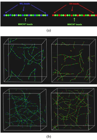
Fig. 7. Coarse-grained models(A) and mesoscale simulation results of 0.5 wt% (B) and 1 wt% (C) of functionalized MWCNT models where MWCNTs (green color) are em- bedded with amine groups (left; blue color) and hydroxyl groups (right; red color), respectively. Here, P84 models were hidden (Reprinted with permission from[29].
Copyright 2016 Elsevier).
안이 없는 상황이다. 그러나, Fig. 7에서와 같이 MD 기 술과 mesoscale simulation 기술을 통하여 분산성 향상 을 위한 표면처리 조건을 제시할 수 있고, 또한 표면처 리 시에 어떤 부위에 작용기가 도입될 것인지를 추정하 는 것도 가능하다[29]. 따라서, 앞으로 graphene 등의 나노 물질의 복합체 제조 분야에서 그 가능성이 기대 된다.
5. 결 론
Mesoscale simulation은 고분자의 거시적 특성을 살 펴보기 위한 강력한 전산모사 기술로서, 에너지-환경 분야용 고분자 분리막에 있어서 응용분야가 매우 넓다.
전통적으로 널리 활용되어 온 고분자 블렌드의 모폴로 지 분석의 경우, 특히 블록 공중합체 분야에서 많은 연 구결과들이 보고되었다. 그러나, 최근 들어서는 이러한 이론적인 연구보다는 실제 고분자 분리막의 제조 조건 등을 모사하는 좀 더 응용 분야에 가깝고 다양한 에너 지-환경용 고분자 분리막 관련 연구들이 진행되고 있 다. 특히, 역삼투, 전기투석, 연료전지용 전해질 막 등에 널리 사용되고 있는 이온교환막의 경우에는 가장 중요 한 성능 지표 중 하나인 이온 전달 채널 형성을 분석 및 예측하기 위한 다양한 mesoscale simulation 결과들 이 발표되고 있다. 또한, 최근에는 CNT, graphene 등의 나노 첨가물 소재에 대한 연구도 활발히 진행되고 있으 며, 앞으로도 전망이 밝은 분야 중 하나이다.
하지만, 동시에 mesoscale simulation의 한계도 명확 하게 나타나고 있는데, 무엇보다 앞서 언급한 특정 분 야 이외에는 분리막 분야에서 사용된 적이 많지 않기 때문에 관련 정보를 얻기가 힘들고, 따라서 전산모사에 익숙하지 않은 연구자가 접근하기가 어렵다. 또한, mesoscale simulation의 특성상 bead 선정 단계에서부 터 여러 가지 가정을 바탕으로 전산모사가 진행되다 보 니, 검증 단계에서 이러한 가정이 타당한지를 규명하는 데 많은 노력이 필요하다.
1. T. H. Lee, H. D. Lee, and H. B. Park, “Current research trends in polyamide based nanocomposite membranes for desalination”, Membr. J., 26, 351 (2016).
2. J. I. Ha and T. B. Kang, “Separation of H2 and N2
gases by PDMS-chitosan composite membranes”, Membr. J., 23, 418 (2013).
3. H. W. Kim and H. B. Park, “Gas transport behav- ior of polydopamine-coated composite membranes”, Membr. J., 23, 136 (2013).
4. D. J. Kim and S. Y. Nam, “Development and ap- plication trend of bipolar membrane for electro- dialysis”, Membr. J., 23, 319 (2013).
5. C. H. Park, H. S. Kim, and Y. M. Lee, “Surface modification of proton exchange membrane by in- troduction of excessive amount of nanosized sili- ca”, Membr. J., 24, 301 (2014).
6. J. C. Jansen, M. MacChione, E. Tocci, L. De Lorenzo, Y. P. Yampolskii, O. Sanfirova, V. P.
Shantarovich, D. Hofmann, and E. Drioli, “Com- parative study of different probing techniques for the analysis of the free volume distribution in amorphous glassy perfluoropolymers”, Macromolecules, 42, 7589 (2009).
7. C. H. Park, D. J. Kim, and S. Y. Nam, “Molecular dynamics (MD) study of polymeric membranes for gas separation”, Membr. J., 24, 341 (2014).
8. J. Huh and W. H. Jo, “Simulation of self-as- sembled structures in macromolecular systems:
From atomistic model to mesoscopic model”, Polymer(Korea), 30, 453 (2006).
9. P. Español and P. Warren, “Hydrodynamics from dissipative particle dynamics”, Phys. Rev. E, 52, 1734 (1995).
10. J. T. Wescott, Y. Qi, L. Subramanian, and T. W.
Capehart, “Mesoscale simulation of morphology in hydrated perfluorosulfonic acid membranes”, J.
Chem. Phys., 124, 134702 (2006).
11. A. Knoll, K. S. Lyakhova, A. Horvat, G. Krausch, G. J. A. Sevink, A. V. Zvelindovsky, and R.
Magerle, “Direct imaging and mesoscale modelling of phase transitions in a nanostructured fluid”, Nat.
Mater., 3, 886 (2004).
12. X.-L. Wang, H.-J. Qian, L.-J. Chen, Z.-Y. Lu, and Z.-S. Li, “Dissipative particle dynamics simulation on the polymer membrane formation by immersion precipitation”, J. Membr. Sci., 311, 251 (2008).
13. Y.-D. He, Y.-H. Tang, and X.-L. Wang,
“Dissipative particle dynamics simulation on the membrane formation of polymer-diluent system via thermally induced phase separation”, J. Membr.
Sci., 368, 78 (2011).
14. Y.-h. Tang, Y.-d. He, and X.-l. Wang, “Three-di- mensional analysis of membrane formation via thermally induced phase separation by dissipative particle dynamics simulation”, J. Membr. Sci., 437, 40 (2013).
15. C. H. Park, C. H. Lee, M. D. Guiver, and Y. M.
Lee, “Sulfonated hydrocarbon membranes for me- dium-temperature and low-humidity proton ex- change membrane fuel cells (PEMFCs)”, Prog.
Polym. Sci., 36, 1443 (2011).
16. C. H. Park, S. Y. Lee, D. S. Hwang, D. W. Shin, D. H. Cho, K. H. Lee, T.-W. Kim, T.-W. Kim, M.
Lee, D.-S. Kim, C. M. Doherty, A. W. Thornton, A. J. Hill, M. D. Guiver, and Y. M. Lee,
“Nanocrack-regulated self-humidifying membranes”, Nature, 532, 480 (2016).
17. K.-D. Kreuer, S. J. Paddison, E. Spohr, and M.
Schuster, “Transport in proton conductors for fuel-cell applications: Simulations, elementary re- actions, and phenomenology”, Chem. Rev., 104, 4637 (2004).
18. C. H. Park, C. H. Lee, J.-Y. Sohn, H. B. Park, M.
D. Guiver, and Y. M. Lee, “Phase separation and water channel formation in sulfonated block copo-
lyimide”, J. Phys. Chem. B, 114, 12036 (2010).
19. S. S. Jang, V. Molinero, T. Çaǧin, and W. A.
Goddard Iii, “Nanophase-segregation and transport in nafion 117 from molecular dynamics simu- lations: Effect of monomeric sequence”, J. Phys.
Chem. B, 108, 3149 (2004).
20. P. Y. Chen, C. P. Chiu, and C. W. Hong,
“Molecular structure and transport dynamics in Nafion and sulfonated poly(ether ether ketone ke- tone) membranes”, J. Power Sources, 194, 746 (2009).
21. J. T. Wescott, Y. Qi, L. Subramanian, and T. W.
Capehart, “Mesoscale simulation of morphology in hydrated perfluorosulfonic acid membranes”, J.
Chem. Phys., 124, 134702 (2006).
22. D. Wu, S. J. Paddison, and J. A. Elliott, “A com- parative study of the hydrated morphologies of perfluorosulfonic acid fuel cell membranes with mesoscopic simulations”, Energy. Environ. Sci., 1, 284 (2008).
23. P. V. Komarov, I. N. Veselov, P. P. Chu, and P.
G. Khalatur, “Mesoscale simulation of polymer electrolyte membranes based on sulfonated poly(ether ether ketone) and Nafion”, Soft Matter, 6, 3939 (2010).
24. C. H. Park, H. K. Kim, C. H. Lee, H. B. Park, and Y. M. Lee, “Nafion® nanocomposite mem- branes: Effect of fluorosurfactants on hydrophobic silica nanoparticle dispersion and direct methanol fuel cell performance”, J. Power Sources, 194, 646 (2009).
25. B. J. Hinds, N. Chopra, T. Rantell, R. Andrews, V. Gavalas, and L. G. Bachas, “Aligned multi- walled carbon nanotube membranes”, Science, 303, 62 (2004).
26. H. W. Kim, H. W. Yoon, S.-M. Yoon, B. M.
Yoo, B. K. Ahn, Y. H. Cho, H. J. Shin, H. Yang, U. Paik, S. Kwon, J.-Y. Choi, and H. B. Park,
“Selective gas transport through few-layered gra- phene and graphene oxide membranes”, Science, 342, 91 (2013).
27. S. N. Schiffres, K. H. Kim, L. Hu, A. J. H.
theory and mesoscale simulations”, Mol. Simul., J. Membr. Sci., 514, 195 (2016).
![Fig. 2. Morphological changes with different polymer chain lengths by DPD simulation (Reprinted with permission from[14]](https://thumb-ap.123doks.com/thumbv2/123dokinfo/5469234.439763/3.892.180.708.432.694/morphological-changes-different-polymer-lengths-simulation-reprinted-permission.webp)