• 검색 결과가 없습니다.

I .INTRODUCTION D. Cha A. Babajanyan O. Galstyan · H. Lee · J. Park · Y. Lee · K. Lee Magneto-opticalImagingUsingBi Y Fe O ThinFilmsPreparedonGlassSubstratesbyUsingtheMODMethod

N/A
N/A
Protected

Academic year: 2021

Share "I .INTRODUCTION D. Cha A. Babajanyan O. Galstyan · H. Lee · J. Park · Y. Lee · K. Lee Magneto-opticalImagingUsingBi Y Fe O ThinFilmsPreparedonGlassSubstratesbyUsingtheMODMethod"

Copied!
4
0
0

로드 중.... (전체 텍스트 보기)

전체 글

(1)

Vol. 64, No. 11, November 2014, pp. 1089∼1092

New Physics: Sae Mulli, DOI: 10.3938/NPSM.64.1089

Magneto-optical Imaging Using Bi 2 Y 1 Fe 5 O 12 Thin Films Prepared on Glass Substrates by Using the MOD Method

O. Galstyan · H. Lee · J. Park · Y. Lee · K. Lee

Department of Physics and Basic Science Institute for Cell Damage Control, Sogang University, Seoul 121-742, Korea

A. Babajanyan

Department of Radiophysics, Yerevan State University, A. Manoogian 1, Yerevan 0025, Armenia

D. Cha

Department of Physics, Kunsan National University, Gunsan 573-701, Korea (Received 25 September 2014 : revised 7 October 2014 : accepted 7 October 2014)

We discuss the preparation procedure for the fabrication of magneto-optical, bismuth-doped, yttrium-iron-garnet (Bi

2

Y

1

Fe

5

O

12

: Bi-YIG) thin films on glass substrates by using a metal-organic decomposition technique. Detailed fabrication conditions for the films with about a 11
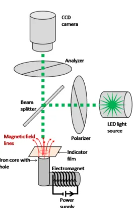
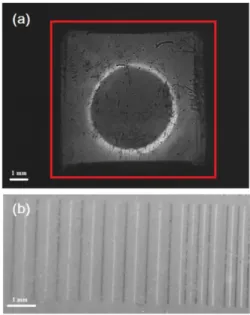
/µm Fara- day rotation angle are presented. The X-ray diffraction spectra indicate that the samples were polycrystalline. The thickness of the films were about 0.8 µm. The high Faraday rotation angle, the low optical absorption and the in-plane magnetic anisotropy of the Bi-YIG films makes them great candidates to be used as indicators for magneto-optical visualization systems. Using these indicator films, we imaged the magnetic domains in magnetic materials.

PACS numbers: 74.25.Ha, 75.47.Np, 75.50.Ss

Keywords: Bi-YIG, Faraday rotation, Metal-organic decomposition method, Magnetic domain

I. INTRODUCTION

Yttrium iron garnet (Bi x Y 3−x Fe 5 O 12 ) is a material of choice for the magneto-optical and microwave applica- tions because of its high Faraday rotation [1], low op- tical losses in visible and near-infrared region, smallest linewidth (∆H) in ferromagnetic resonance and control- lable magnetic properties [2]. In information, communi- cation and data sensing technologies through increasing magneto-optical properties in garnet materials one can achieve higher data capacitance, high speed magneto- optical switching and more sensitive sensors for magneto- optical microscopy [3]. Hansen et al. in [4] showed that by increasing the concentration of substituted bismuth in yttrium iron garnet thin films, the larger Faraday rota- tion angles can be achieved. Fully substituted Bi 3 Fe 5 O 12

is the ideal material for the magneto-optical applications

E-mail: [email protected]

but because it is thermodynamically unstable it is impos- sible to prepare thin films on non-garnet substrates like glass [5].

There are several preparation techniques of garnet thin films, such as liquid phase epitaxy (LPE) [2], radio- frequency magnetron sputtering method [6], pulsed laser deposition (PLD) [7], the sol-gel method [8], and the metal-organic decomposition method (MOD) [5]. For the synthesis of Bi-YIG films we used the MOD method because it is inexpensive, simple, and allows precise con- trol of the composition of the MOD solution and the for- mation over the large area. Furthermore, in comparison with the melting point of Bi-YIG the MOD method re- quires relatively low temperature, so this property gives us the possibility to make thick and multilayer structures on a glass substrate [9].

Usually garnet films easier to deposit on garnet sub- strates because morphological instabilities due to mis- 1089

This is an Open Access article distributed under the terms of the Creative Commons Attribution Non-Commercial License

(http://creativecommons.org/licenses/by-nc/3.0) which permits unrestricted non-commercial use, distribution, and reproduction in any

medium, provided the original work is properly cited.

(2)

1090 New Physics: Sae Mulli, Vol. 64, No. 11, November 2014

Fig. 1. (Color online) The schematic diagram of magneto-optical imaging setup.

fit stress are avoided by the use of lattice matched sub- strates. Considering large size fabrication and availabil- ity, use of the non-garnet substrates such as glass should be important. For example there is a great need of non- reciprocal devices in integrated photonic devices which makes it important to find technique for the preparation of garnet materials on non-garnet substrates. There are several publications which deal with the films prepared on semiconductor or amorphous substrates [3,9,10].

In this paper we present the details of preparation of Bi x Y 3−x Fe 5 O 12 (x = 2) films by the MOD method on glass substrates using low sintering temperature. By the sputtering of Al mirror on the film surface we used sam- ples as indicator films for the magneto-optical imaging system. We discuss the characterization of crystalline structure, magnetic and magneto-optical properties of the samples.

II. EXPERIMENTS

We prepared Bi-YIG films by spin coating of a metal-organic solution which chemical composition is Bi 2 Y 1 Fe 5 O 12 on a glass substrate at 3000 rpm for 30

seconds. The deposited solution was dried at 70 C for 30 minutes. After drying we pre-annealed the samples at 450 C for 30 minutes in order to decompose carboxy- lates into metal oxides and bring them to the amorphous phase. These processes have been repeated 20 times to achieve the thicker films with thicknesses of 0.8 mm. Fi- nally, samples were post-annealed in a furnace at 620

◦ C for 3 hours for the final crystallization process. All thermal treatments were done in air [12].

The experimental setup for Faraday rotation measure- ments is represented in ref. [12]. Faraday rotation of the prepared sample was measured to be about 11 /µm.

Figure 1 shows schematic diagram of magneto-optical imaging setup. As a light source we used Thorlabs LED M530L2 which has a dominant wavelength of 530 nm [13]. Light passes through the polarizer, beam splitter and indicator film. Film is placed in front of the surface of a magnetic field source: electromagnet. The strength of magnetic field is controlled by the power supply. Be- cause of the parallel magnetic field along the light propa- gation direction in garnet medium, rotation of the plane of polarization: Faraday rotation occurs. After reflection from Al mirror light beam crosses twice the garnet layer doubling the rotation angle in this way. The Faraday rotation angle depends on the magnetic field strength.

Reflected light received by the CCD camera through the beam splitter and analyzer. Polarizer and analyzer are set in crossed position. If the analyzer will be rotated at an (π/2 − θ) compared to the polarizer the measured light intensity will be given by the following equation:

I = I 0 sin 2 (θ − θ F ) ≈ I 0 (θ − θ F ) 2 , (1)

where I is the detected light intensity, I 0 is the initial light intensity, and θ F is Faraday rotation angle. We need to take into account that light passes film for two times. Then light intensity is transformed by CCD ma- trix into an electric signal which is digitized and dis- played on the monitor.

The crystal structure and magnetic properties of Bi-

YIG films were investigated by X-ray diffractometer

(XRD) and by vibrating sample magnetometer (VSM),

respectively.

(3)

Magneto-optical Imaging Using Bi

2

Y

1

Fe

5

O

12

Thin Films Prepared on Glass Substrates· · · – O. Galstyan et al. 1091

Fig. 2. X-ray diffraction pattern of the prepared films.

Assignment of diffraction peaks are indicated as follow- ing: g: garnet phase, o: o-YFeO 3 .

Fig. 3. (Color online) Magnetization loops for the pre- pared films under in-plane and out-of-plane magnetic fields.

III. RESULTS AND DISCUSSION

Figure 2 shows XRD pattern of the prepared sam- ple which is polycrystalline. One of our goals in this paper was to find appropriate preparaion conditions for the higly bismuth substituted Bi-YIG thin films on glass. We found that for the preparation of sample with Bi 2 Y 1 Fe 5 O 12 composition sintering with low 620 C tem- perature for 3h is the only way to achieve crystallized film with high magneto-optical activity. It was shown in other publications that large additions of Bi largely decrease the crystallization temperature but also appearence of

Fig. 4. (Color online) Magneto-optical images of (a) magnetic field distribution created by electromagnet, the solid red line show the boundary of the garnet thin film, and (b) magnetic domains in general magnetic card.

secondary phases in crystal structure of films becomes possible [11]. In Fig. 2 one can see that strong secondary phase (o) accompayning to garnet phase (g) of the sam- ple. We assigned secondary phase peaks to orthorhombic yttrium orthoferrite o-YFeO 3 [14].

Figure 3 shows magnetization curves for prepared sam- ple which were measured under in-plane and out-of- plane directions. Results shows that sample saturated at weaker magnetic fields when it’s applied in the di- rection of the film plane comparing to the out-of-plane direction. This means that samples have in-plane easy axis which is crucial for magneto-optical imaging [3].

Figure 4(a) shows magnetic field distribution created by electromagnet. Because of Faraday effect configura- tion we detected normal component of magnetic field.

Results shows that circular shape of applied magnetic field is detected. For the calibration of results we sub- tract the background image which was taken in the case when applied magnetic field was zero from the image taken with applied magnetic field. The measurement speed of our measurement system is about 10 msec per image. Presented image is the result of averaged 1000 images with 1024×768 resolution. Minimum detected magnetic field was measured to be about 5 Oe.

Figure 4(b) shows the magnetic domains of magnetic

card, observed with magneto-optical imaging setup using

(4)

1092 New Physics: Sae Mulli, Vol. 64, No. 11, November 2014

prepared sample as an indicator. Images obtained using techique thoroughly explained in Ref. [3]. We used a general credit card as a sample.

IV. CONCLUSION

We prepared high concentration bismuth substituted yttrium iron garnet thin films on glass substrates using low crystallization temperature. Though samples show secondary phases at the same time they pose large fig- ure of merit and in-plane easy axis which makes them great candidate for magneto-optical imaging. Detection of magnetic fields and magnetic domains becomes possi- ble using prepared garnet films as indicators in magneto- optical imaging system.

ACKNOWLEDGEMENTS

This work was supported by a Sogang Univer- sity Special Research Grant 2009 (201314002), Ba- sic Science Research Program through the National Research Foundation of Korea (2009-0093822 and 2014R1A1A2A16055772).

REFERENCES

[1] G. B. Scott, D. E. Lacklison, H. I. Ralph and J. L.

Page, Phys. Rev. B 12, 2562 (1975).

[2] P. G¨ ornert, T. Aichele, A. Lorenz, R. Hergt and J.

Taubert, Phys. Stat. Sol. A 201, 1398 (2004).

[3] H. Lee, T. Kim, S. Kim, Y. Yoon and S. Kim et al., J. Magn. Magn. Mater. 322, 2722 (2010).

[4] Hansen, K. Witter and W. Tolksdorf, Phys. Rev. B 27, 6608 (1983).

[5] H. Lee, Y. Yoon, S. Kim, H. K. Yoo and H. Melikyan et al., J. Cryst. Growth 329, 27 (2011).

[6] Q. Yang, Z. Huaiwu, L. Yingli and W. Qiye, IEEE Trans. Magn. 43, 3652 (2007).

[7] H. Hayashi, S. Iwasa, N. J. Vasa, T. Yoshitake and K. Ueda et al., Appl. Surf. Sci. 197-198, 463 (2002).

[8] J. L. Rehspringer, J. Bursik, D. Niznansky and A.

Klarikova, J. Magn. Magn. Mater. 211, 291 (2000).

[9] T. Ishibashi, T. Yoshida, T. Kobayashi, S. Ikehara and T. Nishi, J. Appl. Phys. 113, 17A926 (2013).

[10] R. Karim, S. A. Oliver and C. Vittoria, IEEE Trans.

Magn. 31, 3485 (1995).

[11] M. G>mi, K. Utsugi and M. Ab, IEEE Trans. Magn.

22, 1233 (1986).

[12] O. Galstyan, H. Lee, S. Lee, N. Yoo and J. Park et al., J. Magn. Magn. Mater. 366, 21 (2014).

[13] D. E. Lackilison, G. B. Scott, H. I. Ralph and J. L.

Page, IEEE Trans. Magn. 9, 457 (1973).

[14] D. S. Schmool, N. Keller, M. Guyot, R. Krishnan

and M. Tessier, J. Magn. Magn. Mater. 195, 291

(1999).

수치

Fig. 1. (Color online) The schematic diagram of magneto-optical imaging setup.
Fig. 3. (Color online) Magnetization loops for the pre- pre-pared films under in-plane and out-of-plane magnetic fields.

참조

관련 문서

The “Asset Allocation” portfolio assumes the following weights: 25% in the S&P 500, 10% in the Russell 2000, 15% in the MSCI EAFE, 5% in the MSCI EME, 25% in the

1 John Owen, Justification by Faith Alone, in The Works of John Owen, ed. John Bolt, trans. Scott Clark, "Do This and Live: Christ's Active Obedience as the

Han Soo Kim, Jeong Min Park, Byung No Lee, Myung Gook Moon, Jang Ho Ha, Nam Ho Lee, Young Soo Kim, Chang Goo Kang, Hyung Ki Cha, Moon Sik Chae, Jeong Ho Moon, Kyung Min Oh,

The self-esteem scale used comprehended Coopersmith's (1967) Self-Esteem Test and Lee Yeong-seon's (1997) Measures for Adaptation to School Life, composed of

… As a Result, the Traditional Contingency Buffer May g y y Not Be Efficient in Protecting the Project Schedule Performance, Resulting in an Unnecessary Resource Idl

Consequently, Zr-Cu binary alloys have the potential to be used as biomaterials with nullifying magnetic properties for magnetic resonance imaging diagnosis and

A crystal plane at an angle θ to the close-packed plane will contain broken bonds in excess of the close-packed plane due to the atoms at the steps..

To develope the water purifying system using the economical solar thermal energy, the box with the tilted angle of 15 o , 30 o , 45 o , 60 o and same basic area was