Reprint requests: Ki-Seong Kim
Namsang Dental Clinic, 200 Yeouidaebang-ro, Dongjak-gu, Seoul, Korea
Tel: 82-2-831-2875, Fax: 82-2-831-0917 E-mail: [email protected] Received for publication: February 15, 2013 Accepted for publication: March 2, 2013
교신저자: 김기성
(156-810) 서울시 동작구 여의대방로 200 남상치과의원
Tel: 82-2-831-2875, Fax: 82-2-831-0917 E-mail: [email protected] 원고접수일: 2013년 2월 15일 게재확정일: 2013년 3월 2일
Copyright © 2013. The Korean Academy of Oral & Maxillofacial Implantology
This is an Open Access article distributed under the terms of the Creative Commons Attribution Non-Commercial License (http://creativecommons.org/licenses/by-nc/3.0/) which permits
Abstract
Successful implant prosthesis begins with placing the fixture in correct 3 dimensional positions and directions. Fixture placement in an undesirable position must be overcome with restorative procedures. Usually, in such cases, cast-gold UCLA abutments have been used to make customized abutments. However, cast-gold UCLA abutments have limitations, such as increased expenses, casting defects, variable quality depending on the technician’s experience, and biocompatibility. These limitations will be overcome with computer aided design/computer aided manufacturing (CAD/CAM) customized abutments to which the latest CAD/CAM technology was applied.
CAD/CAM customized abutment is regarded as a good alternative abutment for aesthetic and functional implant restoration. However, there are things to consider when using CAD/CAM abutment even with so many benefits. In order for soft tissue sculpting, like the cervical shape of natural tooth, it is necessary to secure 3~4 mm subgingival running room from a fixture top. It is recommended that the emergence angle that determines the subgingival contour of implant prosthesis is not more 40 degrees. If we understand the benefits of CAD/CAM abutment and keep the consideration factors in mind, I believe this tissue- and patient-friendly CAD/CAM abutment will be a great useful tool in our practice.
Key Words: emergence angle, soft tissue, titanium abutment
CAD/CAM 기술을 이용한 임플란트 치료
환자 맞춤형 캐드캠 티타늄 지대주의 사용시 고려사항
김기성 남상치과의원
Implant Treatment Using CAD/CAM Technology
Considerations in Using Patient-Specific Computer Aided Design/Computer Aided Manufacturing (CAD/CAM) Titanium Abutment
Ki-Seong Kim
Namsang Dental Clinic
본 논문에서는 CAD/CAM 방식으로 제작되는 환자 맞 춤형 customized abutment 제작 시 주의해야 할 임상적 인 고려점들에 대해 알아보고자 한다.
II 본론
CAD/CAM customized abutment를 제작하기 위해서는 일정부분 abutment 디자인에 관한 지식을 알아야 되는 부분이 있는데 그런 것에 기초가 되는 것이 emergence profile이라는 용어이다.
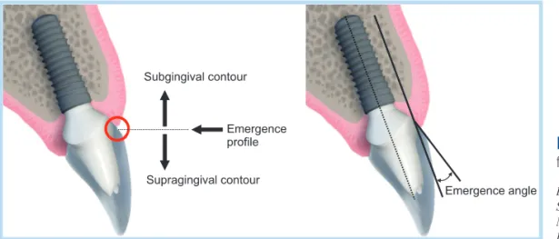
Emergence profile은 치은열구에서 자연치 또는 보철 물이 시작되는 형태를 의미하며 치은연하 형태에서 치은 연상 형태로 이행되는 형상을 일컫는 용어이고 치아의 장축이나 임플란트의 장축에 대해서 치은열구에서 나오 는 형태가 이루는 각도를 emergence angle이라고 한다 (Fig. 1)1,2.
보철물의 emergence profile을 자연치아의 형태와 유 사하게 형성하는 것은 심미성을 위해 필요하며 치태침착 과 음식물의 저류를 예방할 뿐만 아니라 구강 위생관리 를 쉽게 할 수 있어 보철물로 인한 치은염증을 감소시킨 다고 알려져 있다3,4.
I 서론
치치과진료에서 임플란트 치료가 차지하는 비중 이 커지면서 임플란트 고정체 디자인과 표면 의 발전과 더불어 상부구조물의 제작방법도 기공적인 기술과 더불어 눈부신 발전을 이루어 왔다. 초 기 임플란트 치료가 임플란트 고정체의 골유착에 중점을 두었다면, 근래에는 최종 임플란트 보철물의 심미적인 부분과 장기적인 기능유지 부분에 더욱 많은 관심이 집 중되고 있다. 이와 같은 심미적이고 기능적인 임플란트 보철을 위한 조건으로 상황에 맞는 적절한 abutment의 선택이 중요하다. 초기 Brånemark 임플란트에서 사용된 Standard abutment 이후 다양한 형태의 제품들이 시장 에 소개되어 왔고 특히 UCLA abutment를 사용한 환자 맞춤형 abutment는 많은 어려운 임상증례에 해결책으로 여겨져 왔다. 하지만 최근의 주 재료비인 금값과 부품비 의 상승과 더불어 생체적합성에서의 문제와 숙련된 기공 사의 도움이 필요하다는 단점들이 극복된 computer aided design/computer aided manufacturing (CAD/
CAM) 방식의 새로운 형태의 환자 맞춤형 abutment가 여 러 회사를 통해 소개되고 있다.
Fig. 1. Definition of emergence pro- file and emergence angle.
Ki-Seong Kim : Considerations in Using Patient- Specific Computer Aided Design/Computer Aided Manufacturing (CAD/CAM) Titanium Abutment.
Implantology 2013
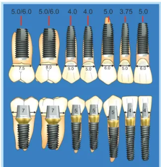
Croll1,2은 자연치아들의 분석 결과 대부분 emergence profile은 거의 직선형이었다고 보고하였고 따라서 치과 수복물의 목적이 상실된 치아를 정확히 재현, 복제하는 것이므로 치과 수복물들은 직선형의 emergence profile 을 가져야 한다고 주장하였다. 이상적으로 임플란트 보 철물 제작 시 자연치아의 형태와 유사한 emergence profile을 만드는 가장 쉬운 방법은 자연치 치경부와 비 슷한 직경의 임플란트를 심어 활용하는 것이다. 하지만 자연치아가 발치된 상태에서 남겨진 치조골과 치은조직 에 치근과 유사한 직경의 고정체를 사용하는 것은 실질 적으로 불가능하다. Emergence profile을 개선할 목적으 로 Branemark type의 external implant에서는 가능하면 치조골이 허용하는 한 구치부에서 굵은 직경의 임플란트 를 사용하는 것을 권장했었고 요사이 많이 사용되는 submerged 임플란트 타입의 internal type에서는 구치부 에 굵은 직경의 임플란트를 심어도 abutment가 시작되 는 connection의 직경이 같은 경우가 많기 때문에 고정체 는 깊게 심고 가능하면 abutment 수준에서 직경을 증가 시켜서 emergence profile을 자연치와 유사하게 만들고 자 시도해 왔다(Fig. 2).
임플란트 보철수복에 있어서 자연치아를 모방하고자 하 는 노력은 임플란트 자체 구조의 디자인에서부터 있어 왔 다. Holt 등5은 생물학적인 면을 고려한 포물선 모양의 플 랫폼을 갖는 임플란트 디자인을 선보였는데 이러한 형상 은 인접면 부위의 생물학적 폭경을 침범하지 않아서 골흡 수를 최소화하게 되므로 심미성이 요구되는 부위에서 심 미적인 치은 형태를 보존할 수 있다고 하였다(Fig. 3).
또한 Gallucci 등6은 137개의 발거된 치아들의 디지털 이미지들을 통해 자연치의 Cemento-enamel junction (CEJ)를 분석한 논문을 발표하였는데 심미적이고 생물학 적인 최적의 임플란트 보철물을 제작하기 위해서는 자연 치의 CEJ를 모방한 임플란트 플랫폼 디자인이 필요하다 고 주장하였다(Fig. 3).
이러한 제안들을 바탕으로 Nobel Biocare사에서는 2003년 scalloped 형상의 임플란트 플랫폼을 갖는 형태 의 Nobel Perfect (Nobel Biocare AB, Gothenburg, Sweden) 를 출시하였고, Astra 임플란트에서는 OsseoSpeed Profile implant (AstraTech AB, Mölndal, Sweden)를, 국 내에서는 Oneplant의 TaeGeukPlant (Oneplant Co, Seoul, Korea)라는 scalloped된 머리를 갖는 임플란트가 출시되었는데 임상적 관점에서의 성공여부는 좀 더 관망 해 볼 필요가 있어 보인다(Fig. 4).
자연치 형태의 모방한 결과 면에서 보면 임플란트 플 랫폼에서의 모방보다 지대주의 치은연하 부위와 emer- gence profile 부위에서의 모방이 더 효과적으로 보인다.
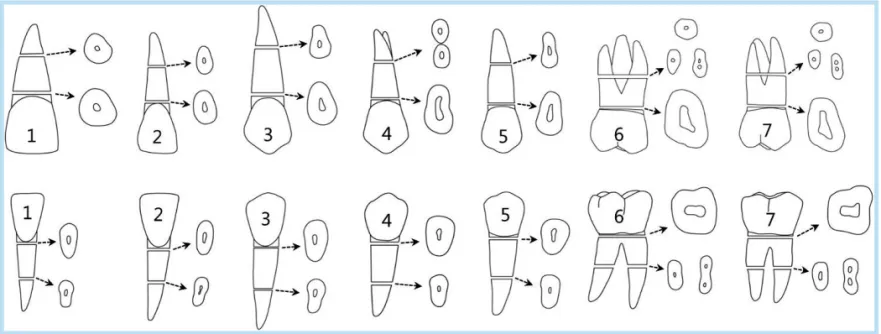
최근 널리 사용되기 시작한 CAD/CAM abutment는 자연 치의 치경부와 치근단면 형상이 원형이 아니라는 사실에 서부터 그 개념이 출발한다. 특히 소구치 부위에서는 치 경부에서 근원심 간 직경과 협설 간 폭경이 차이가 많이 나는 것을 볼 수 있고 이러한 큰 차이는 임플란트 보철물 의 emergence profile 형성 시 어려움을 준다(Fig. 5).
Fig. 2. Selection of fixture and abutment diameter considering natural tooth form.
Ki-Seong Kim : Considerations in Using Patient-Specific Computer Aided Design/
Computer Aided Manufacturing (CAD/CAM) Titanium Abutment. Implantology 2013
임상의들은 상실된 치아 부위에 원형의 임플란트를 식 립하며 그 위에 사용하는 기성 abutment는 또한 대개 원 형 형태의 디자인을 가지고 있다. 기성 abutment와 치근 단면 간의 형태 차이를 해결하는 방법으로서 CAD/CAM
customized abutment는 그 효용성을 갖는다고 할 수 있 다(Fig. 6).
CAD/CAM customized abutment는 기존의 UCLA abutment를 이용한 왁스업과 주조 방식의 개념에서 탈
Fig. 3. (A~C) Parabolic implant design by Holt. (D) CEJ profile analysis by Gallucci. In proximal views, v-p distance was defined as length between most vestibular and most palatal points of CEJ. The c distance was measured as length separating most incisal point of CEJ and v-p line (measured at right angle). Finally, ca distance was defined between most incisal point of CEJ and most apical edge of interproximal contact area. On buccal and proximal views, m-d distance was defined as length between most mesial and most distal points of CEJ. CEJ: cemento-enamel junction, μgap: microgap (implant-abutment junction), miCEJ: most incisal point of CEJ, CP: most apical point of interproximal contact surface.
Ki-Seong Kim : Considerations in Using Patient-Specific Computer Aided Design/Computer Aided Manufacturing (CAD/CAM) Titanium Abutment. Implantology 2013
Fig. 4. (A) Nobel Biocare Nobel- Perfect. (B) Astra OsseoSpeed Profile implant. (C) Oneplant TaeGeukPlant.
Ki-Seong Kim : Considerations in Using Patient- Specific Computer Aided Design/Computer Aided Manufacturing (CAD/CAM) Titanium Abutment.
Implantology 2013
피하여 CAD/CAM 응용 가공 기술을 이용하여 titanium 을 밀링하여 제작하는 시멘트 유지형 보철물을 위한 환 자 맞춤형 abutment이다.
특히 임플란트 식립 위치와 각도가 벗어난 경우와 심
미적 디자인이 요구되는 전치부 증례, 불규칙한 치은 형 상을 갖거나, 또는 너무 깊게 심겨진 증례의 보철물에 사 용되는 abutment이다. 많은 장점들이 있는 CAD/CAM abutment를 사용시에도 생각해야 할 주의점이 있다. 많 은 임상의들이 자연치아의 치근단 형태의 모방에만 치중 해서 심겨진 임플란트의 위치와 직경, 깊이 등에 상관없 이 치은 관통부의 abutment 모양을 너무 과하게 크게 제 Fig. 6. Computer aided design/computer aided man-
ufacturing (CAD/CAM) abutment and stock abutment over cross sectional view in cervix of natural tooth.
Ki-Seong Kim : Considerations in Using Patient-Specific Computer Aided Design/
Computer Aided Manufacturing (CAD/CAM) Titanium Abutment. Implantology 2013
Fig. 7. Computer aided design/computer aided man- ufacturing (CAD/CAM) abutment and stock abutment.
Ki-Seong Kim : Considerations in Using Patient-Specific Computer Aided Design/
Computer Aided Manufacturing (CAD/CAM) Titanium Abutment. Implantology 2013
Fig. 5. Natural tooth and cross sectional view (WOELFEL’S dental anatomy, it’s releveance to dentistry, 7th edition).
Ki-Seong Kim : Considerations in Using Patient-Specific Computer Aided Design/Computer Aided Manufacturing (CAD/CAM) Titanium Abutment. Implantology 2013
작하는 경향이 있다는 것이다. 이런 형태로 제작된 abutment는 경우에 따라서는 치은압박으로 인한 구강 내에서 Abutment 체결도 어려울 뿐 아니라 향후 반복되 는 임플란트 주위 치은염과 나아가서는 치조골의 흡수를 동반하는 peri-implantitis를 일으킬 수 있다.
Abutment의 구조는 connection 체결 부분, 치은 부분, 보철물 유지부분으로 나눌 수 있으며 여기서는 주로 치 은 부분에 국한해서 알아보고자 한다(Fig. 7).
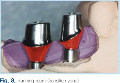
흔히 running room 또는 transition zone으로 불리는 치은 관통 부분은 임플란트 fixture top에서 gingival line 까지의 공간을 말한다(Fig. 8). 우리가 사용하는 CAD/
CAM customized abutment는 모든 문제점을 해결해 주 는 만능 해결사의 역할을 하는 것이 아닌 단지 도움이 되 는 보조적인 수단의 역할을 한다고 할 수 있다. 그래서 연조직을 술자가 원하는 치근단 단면의 형상으로 만들어 주기 위해서는 적절한 높이의 running room이 필요하 다. 즉 임플란트를 적절한 깊이로 심어서 fixture top에 서 gingival line까지 이어주는 치은부분에 적당한 두께 가 있어야만 soft tissue sculpting을 통해서 원하는 치근 단면 형상의 모양을 만들 수 있다7. 기성 abutment의 치 은 부분은 대부분 회전체 형상으로서 선반(lathe) 절삭 가공에 의해 일률적으로 제작되지만 CAD/CAM custom- ized abutment의 치은 부분은 비회전체 형상으로 밀링 (milling) 절삭 가공에 의해 처리되므로 술자의 의도에 따 라 자연치 치근의 형상을 재현할 수 있다는 장점이 있다.
Soft tissue sculpting은 soft tissue contouring 또는 soft tissue conditioning 등으로도 표현되며 술자가 주모 Fig. 8. Running room (transition zone).
Ki-Seong Kim : Considerations in Using Patient-Specific Computer Aided Design/
Computer Aided Manufacturing (CAD/CAM) Titanium Abutment. Implantology 2013
Fig. 9. Gull wing concept and contour guideline.
Ki-Seong Kim : Considerations in Using Patient- Specific Computer Aided Design/Computer Aided Manufacturing (CAD/CAM) Titanium Abutment.
Implantology 2013
형상에서 임의로 삭제, 조정한 artificial gum상에서 제 작된 abutment나 보철물에 의해 형성되기도 하고 구강 내에서는 healing abutment의 직경을 변화시키거나 임 시 수복물 등에 레진 등을 첨삭해서 형성할 수 있다.
자연치의 보철 수복 시 치경부의 emergence profile의 형태를 제작 시에는 Kay8가 주장한 Gull wing form을 이 용하거나 Contour guideline concept 등을 활용하는 등 다양한 기준점들이 Kibayashi9에 의해 언급된 바 있지만 implant 보철에서 emergence profile에 중요한 영향을 미
치는 치은 하방의 형태(subgingival contour)에 관한 정 보는 문헌상에서 제시된 바가 별로 없다(Fig. 9).
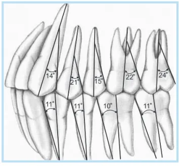
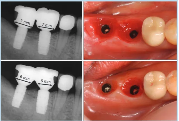
자연치 전치의 emergence 형태를 관찰한 결과 Wagman10 은 22.5도, Croll2은 15도, Yotnuengnit 등11은 약 11~16도 의 emergence angle을 갖고 있다고 보고하였고 구치부 도해도에서 살펴보아도 최대 24도 정도까지의 각도를 보 인다(Fig. 10). 자연치아에서의 emergence angle의 정의 (치경부 부위에서 emergence profile의 각도)와는 달리 2005년 발간된 8판 The glossary of prosthodontic term 에서는 emergence angle을 ‘the angle of the dental implants’ transitional contour as determined by the relation of the surface of the abutment to the long axis of the implant body’라고 정의하고 있다12. 자연치아와는 달리 임플란트 수복물의 형태를 주로 결정하는 부분이 치은연하의 abutment의 형태와 각도이므로 이 부분에 관한 기준점의 제시가 필요한 상황이다. Fig. 11은 internal submerged implant 고정체에 체결된 직경 6 mm의 abutment들의 gingival collar의 높이에 따른 emergence angle의 변화를 보여준다. 사용되는 collar의 높이가 커질수록 emergence angle은 줄어든다.
결손된 자연치를 임플란트로 수복하고자 할 때, 자연 치와 유사한 emergence profile을 재현하기 위해서는 해 당 자연치 CEJ 2 mm 하방의 치근직경에 가까운 임플란 Fig. 10. Emergence angle of natural tooth.
Ki-Seong Kim : Considerations in Using Patient-Specific Computer Aided Design/
Computer Aided Manufacturing (CAD/CAM) Titanium Abutment. Implantology 2013
Fig. 11. Emergence angle changes of impant abutment according to collar height.
Ki-Seong Kim : Considerations in Using Patient- Specific Computer Aided Design/Computer Aided Manufacturing (CAD/CAM) Titanium Abutment.
Implantology 2013
트의 직경을 선택하는 것이 필요하다. 상,하악 전치와 소 구치 영역에서는 이런 선택이 가능하지만 상,하악 대구 치의 평균 치근직경과 사용 가능한 임플란트의 직경 사 이에는 큰 차이가 있으므로 대구치 부위의 임플란트 보 철물에서는 필연적으로 emergence angle의 증가를 가져 오게 된다. 그렇다면 어느 정도까지의 emergence angle 의 abutment를 임상에서 사용하라고 그 기준을 정할 수 있을까?
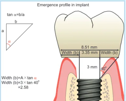
자연치 치근의 직경과 사용 가능한 임플란트 직경이 가 장 큰 차이를 보이는 하악 대구치의 경우를 예를 들어본 다(Fig. 12). 임플란트가 적절한 깊이로 심겨져서 gingi- val line에서부터 3 mm의 running room을 확보한 경우 이다. 삼각함수를 이용하여 계산해보면, 40도의 emer- gence angle을 가지는 경우 3 mm 치은깊이 대비한 쪽으 로의 수평확장의 폭은 2.58 mm (Width b)가 되며 최종 치경부에서의 폭경은 8.51 mm가 되는데 이 수치는 하악 자연치 대구치부의 치경부 직경에 해당한다. 즉 적절한 임플란트의 깊이조절에 따른 충분한 running room이 확 보된다면 40도 이상의 abutment emergence angle은 필 요치 않아 보인다. 물론 이 경우는 internal submerged 임플란트를 사용한 예이고 사용되는 임플란트의 con- nection 타입과 고정체의 직경과 식립깊이에 따라 필요 한 running room은 변하게 된다(Fig. 13).
임상적으로 허용될 수 있는 emergence profile의 한계 또는 이를 숫적으로 나타낼 수 있는 emergence angle의 임계각도(critical angle)를 과학적인 근거를 통해 제시하 기는 어렵다. Kim13은 이러한 임계각도는 인접치조골의 형태라는 변수에 영향을 받게 되며 발치 즉시 식립 또는 발치와의 치유가 완성되기 전에 조기 식립된 경우에는 많은 경우 인접 치조정(bony crest)에 비해 임플란트의 Fig. 12. Emergence profile of implant in molar region.
Ki-Seong Kim : Considerations in Using Patient-Specific Computer Aided Design/
Computer Aided Manufacturing (CAD/CAM) Titanium Abutment. Implantology 2013
Fig. 13. Running room in various implant systems.
Ki-Seong Kim : Considerations in Using Patient- Specific Computer Aided Design/Computer Aided Manufacturing (CAD/CAM) Titanium Abutment.
Implantology 2013
플랫폼이 더 하방에 위치하므로 emergence profile의 형 태는 더 수직에 가깝게 형성되어야 하는 반면 오랜 무치 악기간을 거쳐 편평해진 잔존치조제에 식립된 경우는 emergence angle을 조금 더 증가시킬 수 있는 여지가 있 을 수 있다고 하였다.
임플란트 보철물의 emergence profile을 결정하는 것 은 단순한 심미적인 기준으로 자연치 치경부와 같은 폭 으로 치간공극을 최대한 메우려고 해서는 안된다. 심미 적인 요구와 자연치아의 모방에 너무 집중하다 보면 임 플란트가 가져야 할 biologic width를 침범하게 되고 이 는 치은부종과 염증 및 골흡수를 동반하는 peri- implantitis를 일으킬 가능성을 높이므로 때로는 주어진 상황에 맞는 타협점을 모색해야만 한다. 즉 abutment의 emergence profile은 주변 경조직과 연조직의 형태가 허 용하는 생리적인 범위 내에서만 확장되야 한다(Fig. 14).
Abutment의 치은연하 형태를 디자인 시 고려해야 할 추가적인 요소는 abutment collar 부위의 형상이다. 임플 란트 고정체의 상단부에서 시작해서 abutment의 변연으 로 이어지는 형상은 볼록형(convex), 직선형, S-line형,
오목형(concave) 등 다양하게 디자인될 수 있다. 술자마 다 선호하는 형상의 차이가 있으므로 일률적으로 한 가 지 형상이 이상적이라고 할 수는 없지만 일반적으로 internal submerged implant를 사용할 경우, 골 하방으 로 약간 깊게 심는 것을 고려한다면 임플란트 고정체 상 단부를 출발해서 직상방 1 mm 정도는 오목한(concave) 형상을 갖는 것이 인접치조골과의 간섭을 피하고 연조직 의 양을 증가시켜 골흡수를 예방하는 효과가 있다14. Fig. 15. Various profiles of abutment collar.
Ki-Seong Kim : Considerations in Using Patient-Specific Computer Aided Design/
Computer Aided Manufacturing (CAD/CAM) Titanium Abutment. Implantology 2013
Fig. 14. Abutments with too-wide emergence angle have caused peri- implantitis (By courtesy of Sung Moo-Gyung).
Ki-Seong Kim : Considerations in Using Patient- Specific Computer Aided Design/Computer Aided Manufacturing (CAD/CAM) Titanium Abutment.
Implantology 2013
Abutment 변연 직하방에서 너무 급격한 경사로 폭이 줄 어들게 되면 약간의 치은 퇴축 시에도 undercut 정도가 심해져서 음식물 잔사가 축적되고 청소성이 떨어지게 될 수 있으므로 전체적으로는 약간의 S-line을 갖는 형태가 바람직하다(Figs. 15, 16).
임플란트 보철물의 변연은 심미적으로 문제가 되지 않 을 범위에서 가능한 치은연에 가깝게 위치해야 임플란트 주위염 예방에 유리하다. 임플란트 주위 연조직은 보철 물 주위 치은연 하방 1 mm까지는 자연치 치은열구상피
(sulcular epithelium)와 비슷하게 각화층을 유지하고 그 하방으로는 접합상피(junctional epithelium)와 유사한 비각화 상피, 그리고 결합조직으로 구성된다(Fig. 17)15. 임플란트 보철물이 장착된 이후 시간이 흐름에 따라 임 플란트 주위 치은 연조직에는 긴 비각화 상피지대가 형 성되며 이는 혐기성 세균 증식에 취약하다. 임플란트 주 위 연조직에는 혈관 구조가 적기 때문에 염증에 저항하 는 백혈구의 유주가 적고 반흔조직과 유사해서 저항성이
Fig. 16. S-line subgingival contour is better in deep implant position.
Ki-Seong Kim : Considerations in Using Patient- Specific Computer Aided Design/Computer Aided Manufacturing (CAD/CAM) Titanium Abutment.
Implantology 2013
Fig. 17. Soft tissue profile around internal submerged implant. Sulcular epithlium (SE), junctional epithelium (JE), connective tissue (CT) (By courtesy of Park Hwee-Woong).
Ki-Seong Kim : Considerations in Using Patient-Specific Computer Aided Design/
Computer Aided Manufacturing (CAD/CAM) Titanium Abutment. Implantology 2013
Fig. 18. Difference between round-shape healing abutments and individualized subgingival contour of computer aided design/computer aided manufacturing (CAD/CAM) abutment.
Ki-Seong Kim : Considerations in Using Patient-Specific Computer Aided Design/
Computer Aided Manufacturing (CAD/CAM) Titanium Abutment. Implantology 2013
낮은 조직이므로 자연치에 비해 세균의 침범에 방어하는 능력이 떨어지고 회복기전의 반응이 느리다16. 또한 깊어 진 보철물의 변연은 임플란트 주위 연조직의 생물학적
폭경(biologic width)을 침범하게 되어 원치 않는 치은 퇴 축이나 치조골 소실을 일으킬 수 있다. 따라서 구강위생 관리나 여분의 시멘트 제거, 세균의 증식 방지 등을 고려 Fig. 19. (A) Smart healing abutment of Osstem implant. (B) Smart impression coping of Osstem implant.
(C) Natural healing abutment and occlusal view images of Epros.
Ki-Seong Kim : Considerations in Using Patient- Specific Computer Aided Design/Computer Aided Manufacturing (CAD/CAM) Titanium Abutment.
Implantology 2013
Fig. 20. (A) Oval-shape subgingival contour made by Osstem Smart healing abutment. (B) Oval-shape subgingival contour made by Epros Natural abutment.
Ki-Seong Kim : Considerations in Using Patient- Specific Computer Aided Design/Computer Aided Manufacturing (CAD/CAM) Titanium Abutment.
Implantology 2013
하면 최종 임플란트 보철물의 변연은 각화층인 치은연 1 mm 이내에 설정하는 것이 바람직해 보인다.
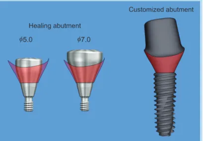
임플란트의 주위 치은은 healing abutment의 형태대 로 치유된다. 원형인 healing abutment에 의해 형성된 치은조직은 각 치아의 특징적인 치경부, 치근 형태가 재 현된 customized abutment를 장착 시 치은에 과도한 압 박이 가해질 가능성이 있다(Fig. 18). 이를 해결하기 위해 최근에는 healing abutment도 원형이 아닌 자연치아 경 부 단면 형태의 customized healing abutment들이 출시 되어 사용되고 있다(Figs. 19, 20). 가장 이상적으로는 healing abutment, impression coping, 그리고 customized abutment의 치은연하 형태가 모두 같은 형상으로 일치하 는 것이 좋지만 그러기에는 너무 많은 부속품들이 필요 하게 된다.
Healing abutment 외에도 temporary abutment에 구 강 내 경조직과 연조직의 상태에 따라 레진을 첨가해 주 거나 삭제해가면서 임시수복물을 제작해서 치은연하의 형태를 결정하고 심미적이면서 치태조절이 쉬운 보철물 의 emergence profile을 만들기 위한 치은 외형을 형성해 갈 수도 있다. 문제는 이러한 과정 등을 통해 형성된 치 은의 형태를 주모형상에 어떻게 재현해 내는가 하는 것 이다. 일반적인 경우 fixture level 인상채득을 위한 impression coping의 연결 및 방사선 사진을 통한 정체결 검증 등의 시간 동안 치은의 형태는 tissue support가 상
실되어 인상채득 직전에는 힘들게 형성해 놓은 치은의 형태가 무너져 버린다.
만들어 놓은 치은의 형태를 기공실에 전달하는 방법들 로는 다음과 같다.
1. 임시수복물의 형태를 복제하여 그 하부 형태를 impression coping에 레진을 덧붙여 individual impres- sion coping을 만들어 이용하는 방법17,18
2. 맞춤형으로 제작된 impression coping을 이용하는 방법
3. 임시수복물 자체를 impression coping으로 이용하 는 방법
4. 구강 내에서 치은선이 표시된 임시수복물을 주모형 에 체결한 후 연조직 대체재료를 주입하는 방법18
일차적으로 미리 soft tissue sculpting을 해 놓는 치은 의 형태를 복제, 재현해 나가는 것의 장점은 임의로 주모 형의 인공치은을 삭제하여 형성된 연조직의 형태를 통해 제작된 abutment를 구강 내에 체결할 경우 생기는 치은 압박에 따른 불편함과 주모형의 치은 형태와 구강 내 치 은의 3차원적 형태와 항상 같지는 않아서 생기는 변연 위 치의 변화 등을 예방할 수 있다는 것이다. 임의로 결정된 치은변연 위치에서 제작된 abutment를 이용할 경우에는 오랜 기간 동안 임시수복물을 통해 안정된 치은조직을 확보한 이후 최종보철물을 위한 인상채득과정에 들어가 야 한다(Fig. 21).
Fig. 21. Computer aided design/
computer aided manufacturing (CAD/
CAM) customized abutments and provisional restorations of maxillary anterior teeth.
Ki-Seong Kim : Considerations in Using Patient- Specific Computer Aided Design/Computer Aided Manufacturing (CAD/CAM) Titanium Abutment.
Implantology 2013
III 결론
CAD/CAM technology 발전은 customized abutment가 필요한 우리에게 새로운 대안을 제시해 주었다. 하지만 customized CAD/CAM abutment가 모든 문제를 해결해 주는 만능해결사가 아니라는 것도 생각해 두어야 한다.
Customized CAD/CAM abutment의 장점과 고려할 점 들, 그리고 주의점에 관한 지식을 갖고 잘 활용한다면, CAD/CAM abutment는 앞으로 보다 많은 임상증례에서 우리에게 도움이 되리라 본다.
참고문헌
1. Croll BM. Emergence profiles in natural tooth contour. Part I:
photographic observations. J Prosthet Dent. 1989; 62: 4-10.
2. Croll BM. Emergence profiles in natural tooth contour. Part II: clinical considerations. J Prosthet Dent. 1990; 63: 374-379.
3. Stein RS, Kuwata M. A dentist and a dental technologist analyze current ceramo-metal procedures. Dent Clin North Am. 1977; 21: 729-749.
4. Reeves WG. Restorative margin placement and periodontal health. J Prosthet Dent. 1991; 66: 733-736.
5. Holt RL, Rosenberg MM, Zinser PJ, et al. A concept for a biologically derived, parabolic implant design. Int J Periodontics Restorative Dent.
2002; 22: 473-481.
6. Gallucci GO, Belser UC, Bernard JP, et al. Modeling and characterization of the CEJ for optimization of esthetic implant design.
Int J Periodontics Restorative Dent. 2004; 24: 19-29.
7. Stein JM, Nevins M. The relationship of the guided gingival frame to the provisional crown for a single-implant restoration. Compend Contin Educ Dent. 1996; 17: 1175-1182.
8. Kay HB. Criteria for restorative contours in the altered periodontal environment. Int J Periodontics Restorative Dent. 1985; 5: 42-63.
9. Kibayashi H. The interface of restorations and periodontal tissue: the verification of the subgingival contour which can achieve tissue stability.
The Quintessence. 2012: 17: 63-83.
10. Wagman SS. The role of coronal contour in gingival health. J Prosthet Dent. 1977; 37: 280-287.
11. Yotnuengnit B, Yotnuengnit P, Laohapand P, et al. Emergence angles in natural anterior teeth: influence on periodontal status. Quintessence Int.
2008; 39: e126-133.
12. The glossary of prosthodontic terms. J Prosthet Dent. 2005; 94: 10-92.
13. Kim C, Determination of the emergence profile of custom abutment. J Korean Acad Esthetic Dent. 2012; 21: 61-69.
14. Touati B, Rompen E, Van Dooren E. A new concept for optimizing soft tissue integration. Pract Proced Aesthet Dent. 2005; 17: 711-2, 714-5.
15. Fradeani M, Barducci G. Esthetic rehabilitation in fixed prosthodontics.
Vol. II. Prosthetic treatment: a systematic approach to esthetic, biologic, and functional integration. London: Quintessence Publishing; 2008. p. 352.
16. Buser D, Weber HP, Donath K, et al. Soft tissue reactions to non- submerged unloaded titanium implants in beagle dogs. J Periodontol.
1992; 63: 225-235.
17. Fradeani M, Barducci G. Esthetic rehabilitation in fixed prosthodontics.
Vol. I. Esthetic analysis: a systematic approach to prosthetic treatment.
London: Quintessence; 2004. p. 304.
18. Alani A, Corson M. Soft tissue manipulation for single implant restorations. Br Dent J. 2011; 211: 411-416.