채널추정 오류를 고려한 MISO Pre-Rake TDD-CDMA 시스템의 성능
정인철* 정회원
Performance for MISO Pre-Rake TDD-CDMA system with Channel Estimation Error
Incheol Jeong* Regular Member
요 약
복수의 안테나를 사용하는 Pre-Rake CDMA 시스템은 복잡한 RAKE 합성기를 수신기에서 사용하지 않아도 좋은 수신 성능을 얻을 수 있는 장점이 있다. 그러나 Pre-Rake 시스템은 채널 추정오류에 크게 영향을 받기 때문에 시스템 성능 평가에 있어서 채널추정 오류는 반드시 고려되어야 한다고 볼 수 있다. 본 논문에서는 채널추정오류를 가지는 MISO Pre-Rake CDMA 시스템을 이론적인 해석을 통하여 분석한 후 도출된 결과를 컴퓨터 시뮬레이션을 이용해 얻은 결과와 비교한다. 이론적인 해석결과로 볼 때, Pre-Rake 시스템의 성능은 진폭오류 보다는 위상오류에 의한 영향을 크게 받는 것으로 확인되었다.
Key Words : Pre-Rake, Channel estimation error, MISO, Multipath fading, CDMA, TDD
ABSTRACT
Pre-Rake CDMA system using multiple transmit antenna provides a good system performance without equipping a complicated RAKE combiner at the mobile receiver. However, the performance of the Pre-Rake systems are significantly affected by channel estimation error so that the effect of the channel estimation error should be considered and analyzed for evaluating the system performance. In this paper, MISO(Multi-Input Multi-output) Pre-Rake CDMA system with channel estimation error is analyzed by numerical analysis and the results are compared with that of the computer simulation. From the numerical results, it is found that the performance of the Pre-Rake system is more affected by the phase error than the amplitude error.
※본 논문의 일부는 국제학회 WPMC09에서 발표되었습니다.
*성공회대학교 정보통신공학과([email protected])
접수일자 : 2017년 5월 31일, 수정완료일자 : 2017년 6월 19일, 최종게재확정일자 : 2017년 6월 30일
I. Introduction
In mobile communication system diversity techniques are often used to improve the system performance in a fading channel. As a transmit diversity, Pre-Rake Diversity can be utilized at the base station (BS) to reduce the complexity of the mobile unit. The Pre-Rake combining method has been firstly proposed in [1] and several transmit diversity techniques for TDD-CDMA (Time Division Duplex-Code Division Multiple Access) systems have been proposed in [2][3]. Pre-Rake diversity is used not only in CDMA system but also in UWB (Ultra
Wide Band) systems. The Pre-Rake scheme for UWB communication systems are shown in [4][6][7]. An experimental result for Pre-Rake combiner using UWB-IR (Impulse Radio) has been also shown in [8].
In [2] two Pre-Rake transmit diversity schemes which utilize both path and space diversity have been proposed for TDD-CDMA. The transmit diversity system 2 which uses all antennas for Pre-Rake combining (MISO-Pre-Rake system) has been analyzed for multi-user condition in [5] and then it has been found that the system 2 outperformed system 1, which transmits a signal by using one selected antenna, in multi-user
environment.
On the other hand, channel estimation is an important factor for Pre-Rake systems since it affects a system performance significantly. For single antenna system the performance of Pre-Rake CDMA under imperfect channel estimation has been studied in [9]. However, Pre-Rake CDMA with channel estimation error has not been studied for multi-antenna system. Therefore, in this paper, we analyze the system performance for multi-antenna Pre-Rake system with channel estimation error by using numerical analysis and computer simulation. The numerical results are also compared with that of the computer simulation.
This paper is organized as follows. Channel model and channel estimation error model is described in section Ⅱ and Pre-Rake CDMA with channel estimation error is analyzed by numerical analysis in section Ⅲ. The BER performances obtained by numerical analysis and computer simulation are shown in section Ⅳ. Finally, conclusion is given in section Ⅴ.
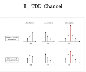
Ⅱ. TDD Channel
Fig. 1. Pre-Rake Combining Process
Fig. 2. Channel Estimation Error Model
1. Channel Model
We utilize the simplified tapped delay line multipath channel model of [10]. The reverse channels are assumed to be statistically independent for all users. Also with the utilization of reverse link power control, we assume that all channels are statistically identical, even if the mobile units are at different distances from the BS. The complex low-pass impulse response of the channel for antenna of user is given by
(1) where is the number of channel paths, the path gains are independent identically distributed (i.i.d.) Rayleigh random variables (r.v.'s) for all , and , the angle are i.i.d. uniformly distributed in and the is the PN code chip duration. Without loss of generality, we can take the normalization
2. Channel Estimation Error
In the TDD systems the channel is estimated by BS during the uplink period and the estimated signal is used for Pre-Rake combining in the downlink. The Pre-Rake combining process is shown in Fig.1. In case of perfect channel estimation the received signal shows perfect MRC diversity combining result but in case of imperfect channel estimation with channel estimation error the received signal does not show perfect combining result any longer.
Even though the channel estimation is perfectly performed in the BS, the error in channel estimation is found in the MS (mobile station) since the mobile channel is always time variant and the channel estimation error is depend on how fast the channel changes.
The channel changes can be measured by Doppler frequency and the time interval between up and downlink.
In this paper, we consider the error model of channel estimation in [9] and show the model in Fig.2. If the channel estimation error is considered, the estimate of the complex paths gain is given by
(2) where is a real r.v.'s, a log normal function [11] with a 0-dB mean and variation , and is treated as Gaussian r.v.'s with 0 mean and variance
.
Ⅲ. MISO Pre-Rake CDMA
Fig.3 shows the transmitter model for MISO Pre-Rake CDMA using multi-antenna. The system consists of M multiple antennas and the same number of Pre-Rake combiners at the BS. In the forward link, all the antennas are used to transmit the signal. At the pre-rake combiner, the pre-rake taps are weighted for each antenna by using the parameters which is estimated in the previous uplink time slot. The outputs of the pre-rake combiners are transmitted by the corresponding antenna. For each user, the transmit power is always kept to be equal.
Fig. 3. Base Station with MISO Pre-Rake Combiner
The downlink transmitted signal for user k can be represented by
⋅
(3)
where P is the transmitted power, is the carrier frequency, is the differentially encoded data stream for user k consisting of a train of i.i.d data bits with duration T which take the values of ± with equal probability. The current bit is denoted by while next or previous bits are denoted by adding or subtracting the superscripts by 1. is the spreading code of user with ±1 chips of duration and code length
.
The normalizing factor in Eq.(3) that keeps the instantaneous transmitted power constant is given by
. (4) In downlink, there exists channel estimation error in MS receiver so that the Eq.(3) will turn to be
⋅
(5)
where
. (6) Assuming a CDMA system with K users, the received signal at user 1 in downlink is given by
⋅
(7) where is the zero mean AWGN (Additive white Gaussian noise) with two sided power spectral density
. From Eq.(7), we can see that channel output includes
paths with a strong peak due to at a delay equivalent to and only one MF(Matched Filter) is needed to tune to this path. The output of user 1 MF is given by
(8) where is the self interference due to multipath, is the multiple access interference, and is a zero mean Gaussian r.v. with variance
. is the desired part for the current bit given by the part of and
in Eq.(8). After some manipulations is given by
(9)
where
Using Gaussian approximation we treat and as Gaussian r.v.'s. It is readily shown that and have zero mean, hence, we are only interested in their variances.
1. Self Interference
This interference exists in a single user system and is caused by multipath. From Eqs.(5)-(8), is found by putting and ≠ . can be written by
≠
⋅
⋅
(10)
where
≥ (11) In Eq(11), is the discrete aperiodic cross-correlation function defined in [12]. Denoting
by and utilizing
we can get
⋅
⋅
(12) Taking the second moment of Eq.(12) we can get
(13) where
2. Multiple Access Interference
The multiple access interference A due to other users is found by the part of in Eq.(8). After some manipulation, the interference is given by
⋅
⋅
(14)
Eq.(14) can be divided into two parts. They are given by
(15)
≠
⋅
⋅
⋅
(16)
If we use orthogonal codes such as Walsh-Hadamard codes in this system, the second moment of Eq.(15) and Eq.(16) is given by
⋅
(17)
where Q is given by for all by
⋯ ⋯
(18)
We can find this by noting that are i.i.d., and
for all and . From the definition in Eq.(6), we can find that
. (19)After some manipulations, Eq.17 is found to be
(20) Assuming in Eq.(8) as Gaussian r.v., we can find that the probability of error for BPSK, conditioned on
⋯ ⋯
is given by
. (20) In Eq.(20) is the signal to noise ratio given by
, where is the variance of the r.v.
. After some manipulation, is given by
⋅
(21) where
is th average received signal to noise
ratio. The probability of error, is evaluated from Eqs.
(20) and (21) using the Monte-Carlo method.
Ⅳ. BER Results
In order to evaluate the system performance, numerical analysis as well as computer simulations are utilized and compared with each other. For numerical analysis, the BER is evaluated by using Monte Carlo method [13]. At each iteration, × Rayleigh r.v.'s for , × Rayleigh r.v.'s for , and × Gaussian r.v.'s for
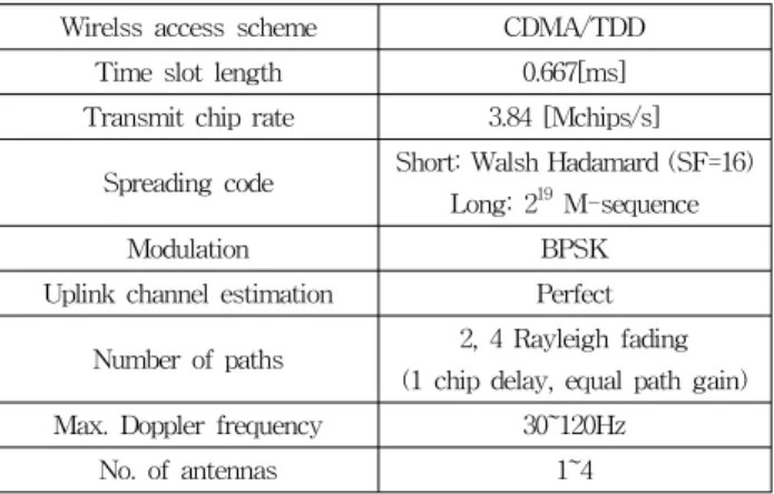
are computer generated. Then, is found and substituted in Eq.20. For each value, Eq.20 is averaged over a sufficiently large number of iterations. For computer simulation, the parameters in Table 1 are utilized. The time slot and the burst structures for 3GPP TD-CDMA system are used for the computer simulation.
In this simulation, a long spreading code with long is also used for the Pre-Rake system. The BER results of the computer simulation are compared with that of the numerical analysis.
Wirelss access scheme CDMA/TDD Time slot length 0.667[ms]
Transmit chip rate 3.84 [Mchips/s]
Spreading code Short: Walsh Hadamard (SF=16) Long: 219 M-sequence
Modulation BPSK
Uplink channel estimation Perfect
Number of paths 2, 4 Rayleigh fading (1 chip delay, equal path gain) Max. Doppler frequency 30~120Hz
No. of antennas 1~4
Table. 1 Simulation Parameters
1. Parameters for Channel Estimation Error
To compare the simulation results to that of the numerical analysis, the parameters including the amplitude error and the phase error should be examined. The amplitude error can be written as
In this paper, the prediction method was not used for downlink channel estimation. If there is no error in channel estimation, the amplitude error and the phase error will be and , respectively. Fig.4 shows an example of PDF (probability density function) for obtained by computer simulation under the condition of
, 3 time slot up/downlink interval, and 10000 samples simulated. From the figure we can find that the
amplitude error shows log-normal distribution. Therefore,
should be treated as a real r.v.'s with log-normal distribution. Fig.5 shows an example of PDF of obtained by computer simulation under the condition of
, 3 time slot up/downlink interval, and 10000 samples simulated. In this figure, it is noticed that the distribution of phase error is not uniform but Gaussian.
Fig.6 show the BER versus Maximum Doppler frequency for the case of 4 time slots (1antenna, 4 paths, 1user), where the BER performance degrade as the Maximum Doppler frequency increases. This is because the amplitude error and phase error increase as the Maximum Doppler frequency increases. The variances of
and which is related to amplitude and phase errors are shown in Fig.7 and Fig.8 for varying Maximum Doppler frequencies.
Fig. 4. Example of PDF for measured at the MS (Simulation)
Fig. 5. Example of PDF for measured at the MS (Simulation)
Fig. 6. BER vs. Maximum Doppler frequency
Fig. 7. [dB] vs. Maximum Doppler frequency
Fig. 8. vs. Maximum Doppler frequency
2. Comparison of Simulation Result and Analysis Result
For the Pre-Rake system with 1 antenna and single user, computer simulation is carried out and the BER performance is compared with that of the numerical analysis. Fig.9 shows the BER performance for the case of 4 paths and different maximum Doppler frequency (). In the figure, 4 time slots means the number of the downlink time slots. Even though multiple time slots are allocated to the downlink transmission, the downlink time slot used for BER performance evaluation is located at the 4th time slot from the uplink time slot so that the time interval between the up and downlink becomes 3 time slots. As shown in the figure it is noticed that the simulation results agree well with that of the numerical analysis. Fig10. shows the
Fig. 9. BER performance for 4 paths (1 antenna, 1 user)
Fig. 11. BER Performance for various number of antennas
BER performance of multiuser for 2 antennas in the case of low Maximum Doppler frequency ( , 1 time slot). Fig.11 shows the BER performance of 4 users for various number of antennas. From the figure it is shown that as the number of antennas increases the BER performance improves even if the channel estimation error exists.
3. Multi-Antenna and Multi-User
Fig.12 shows the BER performance for amplitude error.
This is the numerical analysis results for 4 users, 4 paths,
and . As shown in the figure, up to 10[dB] the BER performance degrade gradually. Under the condition for amplitude error it is noticed that the effect of
Fig. 12 BER performance vs. [dB] ( )
Fig. 13. BER performance vs. ( [dB])
antenna diversity is large enough. Fig.13 shows the BER performance for phase error. This result is the numerical analysis one for 4 users, 4 paths, and
. As contrast with amplitude error the BER performance degrade rapidly as the phase error increases.
It is also found that the BER performance can be improved by using antenna diversity for the case of phase error.
Ⅳ. Conclusion
The MISO-Pre-Rake CDMA with channel estimation error has been analyzed for multi-user environment. The phase error model based on Gaussian distribution has been introduced to the numerical analysis from the result of computer simulation, which is similar to realistic channel condition. The BER performances have been evaluated by theoretical analysis and compared to that of the computer simulation. From the results, it is found that the performance of the Pre-Rake system is more severely affected by the phase error than the amplitude error. Even though the Pre-Rake system is affected by the phase and the amplitude errors, the BER performances have been greatly improved by using the antenna diversity.
References
[1] R. Esmailzadeh and M. Nakagawa, “Pre-Rake diversity combining in time-division duplex CDMA mobile communications,” IEEE Trans. Veh. Technol., vol.48, no.3,
pp.795-801, May 1999.
[2] I. Jeong and M. Nakagawa, “A Novel transmission diversity system in TDD-CDMA,” IEICE Trans. commun., vol.
E81-B, no. 7, pp1409-1416, July 1998.
[3] I. Jeong and M. Nakagawa, “A Time Division Duplex CDMA System Using Asymmetric Modulation Scheme in Duplex Channel,” IEICE Trans. Commun., vol. E82-B, no. 12, pp.1956-1963, Dec. 1999.
[4] K. Usuda, H. Zhang, and M. Nakagawa, “Pre-Rake performance for pulse based UWB system in a standarzed short-rang channel,” in Proc. IEEE WCNC'2004, vol.2, pp920.925, Mar. 21-25, Atlanta, Georgia USA, 2004.
[5] I. Jeong and M. Nakagawa, “Forward link performance of TDD-CDMA with trasmit diversity scheme,” IEEE 3GWireless'2001, pp291-295, May 30-June 2, San Francisco, USA, 2001.
[6] E. Torabi, J, Mietzner, and R. Schober, “Pre-Equalization for Pre-Rake MISO DS-UWB Systems,” IEEE ICC'2008, pp4861-4866, May 19-23, Beijing, China, 2008.
[7] Z. Ahmadian, L. Lampe, ‘Robust Design of Widely Linear Pre-Equalization Filters for Pre-Rake UWB Systems’, IEEE Trans. Commun., vol. 61, no.10, Oct. 2013.
[8] R. Nakamura, H. Ishikawa, and A. Kajiwara, “Performance of Pre-Rake diversity combining in UWB-IR communications”, ICSPCS 2012, Gold Coast, QLD, Australia, 12-14 Dec. 2012.
[9] N. B. Harum, Y. Tamura, S. P. W. Jarot, R. Esmailzadeh, and M. Nakagawa, “Analysis of performance degradation due to channel estimation error in Pre-Rake TDD/CDMA,”IEICE Trans. Commun.,
vol.E88-B, no.6, pp.2508-2515, June 2005.
[10] J. G. Proakis, Digital Communications, 3rd Ed., New York:
McGraw-Hill, 1995.
[11] E. Kudoh, “On the capacity of DS/CDMA cellular mobile radios under imperfect transmitter power control,”IEICE Trans. Commun., vol.E76-B, no.8, pp.886-893, Aug. 1993.
[12] M. Pursley, "Performance Evaluation for Phase-Coded Spread-Spectrum Multiple-Access Communication-Part I:
System analysis," IEEE Trans. Commun., vol. COM-25, no.
8, August. 1977.
[13] W. H. Press, B. P. Flannery, S. A. Teukolsky and W. T.
Vetterlink, Numerical Recipes the art of scientific computing, New york: Cambridge university press. 1986.
저자
정 인 철(Incheol Jeong) 정회원
․2000년 3월:Keio Univ. 전기공학 공학박사
․2002년 2월:한국전자통신연구원 선 임연구원
․2002년 3월∼현재:성공회대학교 정 보통신공학과 교수
<관심분야> : 무선통신, 근거리통신, 가시광통신
![Fig. 7. [dB] vs. Maximum Doppler frequency](https://thumb-ap.123doks.com/thumbv2/123dokinfo/5034876.553292/6.892.482.792.471.778/fig-db-vs-maximum-doppler-frequency.webp)
![Fig. 12 BER performance vs. [dB] ( )](https://thumb-ap.123doks.com/thumbv2/123dokinfo/5034876.553292/7.892.105.413.123.427/fig-ber-performance-vs-db.webp)
