1. 서 론
( , STS 301L, STS 304L )
(press)
.(1) , (stress concentration source)
(heat input)
(fatigue strength)
Corresponding Author, [email protected]
(fatigue crack) .
,
. ,
·
.(2) ,
- (
P
-Nf) ,,
필렛 용접이음재의 피로설계에 관한 연구 STS 301L
백 승 엽*
A Study on Fatigue Design of STS301L Fillet Welded Joint
Seung yeb Baek*
* Dept. of Automobile Engineering Seoil Univ.
(Received October 26, 2009 ; Received February 24, 2010 ; Accepted March 11, 2010)
Key Words: Tensile strength(인장강도), Yield Strength(항복강도), Gas Welding(가스용접), Weld- Ment (용접부), Stress Concentration(응력집중), Fatigue Strength(피로강도)
초록 : 용접부는 일반적으로 잘 알려져 있는 바와 같이 외력에 의한 응력 집중원, (stress concentration source) 이 되는 것은 물론 용접과정에서의 입열(heat input)로 인한 성분과 조직의 변화에 의해 반복하중에 대한 피로 강도(fatigue strength)가 모재의 그것에 비해 훨씬 떨어져서 피로균열(fatigue crack)의 발단이 되고 있다 따라. 서 본 연구에서는 실제로 철도차량에 적용되는 가스용접 이음재 가운데 대표적인 형상시편들을 재질별로 피, 로실험을 수행하여 피로하중범위 피로수명- ( P-Nf) 관계를 도출하여 비교 평가하였다 또한 수치 해석적 유한· . , 요소법을 이용하여 용접이음재의 응력분포를 해석한 후 용접이음부에 발생하는 최대주응력으로, ( P-Nf) 관계 를 σ-Nf 관계로 재정리하였다 이상의 결과들을 바탕으로 가스용접이 적용된 철도차량 차체의 경제적이고. , 합리적인 피로설계를 위한 기초정보로 사용하고자 하였다.
Abstract: Stainless steel sheets are widely used as structural materials for the manufacture of railroad cars and commercial vehicles. These kinds structures used stainless steel sheets are commonly fabricated by using the gas welding. For the fatigue design of gas welded joints such as fillet joints and plug joints, it is necessary to obtain information on the stress distribution at the weldment and the fatigue strength of the gas welded joints. Moreover the influence of the geometrical parameters corresponding to the gas welded joints on the stress distribution and fatigue strength must be evaluated. P-Nf curves were obtained from the data recorded in fatigue tests. Using these results, the P-Nf curves were rearranged according the relation between σ-Nf and the maximum stress at the edge of the fillet welded joint.
.(3)
- (
P
-Nf) ,,
P
-Nf σ-Nf ·.
.
필렛용접 이음재의 변형과 응력분포에 2.
대한 유한요소 해석
해석 모델 2.1
Table 1 Chemical composition of material Material ; STS 301L
C Si Mn P S Ni Cr N
0.03 1.00 2.00 0.04 0.03 6~8 16~18 0.2
Fig. 1 Simulated model of the fillet gas welded joint
Fig. 2 3-D FEA model of fillet welded joint for stress analysis
Fig. 1 (simulation model) . Fig. 2
(fillet welded joint)
Table 2 Mechanical properties of materials
Material Symbol
Yeild strength
(MPa)
Tensile strength (MPa)
Elongation (%)
STS 301L
LT 215.6 548.8 44
DLT 343 686 39
ST 411.6 754.6 34
HT 686 931 19
(LT : Low Tensile, DLT : Deadlite Tensile, ST : Special Tensile, HT : High Tensile)
Table 3 Fillet type gas welding condition
Table 4 Maximum tensile strength of the various fillet welded joints
Welded joint type (plate thickness)
Max tensile strength N (kgf)
Fillet
ST(3.0)+ST(3.0) 27371 (2793) ST(1.5)+ST(1.5) 12985 (1325) HT(4.5)+LT(4.0) 33163 (3384) HT(4.5)+ST(4.0) 33310 (3399) ST(1.5)+HT(1.5) 14308 (1460) ST(4.0)+LT(2.5) 32134 (3279) ST(1.5)+DLT(1.5) 11652 (1189) ST(2.0)+DLT(2.0) 18581 (1894) DLT(2.0)+DLT(2.0) 43385 (4427) LT(4.0)+LT(4.0) 34241 (3494) combination of the specimen : Base metal(thickness) + Joining metal(thickness)
.(4,5)
STS
301L ,
Table 2 4 (LT:Low
Tensile, DLT:Deadlite Tensile, ST:Special Tensile,
HT:High Tensile) , 4
,
Table 1, 2와 같다 그리고. ,
(Young's modulus) ,
(6) (hardness)
(strength)
(7)
(ST:18,966 kg/mm2) (HT:21,516
kg/mm2) , 0.3
.
해석에 사용된 요소(element)는 3차원 육면체 요 소인 C3D8I를 적용하였으며 요소 수 및 절점 수는,
개의 요소와 개의 절점으로 구성하였
12,336 , 14,909
다 국부적인 용접부 메쉬 크기. (mesh size)는 1mm로 하였으며 경계조건, (boundary condition)은 Fig. 2에 표시된 조건으로 설정하였다 모델링과 탄 소성 해. ∙ 석은 상용프로그램인 I-DEAS 11nx와 ABAQUS 6.7 을 사용하였다.
2.2 해석결과
두께가 다른 판재를 접합한 경우와 같은 두께 를 접합한 경우 모두 다 인장재의 용접비드 단, 에서 응력집중이 일어나는 것을 (weld bead edge)
알 수 있었다 전체적으로 판 두께가 두꺼워지면. 판의 강성(rigidity)이 증가하여 변형과 최대응력 값은 감소하는 경향을 나타내었다.
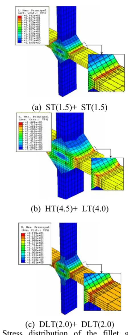
Fig. 3의 예는 STS 301L의 (a)ST(1.5)+ST(1.5), (b)HT(4.5)+LT(4.0), (c)DLT(2.0)+DLT(2.0)의 형태로 필렛 용접한 이음재의 형상을 모델링 한 후 인장하 중을 가했을 때 용접부 주변의 응력분포, 를 나타낸
(a) ST(1.5)+ ST(1.5)
(b) HT(4.5)+ LT(4.0)
(c) DLT(2.0)+ DLT(2.0)
Fig. 3 Stress distribution of the fillet gas welded joint subjected to tensile load
것이다 최대 주응력은 모두 용접부 토우. (weld toe) 와 열영향부 경계부에서 발생함을 알 수 있다 또. 한 동일한 두께에 기계적 성질이 상이한 필렛 용접, 시편에 인장하중을 가했을 때 용접부 주변의 최대, 응력 값은 ST(1.5)+ST(1.5)가 1,388 MPa,
는 는
ST(1.5)+HT(1.5) 1,184 MPa, ST(1.5)+DLT(1.5) 으로 나타났다 판재의 두께에 관계없이
1,787 MPa .
인장력에 의해 발생되는 최대응력은 Fig. 3의 결과 와 마찬가지로 용접비드 단에서 발생됨을 확인할 수 있었다 응력집중 발생위치는 재질과 판 두께에. 관계없이 시편의 부하 측 용접비드 단으로 일치하 나 재질 기하학적 형상에 따라 각각의 변형형태와, , 최대응력 값은 상이함을 알 수 있었다 최대응력 값. 은 ST(1.5)+DLT(1.5)의 재료조합이 가장 크게 나타 났다 이유는. Table 2의 기계적 성질에서 알 수 있 듯이 LT 및 DLT의 인장강도 및 항복강도가 ST 와 HT에 비해 상대적으로 낮기 때문이다. 즉 인장하,
중에 의한 DLT 판재의 변형이 ST와 HT에 비해 상 대적으로 커서 용접부 비드 단에서의 응력집중이 커졌기 때문인 것으로 판단된다. 이러한 해석결 과는 실제 피로시험 중 Photo 1에서와 같이 열향 부 경계부에서 응력집중현상이 발생되어 동일한 부분에 파단이 일어남을 확인할 수 있었다.
3. 가스용접 이음재의 피로강도평가 실험
3.1 시험편 및 실험장치
피로시험편은 Table 1, 2의 STS 301L 재료를 Fig. 1과 같은 형상으로 동종재 및 이종재간 가스
Photo 1 Failure location appeared on the fillet gas welded joint
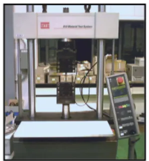
Photo 2 Hydraulic fatigue test machine(MTS, 10ton)
Fig. 4 ⊿P-Nf relation of various fillet gas welded joints
용접한 이음재로서, 용접성 평가를 통하여 도출 된 최적의 용접조건인 Table 3과 같은 용접조건 으로 제작하였다. 피로실험 장치는 Photo 2와 같 이 서보 유압식 피로시험기(MTS, 용량:10 ton)를 사용하였고, 시편을 고정시키는 면압식 지그(Jig) 는 자체 설계하여 제작하였다.
3.2 실험조건 및 실험방법
본 연구에서는 하중주파수 25 Hz인 일정진폭하 중을 시험편에 가하고, 부하형태는 하중비(R=
Pmin/Pmax)가 0 (Pmin=0)인 정현파(Sine wave)로 하였 다 무한수명의 피로한도를 구하기 위해서 시편. 의 종류별로 Table 4의 최대인장강도(maximum
의 에서 씩 하중을 감소시
tensile strength) 90% 10%
키면서 JIS Z 2273 및 JIS Z 3103에 의거 107 에 이를 때까지 피로시험을 수행하였다 그
cycles .
리고 각 시편의 피로수명(fatigue life)은 시편이 완전히 파단 되었을 때의 하중 반복수로 하였다.
실험 결과 및 고찰 3.3
은 의 동종재 및 이종재간 가스
Fig. 4 STS 301L
용접한 필렛용접 이음재의 피로강도를 ⊿P-Nf 선 도로 나타낸 것이다. Fig. 4로부터 각 용접 이음 재의 피로강도에 대한 기하학적 인자의 영향을 비교할 수는 있지만 앞에서 언급한 바와 같이, 용접과정에서 야기되는 용접금속의 야금학적 변 화 등이 기하학적 인자인 이음형상 재질 및 두, 께 등을 종합적으로 고려한 피로설계기준(fatigue 을 결정하는데 지장을 줄 만큼 데 design criterion)
Fig. 5 ⊿σ-Nf relation of various fillet gas welded joints
때문에 합리적인 설계기준을 설정하기 매우 어려 울 뿐만 아니라 설정된 설계기준의 신뢰성 문제, 도 제기될 수 있다 그리고 본 실험결과에서 고. , 려하지 않은 임의의 특정 이음형상에 대한 설계 데이터가 필요한 경우 추가적인 피로시험을 필, 요로 하기 때문에 이를 위해서는 많은 시간과 경 제적 추가비용이 들 수밖에 없다 따라서 피로수. , 명 데이터를 이용하여 설계기준을 설정함에 있어 서 2절의 응력분포 해석결과를 바탕으로 최대주 응력은 용접 지단부를 포함한 용접 열영향부에서 발생하고 있음을 실험적 해석적 방법으로 확인할· 수 있었기 때문에 피로균열이 발생 및 성장하는 위치의 최대주응력으로 피로강도를 평가하는 것 이 타당하다고 판단할 수 있었다. N. Tomioka,(8) Nam(9) 등은 용접부 주변의 외표면에서 측정된 응력분포 형태는 너깃 단의 열영향부에서 최대응 력이 발생한다고 밝혔다.
본 연구의 용접부에 대한 실험해석과 수치해석 공히 이들의 연구결과와 유사한 경향을 보이고 있음을 알 수 있다. ⊿P-Nf 관계의 결과와 응력분 포 해석결과를 가지고 응력진폭과 수명과의 관계 (⊿σ-Nf)를 도출하여 피로데이터를 재정리 한 결 과, Fig. 5의 결과를 얻을 수 있었다. 피로데이터 의 분산이 Fig. 4의 결과보다 상당히 줄어든 것을 확인할 수 있었다 이 결과로부터 필렛 가스용접. 이음재의 기하학적 인자를 종합적으로 고려한 피 로설계기준을 정할 수 있었으며, 약 100~300 정도로 평가되었다 이 결과는 여러 가지 기
MPa .
하학적 형상과 재질을 갖는 필렛 용접 이음재에 대한 피로설계는 피로균열이 발생 및 성장하는 위치의 최대주응력으로 피로강도를 평가하는 것 이 피로설계기준을 정할 때 보다 효과적인 설계 가 가능할 것으로 판단된다.
4. 결 론
용접구조물의 장 수명 피로설계기준을 확립하 기 위해서 본 연구에서는 필렛 가스 용접구조물 의 여러 가지 기하학적 형상을 갖는 용접이음재 의 응력분포를 해석하고 최대주응력에 대한 기하
과를 얻었다.
필렛 용접 이음재에 인장하중이 (1) STS 301L
작용하는 경우 용접부 최대주응력은 부하 측의, 용접비드 단과 열영향부 경계부에서 발생하였으 며 피로한도범위는, ⊿σ-Nf 관계를 기준으로 약
정도로 평가되었다
200~300 MPa .
피로강도 데이터를
(2) ⊿P-Nf 관계로 나타내
면 기하학적 인자와 기계적 성질의 영향에 대해, 상대적인 비교 평가는 가능하지만 피로설계기준· , 을 결정하기에는 데이터 분산 폭이 너무 크기 때 문에 피로균열이 발생 및 성장 파단에 이르게, 하는 최대주응력으로 하는 것이 합리적이다.
참고문헌
(1) Kang, H. T., 2005, "Fatigue Damage Parameter of Spot Welded Joints Under Proportional Loading,"
IJAT, 13, pp. 285~291.
(2) Bosh, "Automotive Handbook," pp.320~350.
(3) Sohn, I, S., Bae, D. H. and Jung, W. S., 1997,
"Fatigue Strength Evaluation of In-Plane Bending Type Spot Welded Lap Joint Using S. I. F. K.," KSME, Vol.1, No.1, pp. 24~28.
(4) Kang, J. B., 2003, "Fatigue Strength of the TS-Type Spot-welded Lap Joint of STS301L," Thesis of Master, Sungkyunkwan University.
(5) JSAE 1991, "Automatic Technology Handbook- Experimental Assessment," pp.81~105..
(6) Bae, D. H., 1990, "Fracture Mechanical Fatigue Strength Evaluation of A Strength Spot Welded Lap Joint Subject to Tensile Shear Load," Trans of the KSME, Vol.13, No.5, pp.42~50.
(7) Son, I. S., 1999, "A Study on the fatigue Design Methods and Expert System Development for Thin Steel Spot Welded Lap Joint," Thesis of Ph.D, Sungkyunkwan University.
(8) Tomioka N., et al., 1988, "Theoretical Analysis of Stress Distribution of Single Spot-welded Lap Joint under Tension-Shear Load," Journal of JSME, No.39, pp. 105~112.
(9) Nam, T. H., 2003, "Fatigue Analysis of Spot welded Multi-Lap Joint of STS301L Using the Maximum Stress," KSAE, Vol.11, No.1, pp.101~107.