1 1. INTRODUCTION
The COMS (Communication, Ocean and Meteorological Satellite) program is a geostationary satellite development program for multiple missions of meteorological monitoring, ocean monitoring, and telecommunication. KARI has undertaken the task of implementing the COMS program under the financial support from four Ministries in Korean government, that is, MOST (Ministry Of Science and Technology), KMA(Korea Meteorological Administration), MOMAF(Ministry Of Maritime Affairs and Fisheries), and MIC(Ministry of Information and Communication).
KARI is developing the COMS satellite in cooperative efforts with a French company. This company is also developing the ocean payload, which is named as GOCI(Geostationary Ocean Color Imager). The Meteorological Imager(MI) is being developed by an
American company, and the communication payload and ground station is being developed in Korea.
The meteorological data obtained by the COMS will be distributed within the global coverage area for public use and it will contribute to the weather forecast accuracy improvement in this area. The ocean monitoring mission of the COMS has a special meaning, since it is the first ocean monitoring mission in geostationary orbit in the world. In this paper, the system design and subsystem design of the COMS will be discussed.
2. SYSTEM ARCHITECTURE
The space segment of COMS includes a spacecraft platform and three different payloads (MI, GOCI and Ka-band Communication payload).
In the ground segment of the COMS system, there are Satellite Operation Center(SOC), Meteorological
SYSTEM DESIGN OF THE COMS
Ho-Hyung Lee*, Seong-Bong Choi*, Cho-Young Han*, Jong-Won Chae*, Bong-Kyu Park*
*COMS Program Office, Korea Aerospace Research Institute, E-mail: [email protected]
ABSTRACT:
The COMS(Communication, Ocean and Meteorological Satellite), a multi-mission geo-stationary satellite, is being developed by KARI. The first mission of the COMS is the meteorological image and data gathering for weather forecast by using a five channel meteorological imager. The second mission is the oceanographic image and data gathering for marine environment monitoring around Korean Peninsula by using an eight channel Geostationary Ocean Color Imager(GOCI). The third mission is newly developed Ka-Band communication payload certification test in space by providing communication service in Korean Peninsula and Manjurian area. There were many low Earth orbit satellites for ocean monitoring. However, there has never been any geostationary satellite for ocean monitoring. The COMS is going to be the first satellite for ocean monitoring mission on the geo-stationary orbit. The meteorological image and data obtained by the COMS will be distributed to end users in Asia-Pacific area and it will contribute to the improved weather forecast.
KEY WORDS: COMS, System Design, Geostationary satellite, Communication, Ocean, Meteorological
2 Satellite Center(MSC), Korea Ocean Satellite
Center(KOSC) and CTES(Communication Test Earth Station). The SOC is the primary facility for the satellite operation and the MSC has a back-up function of SOC.
The raw data is downlinked to the SOC, MSC and KOSC.
The MSC is the primary facility for meteorological data processing and the processed meteorological data(HRIT and LRIT) transmission. The SOC has a back-up function for the HRIT and LRIT transmission. The uplinked HRIT and LRIT are distributed by the COMS to the overseas end users within the global coverage area of the COMS. The CTES is dedicated to the communication payload.
Figure 1. COMS System Architecture
3. COMS CONCFIGURATION AND MAJOR SPECIFICATIONS
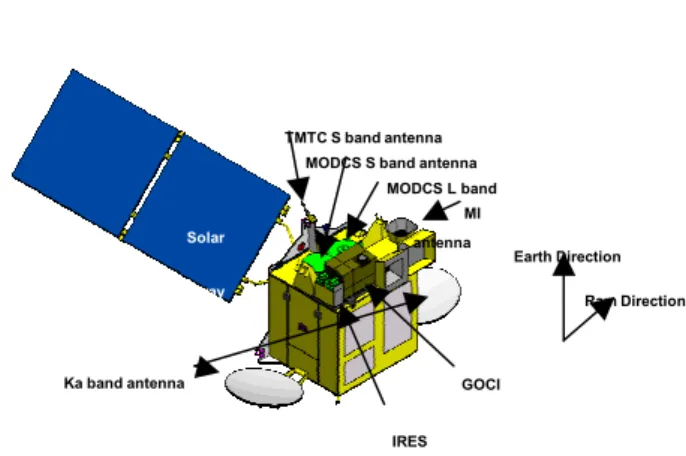
The COMS is a three axes stabilized satellite with single solar array wing. Due to the thermal effect on the meteorological payload, solar array wing cannot be installed on the other side. In previous three axes stabilized meteorological satellites, solar boom had been installed for momentum stability. But, the solar boom is eliminated in the COMS. Figure 2 shows the configuration of the COMS. In the figure, IRES is the infra-red Earth sensor. MODCS stands for Meteorological and Ocean Data Communication
Subsystem.
Figure 2. The configuration of the COMS.
L-band frequency (1670-1710 MHz) will be used for downlink of the meteorological and ocean monitoring raw data and processed meteorological data, and S-band (2025-2110 MHz) will be used for uplink of the processed meteorological data. Also, S-band will be used for satellite telemetry (2200-2290 MHz) and telecommand (2025-2110 MHz). The Ka-Band is used for communication services.
Operational life of the COMS is more than 7 years but the design life of the COMS is more than 10 years. The COMS can be stored for over 2 years in the container specially manufactured for the long-term storage.
The orbital location will be selected in the range between 116°E and 138°E. It will be finalized after the approval from ITU. The station keeping accuracy is ±0.5° in longitude and latitude of the normal orbital location throughout the operational lifetime.
4. METEOROLOGICAL IMAGER(MI)
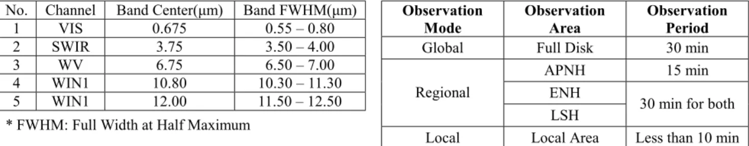
The specification of MI is similar to GOES or MTSAT- 1R. Table 3 shows the spectral channels and Table 4 shows radiometric performance.
Table 3. Spectral Channels of MI
MI
GOCI
IRES MODCS L band
antenna MODCS S band antenna
Ka band antenna
TMTC S band antenna
Solar
Array
Earth Direction Ram Direction
SOC(KARI)
Internet
End-users
) MSC(KMA)
KOSC(KORDI)
Exclusive line TM/TC
Raw data
LRIT/HRIT (backup) TM/TC
(backup) Raw data LRIT/
HRIT
LRIT/HRIT
Raw data
CTES(ETRI) COMS
V-001-8
) Ka-band
Communication End-users
3 No. Channel Band Center(µm) Band FWHM(µm)
1 VIS 0.675 0.55 – 0.80
2 SWIR 3.75 3.50 – 4.00
3 WV 6.75 6.50 – 7.00
4 WIN1 10.80 10.30 – 11.30
5 WIN1 12.00 11.50 – 12.50
* FWHM: Full Width at Half Maximum
Table 4. Radiometric Performance of MI
No. Channel SNR or NEdT Dynamic Range 1 VIS ≥10 at 5% albedo 0-115%
albedo 2 SWIR ≤5.7°K at 220°K
≤0.10°K at 300°K 4 - 350°K 3 WV ≤0.86°K at 220°K
≤0.12°K at 300°K 4 - 330°K 4 WIN1 ≤0.4°K at 220°K
≤0.12°K at 300°K 4 - 330°K 5 WIN1 ≤0.48°K at 220°K
≤0.20°K at 300°K 4 - 330°K
The Field of View of the MI is at least 19°x 17.6°covering the full Earth disc and the cold space around it. The resolution of the MI is 1km for the visible channel and 4km for the other channels.
The operational life of the MI is more than 7 years and the duty cycle of the MI normal operation mode except for standby mode is more than 95%. In the standby mode the MI is powered on and its command and telemetry connection is active while its image chain components in idle status.
The MI provides various observation modes. Table 5 shows the observation modes and its observation period.
And, Figure 6 shows the observation areas when the orbital location is 116°E. The local area of 1000km by 1000km for the local observation mode is selectable in the full disk.
Table 5. Observation Modes of MI
Observation
Mode Observation
Area Observation Period
Global Full Disk 30 min
APNH 15 min
Regional ENH
LSH 30 min for both Local Local Area Less than 10 min
*APNH: Asia Pacific in Northern Hemisphere
* ENH+LSH=LFD(Limited Full Disk)
Figure 6. MI Observation Areas
5. GOCI
The GOCI collects data in 8 spectral channels with a spatial resolution of about 500m around the Korean peninsula area of 2500km by 2500km centered at 36°N and 130°E. The spectral channels and their primary uses of the GOCI are summarized in Table 7.
The duty cycle requires 8 images during daytime and 2 images during night time. The maximum imaging time per image is 30 minutes. This includes integration, readout and download of the image data for 8 bands and dark signal acquisition. The size of the GOCI is about 975mm(W)x688mm(D)x650mm(H) and the mass of the GOCI is about 45.2kg.
Full Disk LSH(Limited Southern Hemisphere)
APNH
ENH(Extended Northern Hemisphere)
4 Table 7. Spectral Channels and Applications of GOCI
No. Band Center
Band
Width Primary Use
1 412 nm 20 nm Yellow substance and turbidity
2 443 nm 20 nm Chlorophyll absorption maximum
3 490 nm 20 nm Chlorophyll and other pigments
4 555 nm 20 nm Turbidity, suspended sediment 5 660 nm 20 nm Baseline of fluorescence
signal, chlorophyll, suspended sediment
6 680 nm 10 nm Atmospheric correction and fluorescence signal
7 745 nm 20 nm Atmospheric correction and baseline of fluorescence signal
8 865 nm 40 nm Aerosol optical thickness, vegetation, water vapor reference over the ocean
The GOCI will be operated in 3 modes – OFF mode, STSAND BY mode, IMAGING mode. There is no specific safe mode. The OFF mode will be used as safe mode. Direct transition from IMAGING mode to OFF mode is avoided, even in case of transition to safe mode in satellite level. The operational life time of the GOCI is more than 7 years.
6. SUBSYSTEM DESIGN
MODCS transmits the meteorological and ocean data to MSC, KOSC and SOC and relays the processed meteorological data to end users. Raw data transmission rate is 6Mbps, HRIT transmission rate is 3Mbps, and LRTI transmission rate is 256kbps.
The TC&R subsystem is designed with full redundancy except antenna and no permanent degradation results from recoverable undervoltage conditions. The ranging accuracy is better than 10m on station and 13.3m during transfer orbit maneuver. Bit Error rate is 1E-6 with 13m antenna for both uplink and downlink.
In EPS, the COMS solar array is made of one wing with two panels and the Gallium Arsenide triple junction solar cells are used. The battery type is Li-ion battery.
The AOCS is a three axis control system using the 5- wheel system and 7 thrusters. Attitude determination is achieved by using IRES(Infra-Red Earth Sensor), fine Sun sensor LIASS mounted on solar array, and FOG gyro. The coarse Sun sensor BASS is used for Sun acquisition and cruising in transfer maneuver.
PS is a heritage design of Eurostar bus. For transfer orbit operation, LAE(Liquid Apogee Engine) is used. SMS is a new design which is an enlargement of the MARS express model.
7. CONCLUSION
The system design of the COMS along with the subsystem design is introduced in this paper. The operation of the COMS in Asia-Pacific region will considerably improve the weather forecast accuracy this region. The various operation modes of the COMS meteorological payload provide flexibility in meteorological monitoring and the damage due to special weather can be considerably reduced with this flexibility. The ocean monitoring mission of the COMS is the first ocean monitoring in the geostationary orbit. This challenging mission will open a new research and application areas.
References [1] COMS Requirements Specification [2] COMS System Specification