1. INTRODUCTION
Intelligent Transportation System (ITS) stands in the spotlight of world wide. It can be grafted into the others, because it has the various themes of studying and self supported sources of power and system algorithm without the external system like autonomous driving vehicle. So it looks getting further and further.
Its purpose is a developing of an unmanned vehicle to be sure to avoid a collision with a sensing any objects and an obstacle avoidance algorithm. Fig. 1 shows the outline diagram for this study.
Fig.1 The outline diagram
This unmanned vehicle’s general system has made up with ATV(All Terrain Vehicle) with a gasoline 4 stroke engine and the obstacle avoidance algorithm using ultrasonic sensors.
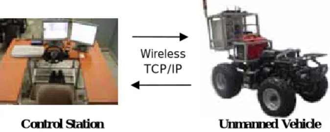
The telecommunication method has been confirmed experimentally between the unmanned vehicle and the control station using a wireless LAN(Local Area Network) is getting used more and more these days in moving environment.
It shows a structure and tele-operated control system for remote controlling in the second chapter, further presents a result of experiments in the third chapter.
2. SYSTEM CONFIGURATION
The most important part of the tele-operated control vehicle
system has three steps; First construction of the vehicle system and tele-operated control system, Second is a stability of the system structure and the driving; Third is the unification control algorithm between the above two systems
2.1 Structure of the unmanned vehicle system
The unmanned vehicle is divided into longitudinal, lateral control systems, and sensor system. The fig. 2 shows the configuration of the unmanned vehicle system.
Fig. 2 Configuration of the unmanned vehicle system 2.1.1 Longitudinal control
It has been controlled by servo motors which are connected with linking mechanism for a throttle, transmission and brake.
Fig. 3 Flow chart for longitudinal control
Design of Advanced Tele-operated Control System for Unmanned Vehicle
Jae Hong Park*, Young Jin Son**, and Jung Ha Kim***
*Graduate School of Automotive Engineering, Kookmin University(Tel : +82-2-910-5143; E-mail: [email protected]) **Graduate School of Automotive Engineering, Kookmin University
(Tel : +82-2-910-5143; E-mail: [email protected])
***School of Mechanical and Automotive Engineering, Kookmin University (Tel : +82-2-910-4715; E-mail: [email protected])
Abstract: It is materialized an unmanned vehicle system as a part of Intelligent Transportation System (ITS) which is a fundamental constituent for unmanned vehicle. Remote control system, monitoring system and remote operating system which are consisted of unmanned vehicle system. Network program by TCP/IP socket, and real-time control & operating controlled by servo-motors from a remote place, those are used to verify safety and stability of the unmanned vehicle system in this research. This unmanned vehicle is divided into two major sections which are an unmanned vehicle part and control station part. The server PC is installed on the unmanned vehicle and a client PC is installed at a remote place, which can control the unmanned vehicle. In this research work, main theme is that we experimented and tested to check the speed and utilization of the wireless LAN communication.
Keywords: Unmanned Vehicle System, Tele-operated System, Wireless LAN, Ultrasonic sensor
Control Station Wireless TCP/IP Unmanned Vehicle Load position Σ AlgorithmControl Power Amplifier DC Motor Gear Reduction and Load Position Sensor Error Controller Output Signal Motor Voltage Motor Output Torque Position Feedback
Warining light control
Fuel Idle switch Accelerator motor Gear motor position Brake motor position
Brake switch
DAQ Main power control
Stsrt motor control Fan motor control
Servo motor t ll
Accelerator motor
CCD camera Gear change motor
Brake motor
CCD camera motor RPM
Wireless video transmit Broadband router 2.4 GHz Wireless LAN 2.4 GHz SERVER PC Steering angle Vehicle speed Step motor controller Steering motor
Photo. 1 Servo motors and motor driver 2.1.2 Lateral Control
The lateral control is used by a step motor with a timing belt at a steering axle. It can be controlled with closed-loop mechanism by a position sensor at the bottom of the axle.
Fig. 4 Flow chart for lateral control system
Photo. 2 Steering motor and position sensor 2.1.3 Unmanned Vehicle Sensor System
The sensor system is classified into engine operated sensor, transmission operated sensor, and motor position measurement sensor parts. The measured data is used for driving and control factor for the unmanned vehicle.
Fig. 5 Unmanned vehicle sensor system 2.2 Tele-operated control system
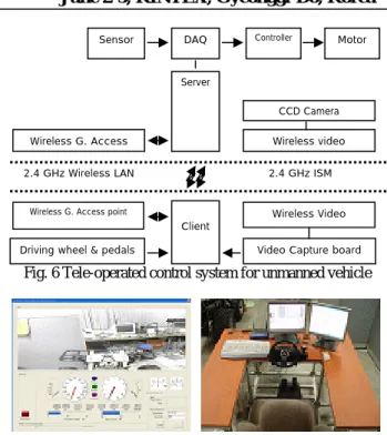
The data of speed and direction of unmanned vehicle is sent to the control station through the wireless LAN, so the operator can monitor vehicle system in a real time. Additionally, he can control the vehicle with the forward area using the camera which is mounted on the vehicle. The control inputs are sent to the unmanned vehicle with the driving simulator in the control station. Fig.6 is the concept of tele-operated system.
Fig. 6 Tele-operated control system for unmanned vehicle
Photo. 3 Tele-operated control program and control station 2.3 Telecommunication System
Ad-hoc mode would be made by settings of the access points at the unmanned vehicle and the control station. The non-directional antenna (8dB) would be set at the vehicle; the directional antenna (12dB) would be set at the control station for an increase of the driving distance.
Photo. 4 Directional antenna & Non-directional antenna 2.3.1 Stability of radio-frequency interference
This wireless LAN has been used for this study in frequency band of 2.4GHz for industry, science and medical science. So the normal condition could be interrupted and could be failed and could decline transmission speeds by radio-frequency interference. That is the reason why it needs to have a solution without radio-frequency interference.
In this research, the automatic client reconnection method could be used to have the stability that is checking the error codes in the packet while the TCP/IP communications are happened between the server and the client.
The client that can be finished the TCP/IP communications and convert the other TCP/IP communications, as soon as it is found the error codes. But client needs about 50 ~ 2000ms time to spare depending on the experiments in conformity with the telecommunication environment and the distances. The time delay would be a trouble for a driving vehicle to have stability.
To solve this problem, when the error codes appear to send the error signal on the motor controller, so the motor controller can controlled acceleration and the brake motor position (Fail mode). After it could be converted to the driving mode while
Σ
Command Position
Erro
Position Feedback
Controller Step Motor Driver Load Position
1. Accelerator Motor Position 2. Break Motor Position 3. Gear Motor Position 4. Steering Angle 5. Vehicle Speed 6. Engine RPM 7. Oil Temperature 8. Idle Switch 9. Break Switch 10. Fuel Vehicle Control Computer Sensor Controller Input Output
1. Main Power Control 2. Emergency Stop Control 3. Fan Motor Control 4. Warring System 5. Idle Speed Control 6. Vehicle Speed Control 7. Start Motor Control
8. Peripheral Equipment Control
Sensor
Server
Wireless G. Access Wireless video 2.4 GHz Wireless LAN 2.4 GHz ISM
Wireless G. Access point Client
Driving wheel & pedals Video Capture board Wireless Video DAQ Controller Motor
CCD Camera
Position Sensor
reconnecting, to have the stability and follow the orders. Furthermore, to consider the misoperation in the radio-frequency interference, the limit switch at the acceleration motor could turn off, makes the acceleration motor to the early stage and controls the brake.
Fig. 7 Automatic client reconnection method 2.4 Sensing and the avoidance of the obstacle
It could be possible to collide with the obstacles because of any mistake or the other conditions. Therefore, the avoidance should be considered seriously. To avoid, the vehicle could be avoided itself by the ultra sonic sensor, not to follow the tele-operated order anymore, when the obstacles appears. The fig.8 shows the configuration of the obstacle avoidance
Fig. 8 Block diagram of range measurement system
Photo. 5 Ultrasonic sensor on mounting of ATV This studying uses concept of gravitational field to the obstacle avoids. The minimum distance between the
obstacles and the vehicle is
D
min. The enough distance tostop the vehicle to reach the minimum distance is
D
s. Themaximum speed of the vehicle is
ν
max , the maximumacceleration is
α
max, the weight of the vehicle isM
R. Whenthe control input of the vehicle
ν
r,ω
ra are given, using the ultrasonic senor input datad
s of the vehicle, it could be hadfinal input value
ν
m,ω
m below.s R R R
M
x
M
D
M
max max 2 *2
1
ν
α
α
=
+
(2.4.1))
(
2
max *x
D
s−
=
α
ν
sD
=2
1
max 2 maxt
α
=max
2
2 maxα
ν
(2.4.2) mν
=ν
r , ifx
≤
0
=sgn(
v
r)
min(
v
r,
v
*)
ifx
>
0
)
(
2
max *x
D
s−
=
α
ν
,x
≤
D
s = 0 , ifx
>
D
s)
(
)
(
D
sD
mind
sR
sx
=
+
−
+
)
,
,
,
min(
0 1 N sd
d
d
d
=
K
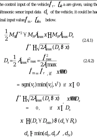
The Eq. 2.4.1 shows the speeds depending on
x
thatmeans to keep the minimum distance between the vehicle and the obstacles in the safety distance, the Eq. 2.4.2 shows the relations between the vehicles and the final control input to avoid the obstacles.
d
s is the distance from the vehicle to the obstacles,R
s is the distance from the vehicle’s center to the ultrasonic sensor.2.5 Unification System
Tele-operated control structure is made to the obstacle avoidance in Fig.9
Fig. 9 Unification System
The avoidance controller is not related with the Tele-operated control input.
A control order is sent of the unmanned vehicle to control it using a simulator from the remote control station.
It is made a closed loop in the now state, that is gotten feedback by the control station.
Range measurement computer in the vehicle finds out the information of the environment using the ultrasonic sensor, follows the orders without any collisions position. The fig. 9 indicates the configuration of obstacle avoidance system.
Control Station Obstacle Avoidance Driving Part Sensor Environment Position Velocity Position #1 Velocity #2 Obstacle data Unmanned Vehicle Driving data Range measurement computer Vehicle control computer Remote control computer TCP/IP Wireless LAN Unmanned Vehicle Connection Read/Write Close connection Fail Mode Normal Mode Error Code
True False
3. EXPERIMENTS AND RESULTS
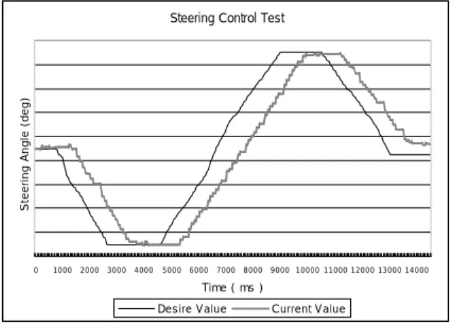
This research made the unmanned vehicle was remote controlled between the unmanned vehicle and the remote control system using the wireless LAN. It is the experiment to confirm the smooth corporation between the systems below. It checked out the vehicle’s feedback of the steering system with the driving simulator in the station for the longitudinal control experiment.
Steering Control Test
0 1000 2000 3000 4000 5000 6000 7000 8000 9000 10000 11000 12000 13000 14000 Time ( ms ) S te e ri ng A ng le ( d e g ) .
Desire Value Current Value
Fig.10 Result of steering control test
Fig. 10 is the result of the comparing with the steering angle measured by the position sensor and steering axis and the data of the driving controller at the remote control system. Following the results, driving simulator follows the steering input. The delay of 500~1000ms seems caused by the ratio of geared motor, the communication traffic, and friction force of ground.
Photo.6 Test course with Ultrasonic sensor Fig. 11 is the results of the obstacle distance measured by ultrasonic sensors while the tele-operated driving mode.
Obstacle distance of driving
0 0.5 1 1.5 2 2.5 3 3.5 4 4.5 5 43 .2 45 46 .8 48 .6 50 .4 52 .2 54 55 .8 57 .6 59 .4 61 .2 63 64 .8 66 .6 68 .4 70 .2 72 73 .8 75 .6 Time(sec) Di s ta n c e( m )
Right M iddle Left
Fig.11 obstacle distance measurement
Driving mode of obstacle avoidance algorism
0 0.5 1 1.5 2 2.5 3 3.5 4 4.5 5 43 .2 45 46 .8 48 .6 50 .4 52 .2 54 55 .8 57 .6 59 .4 61 .2 63 64 .8 66 .6 68 .4 70 .2 72 73 .8 75 .6 Time (sec) D is ta n ce (m ), D ri vi n g m o d e
Driving Control Mode Right Middle Left
Fig. 12 Driving mode of obstacle avoidance algorithm Fig. 12 is showing that the range measurement system equipped on unmanned vehicle how to decide to select driving modes; tele-operated, autonomous, emergency driving.
Driving pattern of advanced tele-operated control system
0 0.5 1 1.5 2 2.5 3 3.5 43.2 4546.848.650.452.2 5455.857.659.461.2 6364.866.668.470.2 7273.875.6 Time (sec) Dis ta n ce( m )
Desire value Current Value Driving Control M ode
Fig. 13 Driving pattern of advanced tele-operated control system
When the unmanned vehicle is tele-operated mode, it is happen to meet some obstacle which couldn’t be seen by the operator. At that time, the mode should be switched to the autonomous mode for avoidance independently.
The purposes of this experiment were to make up the unmanned vehicle system with ATV and to check out the stability and the safety using the ultrasonic sensor of the controlled vehicle. To add, it can be sure to possibility of the wireless LAN, being transmitted the information and being controlled the between the server and the client. But it needs to challenge to cover the time delay between the systems in the vehicle, and the inaccuracy of the ultrasonic sensor.
4. CONCLUSION
We would like to conclude our research work as following. 1) This is the case study of improving the stability and safety factors using ultrasonic sensors between the unmanned vehicle and the remote control systems.
2) It is reified that the method of wireless LAN communication system is more effective for the exchange and
transmission of data, and also it can be powerful for the future complicated unmanned vehicle system.
REFERENCES
[1] Tomas D, Gillespie, “Fundamentals of Vehicle Dynamics”, Society of Automotive Engineers, pp. 196-208, 1994.
[2] Sano, S., “Evaluation of Four-Wheel Steering Technology and its Future Prospects”, JSAE Review Vol. 9, No. 3, pp. 4-7, 1988.
[3] N. A. El-Esnawy and J. F. Wilson, “Lateral Dynamics and Stability of Two Full Vehicles in Tandem”, Journal
of Dynamic Systems, Measurement and Control, Vol. 120,
No. 1, 1998.
[4] S. J. Lee and W. J. Chung, “Mathematical Modeling for Cornering of Unmanned Vehicle”, Transactions of the
Korean Society of Machine Tool Engineers, Vol. 11, No.
1, pp. 70-76, 2002
[5] H.C.Moon, W.S.Lee, and J.H.Kim, “Advanced Lane Detecting Algorithm for Unmanned Vehicle”,
Proceeding of ICCAS 2003, pp. 1130-1133, 2003.
[6] Creighton Daniel and Walker Robert E., “A Two-Dimensional Vehicle-Media Interaction Model for Wheeled Vehicles”, Presented at the Wheels and Tracks
Symposium, 1998
[7] C. Samson and K. Ait-Abderrahim, “Feedback control of a nonholonomic wheeled cart in Cartesian space”,
International Conf. on Robotics and Automation, pp.
1136-1141, 1991.
[8] Mark Brudnak, Patrick Nunez and Alexander Reid, “Real-time, Distributed, Unmanned Ground Vehicle Dynamics and Mobility Simulation”, SAE International, 2002.
[9] T.Y.Chung, K.S. Yi, J.T. Kim and J.M. Lee, “Closed-Loop Evaluation of Vehicle Stability Control(VSC) System using a Combined Vehicle and Human Driving Model”, SAE International, 2004.