I. INTRODUCTION
In the wireless/mobile networks, the vertical handover across heterogeneous networks becomes one of the critical issues in the future wireless/mobile networks [1]. In the vertical handover, it is required to provide seamless services for a mobile terminal that moves across different types of access networks.
The Stream Control Transmission Protocol (SCTP) [2] was proposed to support the vertical handover in the transport layer with the help of the multi-homing feature and dynamic address reconfiguration extension [3], which is called mobile SCTP (mSCTP) [4]. mSCTP handover allows a Mobile Node (MN) to dynamically add a new IP address or delete an old IP address to or from the current SCTP association, as MN moves across different IP networks. During mSCTP handover, MN is required to switch the primary path from the old IP address to a new IP address.
In this paper, we consider the congestion control of mSCTP for vertical handover. The mSCTP is used for
vertical handover between heterogeneous wireless networks. However, there are still a lot of challenging issues to be solved in the mSCTP vertical handover. One of them is how to enhance the throughput of data transmission during vertical handover. In the mSCTP handover, each time the primary path is switched, the congestion control parameters of the new primary path will be initialized, and further the congestion window begins in the slow start phase [2]. This may cause the data transmission throughput to be degraded during handover. Such the throughput degradation could be more severe when MN moves across heterogeneous networks with quite different network bandwidths, as shown in the example of the vertical handover between 3G wireless and WLAN.
A couple of schemes have been made to enhance data transmission throughput during handover for the Transmission Control Protocol (TCP) over Mobile IP (MIP) [5]~[7]. The work of [5] proposed to immediately initialize the congestion control parameters during vertical handover. In the works of [6],[7], the authors proposed In this paper we discuss the congestion control of mobile Stream Control Transmission Protocol (mSCTP) for vertical handover across heterogeneous wireless/mobile networks. We propose a new congestion control scheme, which is based on estimation of available bandwidths in the new network that a mobile node moves into. By ns-2 simulation, the proposed scheme is compared with the existing ones in the throughput perspective. From the numerical results, we can see that the proposed congestion control scheme could give better performance than the existing schemes.
Keywords: SCTP, mSCTP, Congestion Control, Vertical Handover
논문번호: TR09-079, 논문접수일자:2009.08.10, 논문수정일자:2009.10.07, 논문게재확정일자:2009.10.15
Dong-Phil Kim: LG Electronics
Seok-Joo Koh: Kyungpook National University
mSCTP Congestion Control for Vertical Handover
Across Heterogeneous Wireless Networks
that the congestion control parameters should be adjusted based on the estimated bandwidth-delay product under the assumption that MN and Corresponding Node (CN) can know the available bandwidth beforehand. However, it is noted that TCP could not realize the change of IP address during movement, since it cannot exploit the transport-layer multi-homing capability.
In the meantime, several works have been made on the mSCTP handover. The work of [8] proposed an mSCTP handover, called SIGMA, and compared the handover latency of SIGMA and MIP on the various experimental testbeds. In [9], the mSCTP was compared with the MIP fast handover, in which the authors argue that mSCTP handover gives lower handover latency than MIP fast handover. The work in [10] proposed a new transport layer protocol based on SCTP, which is called Wireless SCTP Extension (WiSE), so as to improve the resource utilization by switching the primary path into an alternate path. On the other hand, a novel mSCTP handover scheme was proposed in [11], which is called Cellular SCTP (C-SCTP). In the C-SCTP scheme, a bicasting is used by CN to send duplicate data packets to both of the old and new IP addresses in the handover region. In particular, the C-SCTP sets the congestion window size of the new path to be the same with the congestion window size of the old path. This scheme will be helpful to avoid the under-utilization of the new link, but it did not consider the available network bandwidth of the new path. Thus, it may lead to the performance degradation due to the over-utilization of the new link.
In this paper, we propose a new congestion control scheme of mSCTP for vertical handover, in which the
congestion window size is configured based on the available bandwidth estimated in the concerned network, so as to provide efficient data transmission during handover. For performance analysis, we perform ns-2 simulations and compare the proposed scheme with the existing schemes for a variety of test environments with some background traffics.
The rest of this paper is organized as follows. Section II describes the existing congestion control schemes. Section III presents the proposed congestion control scheme for mSCTP vertical handover. Section IV discusses the simulation results. Finally, we conclude this paper in Section V.
II
. Existing Schemes for mSCTP
Handover
1. Overview of mSCTP Handover
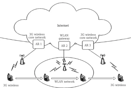
In mSCTP handover, each endpoint is able to add or delete an IP address to or from the existing association, and also to change its primary IP address. Figure 1 illustrates the protocol operation of mSCTP handover across different IP networks [4].
In the figure, we assume that MN initiates an SCTP association with CN, and moves from the Access Router 1 (AR1) region to AR2 region. For the SCTP association, MN initially uses
'
IP address 1'
in the AR1 region. Then, the overall mSCTP handover procedures could be performed as follows.When MN moves into AR2 region, it obtains a new Access Router 1 Internet Correspondent Node Access Router 2 Mobile Node IP address 1 Mobile Node IP address 2 Figure 1. mSCTP handover Overlap Region
ⓑ, the congestion window size of the new path is identical to that of the old path at the time of primary path switching.
It is noted that these two extreme cases did not consider the current network conditions such as the available network bandwidth. Accordingly, the network bandwidth of the new path tends to be under-utilized in the conservative scheme, or over-utilized in the aggressive scheme. Such the problem may become more severe, when MN moves across heterogeneous wireless access networks with quite different link characteristics such as 3G wireless (with the link capacity of 384 Kbps) and WLAN (with the link capacity of 11 Mbps). When MN moves from 3G wireless to WLAN, the conservative scheme may result in the low utilization of the network bandwidth. On the reverse, when MN moves from WLAN to 3G, the aggressive scheme may induce over-utilization of network bandwidth for the new path, together with much packet loss or congestion.
In this paper, the link capacity represents the maximum link bandwidth that can be allowed to an individual user in the network, which will be different as per the underlying link-layer technology. We assume that the link capacity of 3G wireless is 384 Kbps, whereas the link capacity of WLAN is 11 Mbps. In particular, we will focus on a single mobile user in the wireless network. Furthermore, in the ns-2 experimentations, the congested network will be simulated by adding some background traffics to the wireless link that is connected to the concerned mobile user, rather than over entire network.
In this paper, we propose an adaptive congestion control scheme of mSCTP for vertical handover, in which the congestion window size of the new path is adaptively configured, based on the estimation of the available bandwidth in the new network so as to provide the efficient data transmission during handover.
III. PROPOSED CONGESTION
CONTROL SCHEME
1. Overall Procedures
In the proposed congestion control scheme, the initial congestion window size of the new primary path is configured adaptively based on the estimation of the available network bandwidth. To describe the proposed scheme, we will focus on the data transmission from CN to MN, and consider the movements of MN from 3G to WLAN and then from WLAN to 3G, as depicted in Figure 2.
address
'
IP address 2'
by using IP address configurationscheme such as Dynamic Host Configuration Protocol (DHCP). After that, the newly obtained IP address 2 will be informed to CN in the transport layer. This is done by sending an SCTP Address Configuration (ASCONF) chunk to CN. MN receives the responding
ASCONF-ACK chunk from CN. This is called the
'
Add-IP'
operation, during which the old IP address 1 is still used as the primary address. As MN further continues to move toward AR2 region, it will set the new IP address to be its primary address. For this purpose, MN sends an ASCONF chunk over IP address 1 and receives the responding ASCONF-ACK chunk from CN over IP address 2. Once the primary address is changed, CN sends the subsequent data packets over the new primary IP
address of MN (IP address 2). This is called the
'
PrimaryPath Switching
'
operation. As MN continues to movetoward AR2, it will delete the old IP address from the
association. This is called the
'
Delete-IP'
operation. Theseprocedural steps will be repeated each time MN moves to a new network.
2. Existing mSCTP Congestion Control
Schemes
Data transmission between two endpoints is performed as per the SCTP congestion control. When MN is multi-homed with two or more IP addresses, CN will separately manage the congestion control parameters per IP address of MN. For example in Figure 1, when MN enters the AR2 region in the multi-homing state, CN has to configure the congestion control parameters for the new IP address of MN. The existing configuration schemes of the congestion window can be classified as follows:
ⓐ Conservative scheme: initialize the congestion window size and perform the congestion control in the slow start mode, as per IETF RFC 4960 [2];
ⓑ Aggressive scheme: inherit the congestion window size of the old path at the time of the primary path switching (handover), as shown in the C-SCTP [11].
In the conservative scheme of case ⓐ, when MN switches the primary path, CN begins transmission of data packets with an initial congestion window in the slow start phase. We assume that the initial congestion window starts with 2・MTU, even though the IETF RFC 4960 [2] says that the initial congestion window is set to the minimum value between 4・MTU and the maximum of
the estimated bandwidth is too much over-estimated or under-estimated, the subsequent data transmission may lead to the performance degradation. Thus, the network bandwidth needs to be estimated accurately.
Until now, a lot of bandwidth estimation techniques have been proposed to determine the available network bandwidth on the bottleneck link. The self-loading techniques, including the Train Of Packet Pairs (TOPP)
[12], pathLoad [13] and pathChirp [14], are used to probe
the end-to-end network path using the multiple probing rates. When the probing rate exceeds the available bandwidth, the probing packets will be queued at the routers, which results in the increased delay. By analyzing the packet delay, the available bandwidth is calculated from the probing rate when the queuing delay begins to increase.
Packet dispersion techniques, such as the packet pair or packet train probing [15], [16], are used to measure the end-to-end capacity of a network path. In the packet dispersion techniques, two or more packets are transmitted into the network in the back-to-back fashion. After the packets traverse the narrow link, the time dispersion between the two packets is linearly related to the narrow link capacity. This packet dispersion scheme for capacity estimation may be vulnerable to crossing traffics that interfere with the probing packets and cause some estimation errors under variable channel conditions of wireless networks.
In the meantime, the Wireless Bandwidth Estimation Tool (WBEST) [17], [18] was designed to estimate the In the AR1 region, MN communicates with CN via 3G
link. When MN moves into WLAN hotspot, it will automatically configure a new IP address using DHCP. Then, MN adds the new IP address to the SCTP association by performing the mSCTP
'
Add-IP'
operation. After that, MN performs the primary path switching operation in the WLAN network. When MN leaves WLAN hotspot toward 3G wireless, it deletes the old IP address from the association by performing the mSCTP'
Delete-IP'
operation.The congestion control scheme of mSCTP proposed in this paper can be summarized as follows:
① MN performs the Add-IP operation with the help of the underlying link-layer trigger (e.g., link-up);
② CN estimates the available network bandwidth of the new path, until the primary path is switched;
③ CN is informed from MN about the primary path switching event;
④ CN calculates the initial congestion window of the new path, based on the estimated bandwidth; and
⑤ CN transmits the data transmission to the new primary path, as per the congestion control scheme.
2. Estimation of Available Network
Bandwidth
The proposed congestion control scheme configures the congestion window size of the new primary path, adaptively based on the estimated network bandwidth. If
3G wireless core network AR 1 AR 2 AR 3 WLAN network 3G wireless
Figure 2. Vertical handover between 3G and WLAN
3G wireless WLAN
gateway IInntteerrnneett
3G wireless core network
1.2. Calculate the effective capacity based on the n pairs of HEARTBEAT-ACK chunks from MN
•Step 2: Measure the available network bandwidth B(k),
as done in the 2ndstep of the WBEST scheme.
2.1. Send m pairs of HEARTBEAT chunk train at the rate C to MN
2.2. Calculate the available bandwidth, based on the responding HEARTBEAT-ACK chunks
•Step 3: If the primary path was switched into the new path, then stop. Otherwise, go to Step 4.
•Step 4: B(k)=
α
B(k)+(1-α
) B(k-1), where 0<α
<1.Set k=k+1. Go to Step 1.
Note that the initial B(0) is given by the real capacity of the new link (e.g., 11 Mbps for WLAN).
CN begins the above algorithm when the Add-IP operation is performed, and stops when the Primary-Switching is completed, as described in Step 3. The algorithm is based on the existing WBEST scheme. However, instead of UDP-based probe packets, we use the SCTP HEARTBEAT chunk with 700 bytes and SCTP HEARTBEAT-ACK chunk with 40 bytes. In Step 4, the estimated network bandwidths are averaged with the weighting coefficient (
α
). In the proposed scheme,α
is set to 0.7, which is an empirically obtained value that has given the best performance in our prior simulations.In the proposed bandwidth estimation technique, the packet pairs of HEARTBEAT and HEARTBEAK-ACK chunks are exchanged over the new path, not the primary (old) path for data transmission, so as to estimate the available bandwidth of the new path. It is noted that such control chunks can be transmitted over the newly added path, since the corresponding IP address already became one of the available path for the SCTP association through the Add-IP operation [2], [3].
3. Adaptive Configuration of Congestion
Window
Based on the effective capacity and available bandwidth estimated from the modified WBEST algorithm, CN will calculate a new congestion window size of the new path. The specific calculation of the new congestion window depends on the type of movement of MN.
First, when MN moves from 3G to WLAN, the Bandwidth-Delay Product (BDP) will be drastically increased. In such a scenario, the aggressive scheme (described in Section II) may be beneficial to fully utilize the link capacity of WLAN. In this case, it is preferred to set the new congestion window (of the new path) as the effective capacity and the available network bandwidth in
the wireless networks. The WBEST employs the packet dispersion techniques to provide capacity and available bandwidth information for the underlying wireless networks. In the works in [17], [18], the two metrics for packets dispersion are used: effective capacity and achievable throughput. By combining these two metrics, the WBEST uses a two-step algorithm, which can be used to firstly estimate the effective capacity and then statistically detect the available fraction of the effective capacity. In the first step, so as to estimate the effective capacity (C), CN sends the n pairs of packets to MN, and then receives the responding packet pairs from MN. For each of the received n packet pairs, CN calculates the packet dispersion time (i.e., the packet inter-arrival time between a pair of packets) Ti, for i=1, , n. Then, the effective capacity Ci for the i-th packet pair is calculated as Ci=L/Tiwhere L represents the length of the transmitted packets. To minimize the impact of crossing and contending traffic, the median of the estimated values is taken as follows: C=median(Ci) for i=1, , n. In the second step, a packet train (pairs) of m packets will be transmitted at the rate of C in the similar way as in the first step, so as to estimate the available network bandwidth (B). Then, B is calculated with the average packet dispersion rate (R=L/mean(Ti, i=1, , m)) and the effective capacity C, as follows: B=C [2-(C/R)]. When some packet losses are detected during the estimation, the available network bandwidth will be determined by B=B
(1-p) for the measured packet loss rate p.
In summary, for estimation of the available bandwidth, the WBEST scheme in [17], [18] seems to be the most suitable in the wireless networks in terms of accuracy, intrusiveness and short convergence time than any other schemes. Accordingly, in this paper, we employ the WBEST scheme to estimate the available bandwidth of the new primary path.
To apply the WBEST algorithm to the proposed congestion control scheme, some minor modifications are made as follows:
2.1. Modified WBEST Algorithm
When a new address of MN is informed in the Add-IP operation, CN performs the following iterations:
•Set k=1 (k is the iteration number).
•Step 1: Measure the effective capacity C, as done in the first step of the WBEST scheme.
old congestion window (of the old path), if possible. Accordingly, we use the following equation to configure the initial congestion window of the new path:
Bnew
CWNDnew=CWNDold×--- (1)
Cnew
In Equation (1), CWNDnew is the initial congestion
window of a new primary path and CWNDoldis the current
congestion window of the old path. Bnewand Cnew are
calculated from the modified WBEST algorithm. In the
equation, CWNDnewwill be set as large as CWNDoldif the
new path has the enough network bandwidth (i.e., Bnewis
nearly identical to Cnew). In the opposite case, CWNDnew
will be set to a small size.
On the other hand, in the movement from WLAN to 3G, the BDP will be reduced after handover. In this case, the aggressive scheme of Equation (1) may lead to the over-utilization of the link. Therefore, we calculate
CWNDnewbased on the BDP value of a new path, instead
of the CWNDold, as expressed in the following equation:
Bnew
CWNDnew=BDPnew×--- (2)
Cnew
In Equation (2), BDPnew is the BDP value of a new
primary path, which is calculated with the effective capacity and the minimum Round Trip Time (RTT) value,
i.e., BDP=Cnew×RTTmin. To measure the RTT between
CN and MN, we exchange the SCTP HEARTBEAT and HEARTBEAT-ACK chunks with the timestamp fields in
Step 2 of the modified WBEST algorithm. RTTmin is
given by the minimum value among the measured RTTs. Note that Equation (1) and (2) can be summarized as follows:
Bnew
CWNDnew=MIN(CWNDold, BDPnew)×--- (3)
Cnew
As depicted in Equation (3), the initial congestion window of the new primary path will be calculated as the minimum between the congestion window of the old path and the BDP value of the new path.
IV. NUMERICAL RESULTS
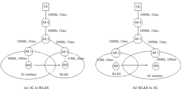
In this section, we present the performance analysis of the proposed mSCTP congestion control scheme using ns-2 network simulator [19]. For simulation, we consider the two types of movement of MN: from 3G to WLAN and from WLAN to 3G, as shown in Figure 3. Moreover, the data packets flow from CN to MN. We also note that the proposed scheme can be applied to data transmissions
CN
AR 4
AR 3
MN MN
3G wireless
(a) 3G to WLAN (b) WLAN to 3G
Figure 3. Test movement scenarios WLAN AR 1 AR 2 100Mb, 15ms 100Mb, 15ms 100Mb, 15ms 11Mb, 20ms 100Mb, 15ms 384Kb, 100ms CN AR 4 AR 3 MN MN 3G wireless WLAN AR 2 AR 1 100Mb, 15ms 100Mb, 15ms 100Mb, 15ms 384Kb, 100ms 100Mb, 15ms 11Mb, 20ms
from MN to CN, if CN is also in the heterogeneous networks, in which the bandwidth estimation will be done at the MN side.
In Figure 3(a), MN initially receives the data packets of the file transfer application in the 3G network. Then, MN moves into the WLAN and switches the primary path to the new IP address. In Figure 3(b), MN begins the data communications in the WLAN and then moves into the 3G network.
The parameters used for simulation are set as follows. The fixed/wired links between CN and the access routers are all set to be 100Mbps of bandwidth and 15ms of transmission delay. 3G wireless link of MN is set to 384Kbps and 100ms, whereas WLAN link of MN is set to 11Mbps and 20ms. Maximum Transfer Unit (MTU) is set to 1500 bytes. On the other hand, the primary path is switched from 3G wireless to WLAN links at the time of 30s. The simulation is performed over the 60 seconds. All the simulation results are averaged for the 10 test instances.
To perform the bandwidth estimation, we set the number of packet pairs (n) and the length of packet trains (m) to be 6 and 30 for the movement from 3G to WLAN, as recommended in [17], [18]. On the other hand, in the case of the movement from WLAN to 3G, we set n and m as 4 and 12, respectively, which are based on the prior empirical simulations.
In the experiments, so as to simulate the network congestion status, we will generate some background
traffics over the concerned wireless link that the mobile node is attached to, rather than over the entire wireless network.
1. Accuracy of Bandwidth Estimation
Before going further to the performance analysis of the proposed scheme, we first evaluate the accuracy of the modified WBEST algorithm in the viewpoint of the bandwidth estimation. For this purpose, we first run an SCTP association in the test networks of Figure 3. Each of three UDP-based CBR sources generates background traffics irregularly at the rate of 2Mbps for WLAN and 100Kbps for 3G.
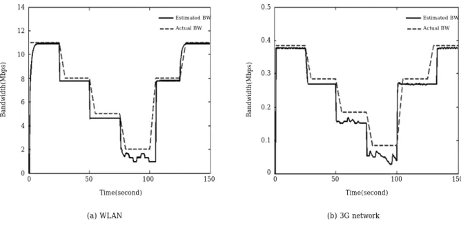
Figure 4 shows the actual bandwidth and the estimated bandwidth given by the modified WBEST scheme, when MN moves from 3G to WLAN (Figure 4(a)) and from WLAN to 3G (Figure 4(b)). At the beginning of the simulation (i.e., at the time of 0s), all the UDP connections are off. At the time of 25s, the first UDP connection is activated; the second UDP connection is at the time of 50s; the third connection is at the time of 75s; the first and second UDP connections are off at the time of 100s; finally, the third connection is off at the time of 125s.
In Figure 4(a) and 4(b), it is shown that the estimated bandwidth is almost identical to the actual bandwidth when there is no background traffic (i.e., until the time of 25s). As the background traffic increases, the estimated bandwidth seems to be slightly lower than the actual
14 12 10 8 6 4 2 0 Bandwidth(Mbps) Estimated BW Actual BW 0 50 100 150 Time(second) 0.5 0.4 0.3 0.2 0.1 0 Bandwidth(Mbps) Estimated BW Actual BW 0 50 100 150 Time(second)
(a) WLAN (b) 3G network
bandwidth. This is because the probing packets used for bandwidth estimation are lost due to the congestion, and the modified WBEST tends to reduce the estimated bandwidth according to the loss rate. Such the pattern continues as the amount of background traffic becomes larger, as shown at the time of 75s and 100s in Figure 4(a) and 4(b). It is noted that this slight under-estimation can be helpful to prevent the excessive data transmission when the new path is in congestion. From these empirical results, we can see that the modified WBEST scheme can give a reasonable estimation of the available network bandwidth even in the congested networks.
Now, we will compare the performance of the proposed congestion control scheme with the two existing schemes: the normal mSCTP (conservative) scheme [4] and the Cellular SCTP (aggressive) scheme [11]. In particular, we consider Cellular SCTP (C-SCTP) without bicasting mechanism, since the main purpose of this paper is to analyze the performance of the congestion control schemes during handover. In the experiments, all the candidate schemes use a common value of the slow start threshold, as described in Section III.
2. Movement from 3G to WLAN
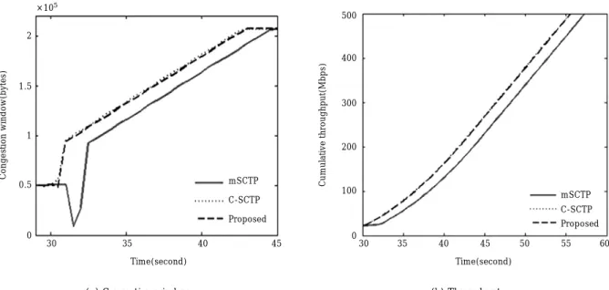
First, we compare the performance of the three candidate schemes for congestion control, when there is no background traffic, as shown in Figure 5.
In Figure 5(a), CN initially sends the data packets in the 3G network. When MN enters the WLAN network, CN switches the primary path into the WLAN link at the time of 30s. At this time, we can see that the proposed scheme increases the congestion window faster than the normal mSCTP scheme does. Thus, the proposed scheme gives better throughput than the normal mSCTP scheme, as shown in Figure 5(b). Such a performance gain comes because the proposed scheme adaptively calculates a new congestion window based on the bandwidth estimation for the new primary path (i.e., WLAN). On the other hand, it is observed in Figure 5(b) that the throughput of the proposed scheme is almost identical to that of C-SCTP. This is because the congestion window size obtained in the proposed scheme is nearly equivalent to the congestion window size of the old path (i.e., 3G), as done in the C-SCTP scheme.
Figure 6 shows the performance of the proposed and existing schemes when the background traffic is generated by 40% of the WLAN link capacity.
In Figure 6(a), it is observed that the proposed scheme increases the congestion window faster than the normal mSCTP scheme, even when there is the background traffic with 40% of the WLAN link capacity. In Figure 6(b), the proposed scheme outperforms the normal mSCTP scheme, as similarly in Figure 5(b). On the other hand, we can see in Figure 6(a) and 6(b) that a new congestion window of the proposed scheme is a little less than that of C-SCTP
2 1.5 1 0.5 0 Congestion window(bytes) mSCTP C-SCTP Proposed mSCTP C-SCTP Proposed 30 35 40 45 Time(second) ×105 500 400 300 200 100 0 Cumulative throughput(Mbps) 30 35 40 45 50 55 60 Time(second)
(a) Congestion window (b) Throughput
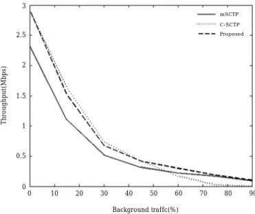
proposed schemes give better performance than the mSCTP scheme, until the background traffic is loaded by 45% of the WLAN capacity. When the offered background traffic is greater than 45% of the WLAN capacity, the proposed scheme outperforms the C-SCTP scheme as well as the mSCTP scheme. On the other hand, the proposed scheme tends to give a similar throughput as the mSCTP scheme in the highly congested network. scheme. This is because the proposed scheme tends to
slightly underestimate the available network bandwidth, when there is the background traffic.
Figure 7 compares the throughputs of mSCTP handover for the candidate schemes for different network loads (background traffic), in which the total throughputs are plotted over the entire simulation period.
In the figure, we can see that the C-SCTP and the
3 2.5 2 1.5 1 0.5 0 Throughput(Mbps) mSCTP C-SCTP Proposed 0 10 20 30 40 50 60 70 80 90 Background traffc(%)
Figure 7. Comparison of throughput for various background traffics 2 1.8 1.6 1.4 1.2 1 0.8 0.6 0.4 0.2 0 Congestion window(bytes) mSCTP C-SCTP Proposed mSCTP C-SCTP Proposed 25 30 35 40 45 50 55 60 Time(second) ×105 350 300 250 200 150 100 50 0 Cumulative throughput(Mbps) 30 35 40 45 50 55 60 Time(second)
(a) Congestion window (b) Throughput
3. Movement from WLAN to 3G
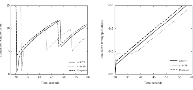
Figure 8 shows the performance comparison of the candidate schemes for movement from WLAN to 3G, in which no background traffic is given.
In Figure 8(a), MN begins data communications in the WLAN and then switches the primary path into the 3G
network at the time of 30s. At this time, we can see that the congestion windows of the all the schemes are decreased because the respective BDP values are reduced after handover (WLAN to 3G). In particular, the congestion window of the C-SCTP scheme begins to decrease around the time of 32s, which is slightly later compared to the other schemes. This is because in the
C-×104 15 10 5 0 Congestion window(bytes) mSCTP C-SCTP Proposed mSCTP C-SCTP Proposed 30 35 40 45 50 55 60 Time(second) 650 645 640 635 Cumulative throughput(Mbps) 30 35 40 45 50 55 60 Time(second)
(a) Congestion window (b) Throughput
Figure 8. Performance of mSCTP handover without background traffic
14000 12000 10000 8000 6000 4000 2000 0 Congestion window(bytes) mSCTP C-SCTP Proposed mSCTP C-SCTP Proposed 30 35 40 45 50 55 60 Time(second) 643 642 641 640 639 638 637 636 635 Cumulative throughput(Mbps) 30 35 40 45 50 55 60 Time(second)
(a) Congestion window (b) Throughput
V. CONCLUSIONS
In this paper, we have proposed an adaptive congestion control scheme of mSCTP for vertical handover across heterogeneous wireless networks. In the existing schemes, the initial congestion window size of the new primary path is configured in the conservative or aggressive way, irrespective of the network conditions such as available network bandwidth. These schemes tend to induce the under- or over-utilization of the bandwidth in the new network.
To cope with such a problem, we proposed an adaptive mSCTP congestion control scheme, in which the available network bandwidth is estimated and then the congestion window of the new primary path is calculated based on the estimated network bandwidth. By the ns-2 simulations, we compared the proposed scheme and the two existing schemes for mSCTP vertical handover between 3G wireless and WLAN.
From the simulation results, we can see that the proposed scheme gives better throughput than the two existing schemes by adaptively configuring the congestion window of the new primary path according to network conditions. However, it seems that all of the candidate schemes tend to give similar throughputs in the highly congested network.
To apply the proposed scheme in real networks, some further works are still needed, which may include the consideration of different mobility patterns such as ping-SCTP scheme the congestion window is decreased just
after CN experiences some packet losses with the retransmission timeouts. Therefore, the corresponding throughputs will be degraded, as the simulation time goes on, as shown in Figure 8(b). On the other hand, the proposed scheme outperforms the existing two schemes in the throughput perspective.
Figure 9 shows the performances when the background traffic is generated by 40% of the 3G link capacity of the mobile user.
In Figure 9(a), the congestion window of C-SCTP continues to fall down until the time of 35s, since it induces the frequent packet losses and the subsequent retransmission timeouts due to the background traffic. The proposed scheme tends to configure the congestion window size larger than the mSCTP scheme, and thus the proposed scheme provides better throughout than the mSCTP scheme, as shown in Figure 9(b).
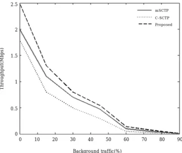
Figure 10 shows the throughput of the candidate schemes for a variety of background traffic.
In Figure 10, we can see that the proposed scheme outperforms the existing two schemes in the throughput perspective, until the background traffic is loaded by 70% of the 3G link of the user. When the offered background traffic is greater than 70% of the link, all of the candidate schemes seem to provide the similar throughputs. This is because all of the candidate schemes experiences the frequent packet losses and thus retransmission timeouts in the highly congested network links.
2.5 2 1.5 1 0.5 0 Throughput(Mbps) mSCTP C-SCTP Proposed 0 10 20 30 40 50 60 70 80 90 Background traffic(%)
pong movement, the performance analysis with a variety of performance metrics, such as the fairness and the control overhead associated with bandwidth estimation, and the study of mSCTP with various bandwidth estimation techniques under different network environments.
Acknowledgement
This research was supported by the MKE (The Ministry of Knowledge Economy), Korea, under the ITRC (Information Technology Research Center) support program supervised by the NIPA (National IT Industry Promotion Agency): (NIPA-2009-C1090-0902-0009).
[References]
[1]
A. K. Salkintzis, ''Interworking Techniques and
Architectures for WLAN/3G Integration toward 4G
Mobile Data Networks,'' IEEE Wireless
Communications, Vol. 11, No. 3, Jun. 2004, pp. 50-61.
[2]
R. Stewart, et al., Stream Control Transmission
Protocol, IETF RFC 4960, Sep. 2007.
[3]
R. Stewart, et al., Stream Control Transmission Protocol
(SCTP) Dynamic Address Reconfiguration, IETF RFC
5061, Sep. 2007.
[4]
S. Koh, et al., ''mSCTP for Soft Handover in Transport
Layer,'' IEEE Communications Letters, Vol. 8, No. 3,
Mar. 2004, pp. 189-191.
[5]
K. Tsukamoto, et al., ''New TCP Congestion Control
Schemes for Multimodal Mobile Hosts,'' IEICE
Transaction of Communications., Vol. E89-B, No. 6,
Jun. 2006, pp. 1825-1836.
[6]
S. Kim, et al., ''TCP for Seamless Vertical handoff
in Hybrid Mobile Data Networks,'' Proceeding of
IEEE GLOBECOM, Vol. 2, Dec. 2003, pp. 661-665.
[7]
E. Ko, et al., ''Dealing with Sudden Bandwidth
Changes in TCP,'' Proceeding of IEEE ICC, May 2008,
pp. 3007-3011.
[8]
S. Sivaqurunathan, et al., ''Experimental Comparison
of Handoff Performance of SIGMA and Mobile IP,''
Proceeding of HPSR, May 2005, pp. 366-370.
[9]
C. K. Ken, et al., ''Handoff Performance Comparison
of Mobile IP, Fast Handoff and mSCTP in Mobile
Wireless Networks,'' Proceeding of I-SPAN 2008, May
2008, pp. 45-52.
[10] R. Fracchia, et al., ''WiSE: Best-path Selection in
Wireless Multihoming Environments,'' IEEE
Transactions on Mobile Computing, Vol. 6, No. 10,
Oct. 2007, pp. 1130-1142.
[11] I. Aydin, et al., ''Cellular SCTP: A Transport-Layer
Approach to Internet Mobility,'' Proceeding of ICCCN,
Oct. 2003, pp. 285-290.
[12] B. Melander, et al., ''Regression-based Available
Bandwidth Measurement,'' Proceeding of SPECTs,
Jul. 2002.
[13] M. Jain, et al., ''End-to-end Available Bandwidth:
Measurement Methodology, Dynamics, and Relation
with TCP Throughput,'' IEEE/ACM Transactions
on Networking, Vol. 11 , Issue 4, Aug. 2003,
pp. 537-549.
[14] V. Ribeiro, et al., ''pathchirp: Efficient Available
Bandwidth Probing Techniques,'' IEEE Journal on
Selected Area in Communications, Vol. 21, No. 6,
Aug. 2003.
[15] S. Keshav, ''A Control-Theoretic Approach to
Flow Control,'' Proceeding of the ACM SIGCOMM,
Sep. 1991, pp. 3-15.
[16] K. Lakshminarayanan, et al., ''Bandwidth Estimation
in Broadband Access Networks,'' Proceeding of
ACM SIGCOMM Conference on Internet
Measurement, Oct.2004, pp. 314-321.
[17] M. Li, et al., ''Packet Dispersion in IEEE 802.11
Wireless Networks,'' Proceeding of IEEE LCN,
Nov.2006, pp. 721-729.
[18] M. Li, et al., ''WBEST: a Bandwidth Estimation Tool
for Multimedia Streaming Application over
IEEE 802.11 Wireless Networks,'' Proceeding of
IEEE LCN, Oct. 2008.
Dong-Phil Kim
He received the B.S. degree in the Department of Computer Science in Inje University, Korea in 2003. He received the M.S. degree and the Ph. D degree in the Department of Information Security in the Kyungpook National University, in 2005 and 2009, respectively. He is now with the LG Electronics Co. His research interests include the wireless networks and systems beyond 3G, Internet mobility and mSCTP.
E-mail: [email protected]
Seok-Joo Koh
He received B.S. and M.S. degrees in Management Science from KAIST in 1992 and 1994, respectively. He also received Ph.D. degree in Industrial Engineering from KAIST 1998. From August 1998 to February 2004, he worked for Protocol Engineering Center in ETRI. He is now an Associate Professor at Electrical Engineering and Computer Science in the Kyungpook National University since March 2004. His current research interests include the architecture and mobility control for Future Internet, Mobile Multicasting for IPTV, and mSCTP handover. He has so far participated in the International standardization as an editor in ITU-T SG13 and ISO/IEC JTC1/SC6. E-mail: [email protected]