A Study on the Characteristics of Volumetric Efficiency of an Axial
Piston Pump considering Piston Tilting
In-Kyu Park1 and Yoon-Chul Rhim2,†
1GT&E Co.,LTD, Seoul Korea
2School of Mechanical Engineering, Yonsei University, Seoul, Korea
(Received 3 November 2009; Revised 10 December 2009)
Abstract: This paper presents the characteristics of volumetric efficiency of an axial type piston pump considering the piston tilting. A numerical analysis is carried out in order to obtain the pressure distribution considering the fluid inertia at the notch of the valve plate. The cylinder pressure variation and the discharge flow rate are measured experimentally according to the operating conditions such as supply pressure, rotational speed, and viscosity of the working fluid by using the cam type test apparatus. Leakage is also measured considering piston tilting. The characteristics of the volumetric efficiency are analyzed with respect to various operating conditions and leakage is also analyzed according to the piston tilting angle. Results are applicable to improve the design of an axial type piston pump.
Keywords: Axial type piston pump, piston tilting, pressure variation, flow rate, leakage, cylinder, supply pressure, rotational speed, viscosity of working fluid
1. Introduction
The conventional hydraulic power system, which transfers fluid energy to each actuator via flow, direction, and pressure control valves and pipe lines from the hydraulic pumps, requires large capacity pumps to satisfy instant flow rate and pressure of the circuit. Therefore, the conventional hydraulic power system is heavy due to the huge pump, many circuit components, and complicate pipe lines. The system efficiency is low due to the leakage and viscous friction of the working fluid. Recently, an Electro-Hydraulic Actuator (EHA) system is introduced into the market to reduce unnecessary pipe lines as well as high price components and to increase the system efficiency. An EHA system is composed of small size motor, pump, and actuator with reservoir so that the tailored hydraulic power is supplied where large force or high torque is required. Each EHA system is controlled by an electrical signal so that the control system is much simpler, cheaper, and lighter than the conventional hydraulic power system. In order to realize high efficiency of the EHA system, a small-size high speed and high pressure pump is required.
A reciprocal type piston pump is known to be the best for this purpose. A swash plate type axial piston pump is simple in structure and in mechanism but the friction control between the
swash plate and piston foot is sophisticated and not easy to make its form factor small compared to the bent axis type axial piston pump, which has relatively more components.
It is very important for the bent axis type axial piston pump to minimize the friction loss and the leakage to keep the optimal lubrication condition. Helgested [1] suggested the equation for solving the pressure inside of the cylinder numerically, which is the main reason for the noise and vibration of the pump, and reported the results about the noise and the pressure variation inside of the cylinder according to the shape of the notches on the valve plate. Zeiger [2,3] analyzed the pressure variation inside of the cylinder according to the rotational speeds and the inclined angles of the swash plate. Edge [4,5] analyzed the pressure rise and fluctuation during the compression period considering the inertia of the fluid passing through the notch and studied about the effects of the geometries of the valve plate and the notch on the characteristics of pressure variation, experimentally.
Most of researches are conducted mainly related with the pressure considering the inertia of the fluid or designing the notch geometry of the valve plate to reduce unsteady pressure spike. But we can hardly find an article about the volumetric efficiency considering the discharge rate of leakage due to the tilt of the piston in the cylinder.
In this study, the pressure variation in the cylinder is analyzed numerically considering the inertia of the fluid for the bent axis type axial piston pump. And discharge flow rates and
†Corresponding author; [email protected] Tel: +82-2-2123-2820, Fax : +82-2-312-2159
A notch on the valve plate helps the flow rate increasing gradually when the cylinder is approaching in discharging position. The flow equation can be obtained as follows when the cylinder is rotating considering the continuity assuming the working fluid is compressible:
(1) where, p represent the pressure in the cylinder, θ is the cam angle, K is the bulk modulus of elasticity, V represents the volume of the cylinder, ω is the rotational speed, and q represents the volume flow rate.
The inertia of the working fluid must be included into the analysis to consider the pressure variation in the axial piston pump. So the force balance between the pressure and the momentum change of the fluid must be considered. The equation can be expressed as follows for the infinitesimal flow change through the notch when the cylinder passes over the notch.
(2) where, ∆Pr represents the pressure difference between the
cylinder and the port to the system, ρ is the density of the working fluid, Cn is the discharge coefficient, A is the flow area
while a means the cross-sectional area of the notch, and x1 and
x2 represent the distances along the notch.
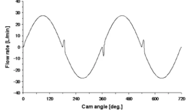
Numerical analysis uses eqn(1) until the cylinder approaches the notch and uses both eqn(1) and eqn(2) while cylinder passes over the notch. The pressure variation and the discharge flow rate is calculated using 4th-order Runge-Kutta method. Figure 2 shows the pressure variation in the cylinder for two cycles of rotation. The overshoot is observed at the bottom dead center where the flow direction changes from intake to discharge while the undershoot is observed at the top dead center where the flow direction changes from discharge to intake. Figure 3 shows the flow rate variation for two cycles of rotation. Reverse flow is observed near the top and bottom dead center due to the pressure difference between the cylinder and the port to the system. This reverse flow affects on the volumetric efficiency and is also observed in the experiment.
3. Experiment and Discussion
The pressure variation in the cylinder, the flow rate through the port, and the leakage considering the piston tilting are measured for the change in the discharge pressure, the rotational speed, and the viscosity of the working fluid. Figure 4 shows the schematic diagram of the test system and Photo 1 shows the experimental apparatus. A 5-HP induction motor is used with rpm controller and piezoelectric pressure transducers and T-type thermocouples are used to measure pressure in the cylinder and the temperature of the working fluid. An eccentric journal and ball bearing system is used to drive the piston back and forth and a timing belt is used to control the intake and discharge valve timing.
The power pack supplies fluid with constant pressure to the cylinder when the piston locates at the bottom dead center. As the motor is running the piston moves back and forth due to the cam assembly so that the discharge flow rate can be controlled by rotational speed of the motor. The leakage is measured using a small beaker with an electronic balance dp dθ --- K Vω --- dV dθ ---ω q– in+qout ⎝ ⎠ ⎛ ⎞ – = Q ∆PT ρ --- Q 2 2Cn2A2 ---– ⎝ ⎠ ⎜ ⎟ ⎛ ⎞ 1 a ---x1 x2
∫
⁄ dx =Fig. 1. Schematic diagram of the mathematical model for this study.
Fig. 2. Numerical result of pressure variation in the cylinder.
because its amount is not enough to measure directly. The relief pressure range of discharge port is set to 40~120 bar, rotational speed is set to 500~2,000 rpm, and the viscosity of working fluid is 100~180 cSt for the experimental temperature range.
The viscosity of the working fluid is very sensitive to the temperature change as shown in Fig. 5 so that it is very important to know the temperature of the working fluid in operation.
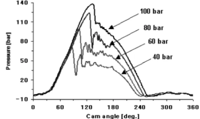
Figure 6 shows the pressure variation in the cylinder for the discharge pressure change. As the cam angle increases from 0,
the pressure increases with the piston movement but the reverse flow occurs as the discharge port opens because the pressure at the port to the system is already high enough. However, the cylinder pressure increases further as the cam angle increases to reach the relief pressure then, there is an overshoot in pressure as the cam angle is in the range of 90~120degrees. During the discharge process, the cylinder pressure becomes higher than the relief pressure due to the collision of discharge flow and the reverse flow from the system port. So the overshoot and the reverse flow increases as the relief pressure increases.
Fig. 4. Schematic diagram of the test system.
Photo 1. Experimental apparatus.
Fig. 5. Viscosity variation of working fluid with respect to the temperature change.
Fig. 6. Pressure variation in the cylinder w.r.t. the discharge pressure (Ps=1 bar, ω=1,500 rpm, µ0=180 cSt).
Fig. 7. Pressure variation in the cylinder w.r.t. the suction pressure (Pd= 60 bar, ω = 1,000 rpm, µ0= 180 cSt).
Fig. 8. Pressure variation in the cylinder w.r.t. the motor speed (Pd= 60 bar, Ps=1 bar, µ0= 180 cSt).
Figure 7 shows the pressure variation in the cylinder for the intake pressure change. The pressure variation in discharging process is almost same if the discharge pressure is kept same but the pressure variation in suction process depends on the intake pressure setting.
However, the reverse flow rate decreases as the intake pressure increases which results in large effect in volumetric efficiency.
Figure 8 shows the effect of motor speed. As the motor speed increases, pressure rising is delayed at the beginning and the undershoot in suction pressure is observed near the top dead center where the flow direction changes from discharge to intake. This is due to the cavitation at high speed and results in decreasing the volumetric efficiency as the discharge rate increases.
Figure 9 shows the effect of the viscosity of the working fluid. The temperature change is not so large during the experiment so as the viscosity change. The pressure peak doesn’t change much near the cam angle of 90degrees. However, the leakage flow increases as the viscosity decreases results in rapid pressure drop near the cam angle of 180degrees.
The discharge flow rate is measured for the change in motor speed, discharge pressure, and suction port pressure. Figure 10 shows the volumetric efficiency variation for the change in discharge pressure. As the discharge pressure increases the volumetric efficiency decreases. One reason is that the
working fluid is not sucked well at the beginning of the suction process because of the remaining high pressure in the cylinder so that the discharge volume is reduced and the other reason is that the reverse flow increases as the discharge pressure increases. We can also observed in Fig. 6 that the duration of the suction process decreases as the discharge pressure increases.
Figure 11 shows the effect of the motor speed on volumetric efficiency. As the motor speed increases the volumetric efficiency decreases due to the cavitation at the suction port.
We can also see the similar effects in Fig. 8 that the undershoot in suction pressure is observed as the motor speed increases so that the increasing of pressure in the cylinder is delayed due to the cavitation in the cylinder at the beginning of
Fig. 9. Pressure variation in the cylinder w.r.t. the viscosity of fluid (Pd= 40 bar, Ps= 1 bar, ω =1,000 rpm).
Fig. 10. Volumetric efficiency variation w.r.t. the discharge pressure (Ps= 1 bar, ω = 1,500 rpm, µ0= 180 cSt).
Fig. 11. Volumetric efficiency variation w.r.t. the motor speed (Pd= 40 bar, Ps= 1 bar, µ0= 180 cSt).
Fig. 12. Discharge rate variation w.r.t. the suction pressure (Pd= 40 bar, ω = 1,000 rpm, µ0= 140 cSt).
Fig. 13. Volumetric efficiency variation w.r.t. the suction pressure (Pd= 40 bar, ω = 1,000 rpm, µ0= 140 cSt).
the discharging process.
Figures 12 and 13 show the effects of suction pressure on the discharge flow rate and volumetric efficiency. The suction pressures of 1bar and 10bar are set by adjusting the relief pressure of power pack. When the motor speed is low, the volumetric efficiency increases from 90% when the suction pressure is set to 1bar but it reaches almost 100% when the suction pressure is increased to 10bar. However, the volumetric efficiency decreases due to the cavitation despite the high suction pressure when the motor speed increases more than 1,500 rpm. So, the volumetric efficiency increases 10% for the increase in suction pressure from 1bar to 10bar in overall.
The leakage is measured for the change in motor speed, discharge pressure, and viscosity of fluid. Figure 14 shows the leakage variation for the discharge pressure change. The leakage is proportional to the pressure difference so that it increases as the discharge pressure increases.
Figure 15 represents the leakage variation with respect to the motor speed. When the discharge pressure and the clearance between cylinder and piston are kept constant, the leakage increases as the motor speed increases. But the leakage is not doubled as the motor speed is doubled because the fluid is not sucked into the cylinder well as the motor speed increases due to the cavitation as shown in Fig. 11.
The piston of a bent axis type pump cannot move following the cylinder axis due to its structural problem. So, there must be the tilting between the piston motion and the cylinder axis. Figures 16 and 17 show the leakage variation for the change in discharge pressure and the motor speed when the tiling is considered. The leakage is doubled when the tilting is 3degrees compared to the case when the tiling is 0. The reason is that the tilting makes the clearance larger so that the flow area increases. It results in increasing leakage even though the pressure difference is same.
4. Conclusions
In this study, the pressure in the cylinder and the discharge flow rate variation are computed numerically for the bent axis type piston pump. Numerical results are compared with the experimental results. The results of this study are summarized as follows; It is observed that there is an overshoot in pressure at the beginning of the discharging process and an undershoot in pressure at the beginning of the suction process through the analysis considering the inertia of the working fluid. These phenomena are caused by the reverse flow as discussed in the experiment.
The volumetric efficiency decreases as either the discharge pressure or the motor speed increases. It is due to the reverse flow and cavitation caused by the pressure difference between the cylinder and the discharge port to the system.
The volumetric efficiency can be increased by increasing the suction pressure so as to suppress the cavitation and the reverse
Fig. 14. Leakage flow variation w.r.t. the discharge pressure (Ps= 1 bar, ω = 1,000 rpm).
Fig. 15. Leakage flow variation w.r.t. the motor speed (Pd= 60 bar, Ps= 1 bar).
Fig. 16. Leakage flow variation w.r.t. the discharge pressure with tilting (Ps= 1 bar, ω =1,000 rpm).
Fig. 17. Leakage flow variation w.r.t. the motor speed with tilting (Pd= 60 bar, Ps= 1 bar).