1. INTRODUCTION
Nowadays, the number of harmonic producing loads have increased. In a DC traction system, rectifier substations are a major cause of harmonic distortion in the ac supply .In this paper, a statcom is applied, when the train is connected to line and it isn’t in brake mode, it can be as an active power filter to compensate reactive power and harmonics [1], [2], [3], and also when the train is in brake mode, it can operated as an inverter to convert the regenerative energy back into the ac power grid. In the past, the regenerative energy caused by decelerating trains or in brake mode was dissipated in resistor banks. In this paper, to reduce cost in a DC traction system, the regenerative energy is converted back into the ac supply [4], [5].
2. POWER SUPPLY DESCRIPTION
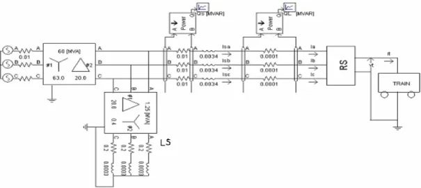
Fig.1 shows a part of a dc traction system. Consisting of a train, a rectifier substation and a lighting substation. The main transformer station has a 63kv/20kv transformer with λ/∆ connection. And the rectifiers substation (RS) has a 20kv/0.592kv/0.592kv transformer with λ/λ/∆ connection and
two rectifiers that are parallel (fig.2). Output of RS that is 750vdc is connected to the third rail. Lighting substation (LS) that is used to consumption of lighting, ventilation and so on in station, have a 20kv/400v transformer with λ/∆ connection.
Fig. 2 Rectifier substation.
Improvement of Power Quality in DC Traction Systems Using Statcom
Seyed Hossein Hosseini*, Mitra sarhangzadeh**, and Ali Ajami***
*
Azarbyjan Regional Electric Power Company, Tabriz, Iran.( Email: [email protected] )
** Tabriz Electric Power Distribution Company, Tabriz, Iran. ( Email: [email protected] )
***
Faculty of Electrical and Computer Engineering, University of Tabriz, Tabriz, Iran. (Email: [email protected])Abstract: In this paper a statcom is developed to improve the power quality in a dc traction system. The proposed statcom can be
used as both inverter and active filter. As an active filter , it can compensate harmonic distortion and reactive power and as an inverter, it can recycle regenerative energy caused by decelerating trains. The simulation results are carried out by using PSCAD/EMTDC software.
Keywords: Power quality, DC traction system, Statcom, PSCAD/EMTDC.
3. ELECTRIC TRAIN MODEL
Each wagon has four 750vdc motors. Motors have the following series parallel combinations:
• All motors are in series with each other.
• Two motors in series are paralleled with two other motors in series.
• All the four motors in series with each other but their field direction is reversed so that they act as a generator.
Then a typical speed-time curve that is shown in fig.3, can be divided into the following segments:
• oa: During this period the load is accelerated from rest.
• ab: Free running period during which the train runs at constant speed with constant torque and horse power input.
• bc: Breakers are applied to bring the train to a stop at the next station.
Fig. 3 Speed-time curve.
In the past, in a DC traction system, when train was in generator mode, the regenerative energy is dissipated in the resistor banks (fig.4).
Fig. 4 DC motor with resistor bank.
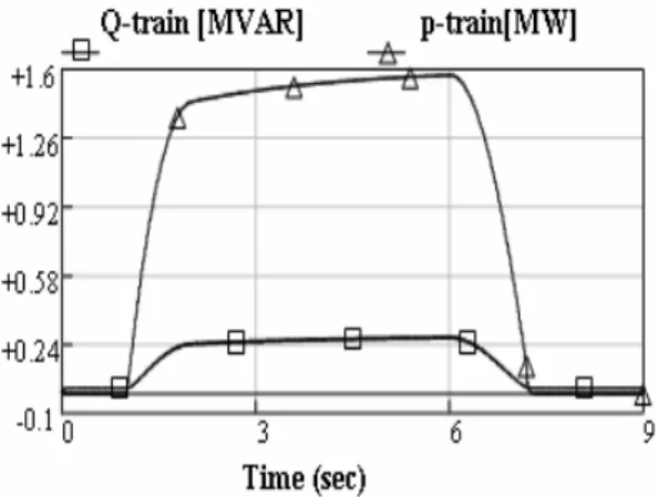
As fig.5 shows direct current of third rail is zero (at 7.2sec), when train is in regenerative mode. Load reactive and active powers are shown in fig.6. Fig.7 shows the Current and Voltage at ac network that current has harmonics.
Fig. 5 DC bus current without statcom.
Fig. 6 Active and Reactive power without statcom.
Fig. 7 Power supply current and voltage without statcom.
4. STATCOM TOPOLOGY
Power electronics appliances are used widely in industrial, commercial and consumer environment. This appliances generate harmonic and reactive current in the utility system that cause EMI pollution to other loads in the system. APF have been widely used in distribution power networks to improve power quality. Shunt active power filter purpose is to cancel the load current harmonics fed to the supply. It can also contribute to reactive power compensation and balancing of three-phase currents. In an active power filter, a controller determines the harmonics that are to be eliminated and also the reactive power that is to be compensated. The output of this controller is the reference of a three-phase current controlled inverter. Fig.8 illustrates the principle of a shunt active filter that will be used in dc traction. The reference currents are calculated from several methods such as:
1. Synchronous reference method. 2. pq method.
3. Modified pq method.
4. Instantaneous active and reactive current component method.
In this paper the modified pq method is used and also to reduce the low-order harmonic content of the statcom output, hysteresis current control is applied.
Fig. 8 Statcom topology.
5. MODIFIED PQ METHOD
The compensating reference currents with modified pq method are [1], [2], [3]:
⎥
⎥
⎦
⎤
⎢
⎢
⎣
⎡
⎥
⎥
⎥
⎦
⎤
⎢
⎢
⎢
⎣
⎡
⎥
⎥
⎦
⎤
⎢
⎢
⎣
⎡
− ∆ = LQ
os L P v v v v f i f i 1 ( ) α β β α β α(1)
2
2
β
α
v
v
+
=
∆
(2)
In this paper, PI controller is used to have constant voltage in the dc bus. Output of controller is multiplied by capacitor current to calculate Pc losses. This power is added to compensated active power, then the compensating reference
currents are:
⎥
⎥
⎦
⎤
⎢
⎢
⎣
⎡
⎥
⎥
⎥
⎦
⎤
⎢
⎢
⎢
⎣
⎡
⎥
⎥
⎦
⎤
⎢
⎢
⎣
⎡
− + ∆ = LQ
Pc os L P v v v v f i f i 1 ( ) α β β α β α(3)
When train is in brake mode, the regenerative energy will be converted back into the ac power grid that can provide
a part of
the lighting substation current and its amplitude depends
on regenerative dc current.
6. SIMULATION RESULTS
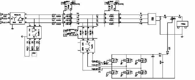
The simulation results are carried out by using PSCAD/EMTDC software. In this paper, resistor banks is removed and the regenerative energy are converted back into the ac network with a diode that is connected between dc bus and statcom (fig.9)[4],[5]. The dc current waveform is given in fig.10 and diode current is shown in fig.11 that has regenerative current. The current waveform drawn by the proposed load after compensation is illustrated in fig.12. Harmonic spectrums of current show 11th and 13th components are companseted with
Statcom( Figures 13 and 14).
Fig. 10 DC bus current with statcom.
Fig. 12 Power supply current and voltage with statcom.
Fig. 13 Harmonic spectrum of current without statcom.
Fig. 14 Harmonic spectrum of current with statcom. Assuming that we show the points of network as in fig.15, Figures 16 and 17 show active and reactive powers of train (P-train, Q-train), connecting point of statcom and train (Ps, Qs) and statcom (Pf, Qf). When train is in generator mode, Q-train is zero and Qf is equal to Qs. This means that regenerative energy converted back in to the ac network and fig.18 shows current waveform of inverter mode.
Fig. 15 Harmonic spectrum of current with statcom.
Fig. 16 Active powers of Train (p-train),Statcom (pf) and connecting point of statcom and train (ps) with statcom.
Fig.17 Reactive powers of Train (Q-train),Statcom (Qf) and connecting point of statcom and train (Qs) with statcom.
Fig. 18 Regenerative current in brake mode. Figures 19 and 20 show active and reactive powers of Main station (p-fs, Q-fs), Lighting station (p-station, Q-station) and connecting point of statcom and train (ps, Qs) with statcom. When train is in brake mode, the regenerative energy back into the Lighting substation.
Fig. 19 Active powers of Main station (p-fs), Lighting station (p-station) and connecting point of statcom and train (ps) with
Fig.20 Reactive powers of Main station (Q-fs), Lighting station (Q-station) and connecting point of statcom and train (Qs) with
statcom.
7. CONCLUSION
In this paper a statcom is applied for power quality improvement in a DC traction system. The proposed statcom can be considered as an active filter to compensate reactive power and harmonics and also as an inverter to covert the regenerative energy back into the ac grid, when the train is in brake mode. The proposed method will reduce the costs in DC traction systems.
8. REFERENCES
[1] Fang Zheng Peng; Ott, G.W., Jr.; Adams, D.J, “Harmonic and reactive power compensation based on the generalized instantaneous reactive power theory for three-phase four-wire systems,” IEEE Transactions on Power Electronics, Nov. 1998, Vol. 136, pp. 1174-1181.
[2] Marques, G.D. Industrial Electronics Society, "A comparison of active power filter control methods in unbalanced and non-sinusoidal conditions,” IECON '98. Proceedings of the 24th Annual Conference of the IEEE Published: 1998 Vol.1, pp. 444-449.
[3] Soares, V.; Verdelho, P.; Marques, G.D , “An instantaneous active and reactive current component method for active filters,” IEEE Transactions on Power Electronics, July1998 Vol. 154, pp. 660-669.
[4] Horn, A.; Wilkinson, R.H.; Enslin, T.H.R,”Evaluation of converter topologies for improved power quality in DC traction substations,” ISIE '96, Proceedings of the IEEE International Symposium on Industrial Electronics, 1996, Vol. 2, pp. 802-807.
[5] Yii Shen Tzeng; Ruay-Nan Wu,”Electric network solutions of DC transit systems with inverting substations,” IEEE Transactions on Vehicular Technology , Nov. 1998, Vol. 474, pp. 1405-1412.