P1-80 / Y.-H. Kim
IMID 2009 DIGEST •
Abstract
High contrast red, green and blue organic light-emitting diodes were fabricated using inorganic metal multi layer composed of thin Al, KCl and thick Al and then were compared to optical and electrical characteristics with the attached polarizer and conventional OLEDs. Ambient light reflection of OLED using inorganic metal layer, polarizer and conventional metal layer were 29.2, 31.1 and 82.5% respectively. Optical characteristics of OLEDs using inorganic metal layer were max luminescence of 13040 cd/m2 and luminous efficiency of 2.12 cd/A at 8V whereas OLEDs using polarizer has 8456 cd/m2 and 1.43 cd/A at 8V each. OLEDs including inorganic metal multi layers show significant technical advantages in achieving high performance of OLED display with improved contrast ratio of 251:1, specifically in Red OLED.
1. Introduction
Light-emitting devices (OLEDs) have become increasingly a subject of interest in recent years, and numerous works have been devoted to the improvements of external quantum efficiency [1] and reliability [2]. The growing interest is largely motivated by its potential application in flat panel displays. In a conventional OLED, the reflective metal layer benefits the out coupling efficiency because the back emission from organic material is also reflected forward. Concurrently, such OLEDs have the drawback of low display contrast due to the reflection
of ambient light by the highly reflective cathode; however, high contrast between an image and the ambient reflections is essential for all display applications. This problem becomes particularly significant for outdoor display applications under strong ambient light.
Low ambient light reflectivity can be achieved by using circular polarizers [3], light-absorbing layers [4] and optical interference layers [5], etc. Among them, structure with optical interference layer is considered as a good approach to balance the device performance and fabrication simplicity [6], which is crucial for mass production. This structure consists of a thin semitransparent metal layer, inorganic light transition layer and a thick reflective metal layer. Low reflection is realized by the cancellation (destructive optical interference) of two reflected light waves, one from the front thin metal layer and another with π phase difference from the rear thick metal layer. In this paper, the optical and electrical characteristics of inorganic metal multi-layered OLED were observed and compared with conventional OLEDs with polarizer.
2. Experimental
ITO coated glass was cleaned in ultrasonic bath by regular sequence: in acetone, methanol, diluted water and isopropyl alcohol. Hereafter, pre-cleaned ITO was treated by O2 plasma under condition of 2ⅹ10-2 Torr,
High Contrast Red, Green, and Blue Organic
Light-emitting Diodes using Inorganic Metal Multi Layers
You-Hyun Kim
1, Sang Youn Lee
2, Wook Song
1, Mei Mong
1and
Woo Young Kim*
1, 31School of Display Engineering, Hoseo Univeristy, Beabang-Eup Asan-City, Chungnam,
336-795 South Korea
Tel.:82-41-540-5944, E-mail: [email protected]
2Semiconductor Display Engineering, Hoseo Univeristy, Beabang-Eup Asan-City, Chungnam, 336-795 South Korea
3display Technology Incubation Center, Hoseo University, Beabang-Eup Asan-City,
Chungnam 336-794 South Korea
P1-80 / Y.-H. Kim
• IMID 2009 DIGEST
125W during 2 minutes [7]. High contrast OLEDs were fabricated using the high vacuum (1.0ⅹ10-7
Torr) thermal evaporation and NPB as hole transport layer, Alq3 as electron transport layer, LiF as electron
injection layer, thin Al, KCl, and thick Al as inorganic metal multi layers were deposited by 1, 1, 0.1, 0.5, 0.5, and 5 Å/s, respectively.
(a) (b) (c)
Figure 1. OLED devices with (a) inorganic metal multi layer, (b) polarizer attached, (c) conventional metal layer.
(a) (b)
(c)
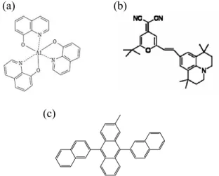
Figure 2. Molecular structures of organic materials in OLEDs (a) Alq3 (b) DCJTB (c)MADN
Fig. 1 shows the schematic configuration of the high contrast RGB OLED using inorganic metal multi layer, RGB OLED using polarizer, and RGB OLED control device in this study, and Fig. 2 shows the molecular structures of the chromophores in the devices as organic emitting layer materials. The inorganic metal multi layer red, green, and blue OLED emissive materials were as follows: Alq3:DCJTB-0.4%, Alq3, MADN, respectively. Three kinds of RGB devices were fabricated using inorganic metal multi layer, polarizer, and conventional metal layer. Contrast measurement of OLEDs with ambient lights was determined by extrinsic reflection of fabricated OLEDs with measured reflection ambient light of control device with OLYMPUS BX51 and
TOPCON BM-7, respectively. With various DC voltage bias, the optical and electrical properties of high contrast OLEDs such as the current density, luminance, luminous efficiency, Commission Internationale de L’eclairage (CIExy) coordinates and electroluminescence characteristics were measured with Keithley 236, LMS PR-650, respectively. Electroluminescence spectra were observed with LMS PR-650.
3. Results and discussion
Table 1 describes the structures of fabricated OLEDs. Device A used inorganic metal multi layers such as thin Al (70 Å) / KCl (300 Å) / thick Al (1000Å) with red, green, and blue OLEDs of functional layers of NPB (700 Å) / Alq3:DCJTB-0.4% (200Å), Alq3(200 Å), and MADN (200 Å) / Alq3 (300 Å) / LiF (10 Å) whereas devices B and C were polarizer-attached, using conventional OLED devices with bare metal electrode layer with the same red, green and blue emitting layer each.
TABLE 1. Three kinds of IMML, polarizer attached, and normal RGB devices
Device A
NPB (700 Å) / RGB(200 Å ) / LiF (10 Å) / Al(70 Å) / KCl(300 Å) / Al(1000 Å)
Device B Polarizer / NPB (700 Å) / RGB(200 Å ) / LiF (10 Å) / Al(1000 Å)
Device C NPB (700 Å) / RGB(200 Å ) / LiF (10 Å) / Al(1000 Å)
All illustrations should be clearly displayed by leaving at least a single line of spacing above and below them. When placing a figure at the top of a page, the top of the figure should be at the same level. At the last page of the manuscript, make sure that the columns have the same length as shown in this template.
OLEDs’ reflectance characteristics under ambient light are shown in Figure 3. Average reflectance of RBG devices A, B and C in the region from 400 to 700 nm was 29.2, 31.8, and 82.5 %, respectively. This result implies that inorganic metal multi layers show low reflectance under ambient light and are able to obtain high contrast OLED devices without polarizer.
P1-80 / Y.-H. Kim
IMID 2009 DIGEST • Luminescence characteristics with various current
densities of OLEDs are described in Figure 4. Device A, B, and C of fabricated OLEDs using inorganic metal multi layer showed luminance of 2803, 3897, and 1283 cd/m2 at current density of 120, 211, and 130 mA/cm2, respectively whereas OLED devices using polarizer had luminance of 1925, 2502, and 916 cd/m2 at current density of 138, 241, and 158 mA/cm2,
respectively. This result indicates that inorganic metal multi-layered OLEDs will be expected to achieve higher efficiency and longer lifetime than polarizer-attached OLEDs because luminescence of devices
using inorganic metal multi layers was higher than that of polarizer attached OLEDs under the same current density.
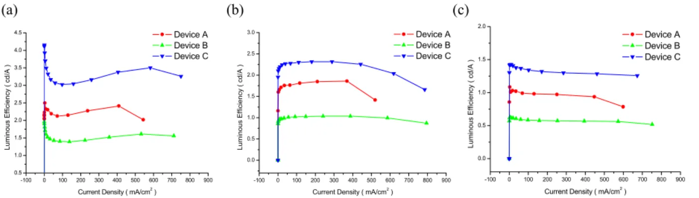
As shown in Figure 5, luminous efficiency of red, green and blue OLEDs with inorganic metal multi layer such as 2.12, 1.81 and 0.99 cd/A is higher than that of OLEDs with polarizer or bare metal layer such as 1.43, 1.09 and 0.57 cd/A. Contrast ratio of inorganic metal multi layer OLEDs with red emission was 251:1, which is better than that of polarizer attached red OLEDs of 186:1 based upon the brightness of the room and the contrast ratio
400 450 500 550 600 650 700 750 10 20 30 40 50 60 70 80 90 Device A Device B Device C R e fle cta nc e ( % ) Wavelength ( nm ) 400 450 500 550 600 650 700 750 10 20 30 40 50 60 70 80 90 100 Device A Device B Device C Re flect ance ( % ) Wavelength ( nm ) 400 450 500 550 600 650 700 750 10 20 30 40 50 60 70 80 90 100 Device A Device B Device C Re flect ance ( % ) Wavelength ( nm )
Fig. 3. Reflectance characteristics of OLEDs with inorganic metal multi layer, polarizer and bare metal layer under ambient light in 400~600 nm (a) red OLEDs (b) green OLEDs (c) blue OLEDs
(a) (b) (c)
Fig. 4. Luminescence characteristics with various current densities of OLEDs (a) red OLEDs (b) green OLEDs (c) blue OLEDs with inorganic metal multi layer, polarizer and bare metal layer.
(a) (b) (c) -100 0 100 200 300 400 500 600 700 800 900 0 5000 10000 15000 20000 25000 Device A Device B Device C Lu m ino us ( c d/ m 2 )
Current Density ( mA/cm2 )
-100 0 100 200 300 400 500 600 700 800 0 2000 4000 6000 8000 10000 12000 14000 Device A Device B Device C Lu m ino us ( c d/ m 2 )
Current Density ( mA/cm2 )
-100 0 100 200 300 400 500 600 700 800 0 2000 4000 6000 8000 10000 Device A Device B Device C Lu m ino us ( c d/ m 2 )
Current Density ( mA/cm2 )
Fig. 5. Luminous efficiency of (a) red, (b) green and (c) blue OLED devices with inorganic metal multi layer, polarizer and bare metal layer.
(a) (b) (c) -100 0 100 200 300 400 500 600 700 800 900 0.5 1.0 1.5 2.0 2.5 3.0 3.5 4.0 4.5 Device A Device B Device C Luminous E ffi ci ency ( c d /A )
Current Density ( mA/cm2
) -100 0 100 200 300 400 500 600 700 800 900 0.0 0.5 1.0 1.5 2.0 2.5 3.0 Device A Device B Device C Lumi nous E ffi ci e nc y ( c d/ A )
Current Density ( mA/cm2
) -100 0 100 200 300 400 500 600 700 800 900 0.0 0.5 1.0 1.5 2.0 Device A Device B Device C L u m in ou s E fficie ncy ( cd /A )
P1-80 / Y.-H. Kim
• IMID 2009 DIGEST calculated by the equation below
Luminescenceon + Reflected ambient light
Contrast ratio =
Luminescenceoff + Reflected ambient light
These results suggest inorganic metal multi layer OLEDs will eventually obtain better performance than polarizer-attached OLEDs in brightness, luminous efficiency, contrast ratio and lifetime.
4. Summary
Inorganic metal multi layer OLEDs show possibility of high contrast ratio, high luminescence, high efficiency, and longer lifetime according to ambient light’s optical interference comparing with polarizer-attached OLEDs. OLEDs with polarizer film preventing ambient light have several technical problems such as the higher cost of polarizer and additional expenses in manufacturing processes. Inorganic metal multi layer can solve these issues via less reflectance performance, compatible thin film process and lower material cost of metals and inorganic materials. Therefore, OLEDs using inorganic metal multi layers have significant advantages of low cost and high yield production as well as high performance of OLED display with improved contrast ratio.
Acknowledgement
This research was supported by a grant (F0004141-2008-31) from Information Display R&D Center, one of the 21st Century Frontier R&D Programs funded by
the Ministry of Knowledge Economy of Korean government
5. References
1. Y. Cao, I. D. Parker, G. Yu, C. Zhang, and A. J. Heeger, Nature _London 397, 414 (1999).
2. H. Aziz, Z. D. Popovic, N. X. Hu, A. M. Hor, and G. Xu, Science 283, 1900 (1999).
3. V. Vaenkatesan, R. T. Wegh, J. P. Teunissen, J. Lub, C. W. M. Bastiaansen, and D. J. Broer, Adv. Funct. Mater. 15, 138 (2005).
4. H. Aziz, Y. F. Liew, H. M. Grandin, and Z. D. Popovic, Appl. Phys. Lett. 83, 186 (2003).
5. Z. Y. Xie and L. S. Hung, Appl. Phys. Lett. 84, 1207 (2004).
6. X. D. Feng, R. Khangura, and Z. H. Lu, Appl. Phys. Lett. 85, 497 (2004).
7. C. C. Wu, J. C. Sturm and A. Khan, Appl. Phys. Lett. 70,1348 (1997).