682
-Abstract - A 12/14 bearingless switched reluctance motor (BLSRM) with hybrid stator poles has been proposed due to the outstanding decoupling characteristics between the torque and suspending force. However, the motor is a two-phase motor. The output torque of the motor has torque dead zone and high torque ripple. Hence, the motor cannot self-start at some rotor positions. To solve the self-starting problems and reduce the torque ripple, a stepped rotor is proposed in this paper. Then, the motor with the stepped rotor is optimally designed. In the new designed motor, the majority parameters are kept the same with those of original motor; only the torque pole arc and rotor pole shape are optimally designed. The characteristics of the redesigned motor, such as inductance, torque and suspending force, are analyzed and compared with those in the original motor. Finally, the effectiveness of the proposed method is verified by the simulation results.1. Introduction
Many modern industrial applications, such as high speed machine tools, turbo-molecular pumps, centrifugal pumps, compressors, flywheel energy storage and aerospace applications need high speed or ultra-high speed motors [1]. However, the motors with traditional mechanical bearings may cause thermal problems, heavy wear and increased frictional drag in high speed applications, which may not satisfy the requirement of modern industrial field.
Bearingless switched reluctance motor (BLSRM) is developed on the basis of magnetic bearing motor (MBM) and switched reluctance motor (SRM). Hence, BLSRM not only has advantages of magnetic bearing motor, such as compact size, low cost and high power density [2], but also inherits high-speed performance and adaptability to harsh environment of SRM. Hence, BLSRM can achieve the operation in high speed or ultra high speed applications.
Recently, several structures of BLSRM have been proposed [2]-[8]. Although these structures, such as 12/8 double winding type [2]-[3], 12/8 single winding type [4]-[5], 8/6 single winding type [6]-[7] and Morrison rotor type [8], can realize stable suspension with the rotor standstill or rotating. However, all the motors are based on general SRM structure, the range of the available suspending force is limited, and the torque control is coupled with the suspending force control. What’s more, to realize stable suspension, the complex mathematical equations have to be derived.
In order to expand the available suspending force region and reduce the control difficulty of conventional BLSRMs, the 12/14 hybrid stator pole type BLSRM is proposed [1]. The 12/14 BLSRM has 8-torque poles and 4-suspending force poles in the stator. The air-gap can be controlled through the force generated by the windings on the 4-suspending force poles. Compared with conventional BLSRMs, the suspending force performance is much improved and the air-gap is easier to control. However, the motor is operated as a two-phase SRM, so the output torque has torque dead zone and high torque ripple. That is, the motor cannot self-start at some rotor positions.
In this paper, a stepped rotor is proposed to solve the self-starting and high torque ripple problems in the 12/14 hybrid stator pole type BLSRM. The optimized design process for the redesigned motor, including pole arc selection and stepped height selection is introduced in detail. The characteristics of the redesigned motor are analyzed by the software finite element method magnetics (FEMM) and compared
with that of original type. Finally, the simulation and comparison results are presented to verify the validity of the proposed method.
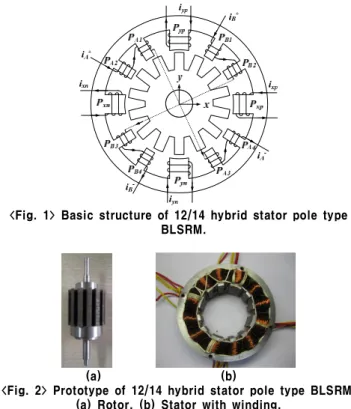
2. Analysis of 12/14 Hybrid Stator Pole Type BLSRM A 12/14 hybrid stator pole type BLSRM is presented in [1]. Unlike conventional BLSRMs, the structure has separated torque and suspending force poles. Furthermore, short flux paths are taken and no flux reversal exists in the stator. Fig. 1 shows the basic structure of 12/14 hybrid stator pole type BLSRM. Windings on the torque poles PA1, PA2, PA3 and PA4 are connected in series to construct
phase A, and windings on the torque poles PB1,PB2,PB3and PB4are
connected in series to construct phase B. The windings on the suspending force poles Pxp, Pxn, Pyp and Pyn are independently
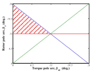
controlled to construct four suspending forces in the x- and y-directions. Meanwhile, to get the continuous suspending force, the suspending force pole arc is selected not to be less than one-rotor pole pitch. Fig. 2 shows the prototype of the 12/14 hybrid stator pole type BLSRM.
<Fig. 1> Basic structure of 12/14 hybrid stator pole type BLSRM.
(a) (b)
<Fig. 2> Prototype of 12/14 hybrid stator pole type BLSRM. (a) Rotor. (b) Stator with winding.
Fig. 3 shows the torque characteristics of the 12/14 hybrid stator pole type BLSRM. As shown in Fig. 3, the output torque of the BLSRM has torque dead zone and high torque ripple. In the torque dead zone, the motor cannot produce enough starting torque, so the motor cannot self-start in this region. Furthermore, due to these inherent toque dead zones, the torque ripple is impossible to be reduced regardless of any control algorithm.
자기기동 및 토크리플 저감을 위한 12/14 베어링리스 SRM의 설계 및 특성해석
서진요*, 이동희*, 안영주**, 안진우*
경성대*, 부경대**
Analysis and Design of 12/14 Bearingless Switched Reluctance Motor
for Self-Starting and Torque Ripple Reduction
Zhenyao Xu*, Dong-Hee Lee*, Young-Ju An**, Jin-Woo Ahn*
Kyungsung University*, Pukyong National University**
683
-0 6.5 13 19.5 26 0 0.05 0.1 0.15 0.2 0.25Rotor Position (deg.)
T o r q u e ( N .m ) Phase A Phase B
<Fig. 3> Torque characteristics of 12/14 hybrid stator pole type BLSRM.
3. Design of 12/14 Hybrid Stator Pole Type BLSRM with Stepped Rotor
In order to reduce the torque ripple and solve the self-starting problems, the 12/14 BLSRM is redesigned and a stepped rotor is employed in the structure. The majority parameters in the redesigned motor are kept the same with that of the original motor, only the torque pole arc of the stator and pole shape of the rotor are optimally designed.
3.1 Selection of Pole Arc
Fig. 4 shows the main parameters of the redesigned BLSRM. In Fig. 4, βsfis the suspending force pole arc, βstis the torque pole arc,
βr is the rotor pole arc, βsr is the stepped angle of the stepped rotor,
and hsris the stepped height of the stepped rotor.
<Fig. 4> Parameters in the redesigned BLSRM. To solve the self-starting problems, reduce the torque ripple, and keep the torque generation capacity not much reduced, the pole arcs of the motor have to satisfy the following requirement:
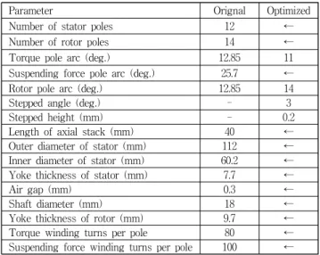
o o o 85 . 12 14 2 360 360 » ´ = > r r qN b (1) o o o 7 . 25 14 360 360 » = £ + r r st N b b (2) r st b b < (3)
where, q is the number of motor phase, Nr is the number of rotor
poles. From (1), (2) and (3), the available value range of the torque and rotor pole arcs can be confirmed as shown in the shadow area of Fig. 5. According to Fig 5, three groups of the torque and rotor pole arc combination, 12°/13.5°, 11°/14°, 10°/14.5°, are chosen for optimally designing. TABLE 1, 2 and 3 show the torque characteristics of the motor with fixed stepped height 0.2mm and various stepped angle when the torque and rotor pole arc combinations are 12°/13.5°, 11°/14° and 10°/14.5°, respectively.
To choose the optimized torque and rotor pole arc combination, the starting torque, maximum torque, minimum torque, average torque and torque ripple are considered in the comparison. From the comparison results, it can be found that the torque pole arc 11°, rotor pole arc 14°, and the stepped angle 3° is the optimized combination because it has lower torque ripple, larger starting torque and higher torque output capacity.
3.2 Selection of Stepped Height
If ignoring the effect of saturation, the inductance in SRM can be explained as, 0 6.5 13 19.5 26 0 6.5 13 19.5 26
Torque pole arc, bst (deg.)
R o to r p o le a r c , br ( d e g .)
<Fig. 5> Available value range for the torque pole arc βst
and rotor pole arc βr.
<Table 1> Torque characteristics with the torque pole arc 12°and rotor pole arc 13.5
<Table 2> Torque characteristics with the torque pole arc 11°and rotor pole arc 14°
<Table 3> Torque characteristics with the torque pole arc 10°and rotor pole arc 14.5°
(
o fr)
stk r r K g R L N g A N L=mm =mm q + 2 0 2 0 (4) in which, μ0 is the permeability of vacuum, μr is the relativepermeability, N is the number of turns, Lstkis the stack length, R is
the rotor radius, g is the air gap length, θo is the overlapped angle,
Kfr is a constant for the fringing inductance. From (4), it can be seen
that the inductance L is inversely proportional to the air-gap. That is, the slope of the inductance can be easily affected by the air-gap. Thereby, the torque characteristics may be affected.
Fig. 6 shows the torque characteristics of the redesigned motor with the stepped height changing from 0.1mm to 0.5mm while the torque pole arc, rotor pole arc and stepped angle are 11°, 14°, and 3°, respectively. The comparison results show that the stepped height 0.2mm is the best choice for the redesigned motor.
1 2 3 4 5 0 0.05 0.1 0.15 0.2 0.25 1 2 3 4 5 80 90 100 110 120 130
Tst Tmax Tmin Tav Tripple
<Fig. 6> Torque characteristics with variant stepped height. Stepped angle 1.5° 2.5° 3.5° 4.5° 5.5° Starting torque (N.m) 0.0442 0.0277 0.0241 0.0232 0.0227 Max. torque (N.m) 0.2049 0.2060 0.2068 0.2073 0.2066 Min. torque (N.m) 0 0.0068 0.0066 0.0065 0.0064 Average torque (N.m) 0.1691 0.1632 0.1564 0.1500 0.1433 Torque ripple (%) 121.17 122.06 128.03 133.84 139.67 Stepped angle 2° 3° 4° 5° 6° Starting torque (N.m) 0.0977 0.0828 0.0787 0.0775 0.0773 Max. torque (N.m) 0.2078 0.2085 0.2100 0.2104 0.2091 Min. torque (N.m) 0.0271 0.0458 0.0474 0.0472 0.0468 Average torque (N.m) 0.1614 0.1587 0.1522 0.1455 0.1387 Torque ripple (%) 111.96 102.52 106.83 112.16 117.02 Stepped angle 2.5° 3.5° 4.5° 5.5° 6.5° Starting torque (N.m) 0.1175 0.1022 0.0989 0.0968 0.0960 Max. torque (N.m) 0.2106 0.2123 0.2116 0.2111 0.2027 Min. torque (N.m) 0.0328 0.0513 0.0662 0.0684 0.0690 Average torque (N.m) 0.1483 0.1480 0.1445 0.1377 0.1307 Torque ripple (%) 119.89 108.78 100.62 103.63 102.30
684
-4. Characteristics of the Optimized 12/14 Hybrid Stator Pole TypeBLSRM
In order to verify the validity of the proposed stepped rotor, the software FEMM is employed to get the characteristics of the optimized motor, including inductance, torque and suspending force. Meanwhile, the original motor is also analyzed for comparison. TABLE 4 shows the dimensions of the two types of motors. <Table 4> Dimensions of original and optimized BLSRM
4.1 Inductance Characteristics
Fig. 7 (a) shows the inductance profiles of the torque windings with the same current of 2A in the original and optimized BLSRMs. From (4) it can be seen that the inductance is proportional to the overlap area between the torque and rotor poles and inversely proportional to the air gap. Since the overlap area between the torque and rotor poles is a function of the rotor position, the inductance changes obviously with the rotor position in both BLSRMs. Compared with original BLSRM, the inductance in the optimized motor is slightly smaller due to the reduced torque pole arc and stepped height at the beginning of the stepped rotor poles. However, the inductance rising region of the redesigned motor is increased. That is, the positive torque generation region is increased which is beneficial for solving the self-starting problem and reducing the torque ripple.
Fig. 7 (b) shows the inductance profiles of the suspending force windings with the same current of 2A in the two types. Unlike the inductance of the torque winding, the inductance characteristic of the suspending force winding changes slightly for different rotor positions with the same phase current in the two types. This is because the overlap area between the suspending force pole and rotor pole is always the same when the rotor rotates. Nevertheless, the inductance in the optimized motor is a little smaller than that in the original type due to the reduced air gap at the beginning of the stepped rotor poles. 0 13 26 39 52 0.01 0.015 0.02 0.025 0.03 0.035
Rotor Position (deg.)
In d u c ta n c e ( H ) Original Optimized 0 13 26 39 52 0.01 0.011 0.012 0.013 0.014 0.015
Rotor Position (deg.)
In d u c ta n c e ( H ) Original Optimized (a) (b)
<Fig. 7> Inductance characteristics. (a) Torque windings. (b)Suspending force windings
4.2 Torque and Suspending Force Characteristics
As is generally known, the torque of SRM is proportional to the square of the current and the rate of change of inductance with respect to rotor position. Fig. 8 (a) shows the continuous torque profiles of the torque windings with the same current 2A in the two
types. Compared with original motor, the starting torque is much increased and the torque ripple is also reduced in the optimized BLSRM, which satisfies the objective of the design.
Fig. 8 (b) shows the force comparison in the original and optimized BLSRMs. In the two types, the windings on the suspending force pole Pyp are excited. As shown in Fig. 8 (b), as the current is
constant, the suspending force has excellent linearity according to the rotor position in the two types, which is good for the rotor suspension control. However, the average force generated by the optimized BLSRM is a little reduced compared with that of the original motor due to the stepped rotor.
0 6.5 13 19.5 26 0 0.05 0.1 0.15 0.2 0.25
Rotor Position (deg.)
T o r q u e ( N .m ) Original Optimized 0 6.5 13 19.5 26 -25 0 25 50 75 100
Rotor Position (deg.)
F o r c e ( N ) Original Optimized (a) (b)
<Fig. 8> Comparison between the original and optimized BLSRMs. (a) Torque. (b) Suspending force.
5. Conclusions
In this paper, a stepped rotor is proposed to solve the self-starting problem in the original 12/14 hybrid stator pole type BLSRM. The motor with the stepped rotor is optimally designed. The design process is presented in detail. The characteristics of the optimally designed motor is analyzed. The simulation results show that the redesigned motor not only solves the self-starting problem, but also reduces the torque ripple. Furthermore, the decoupling characteristics is kept almost same with before, but the average output torque and suspending force is slightly reduced. Hence, a trade-off between self-starting and torque generation should be taken into account carefully in the design.
Acknowledgement
This work was supported by the Ministry of Education (MOE) through BK21 plus.
[References]
[1] Z. Y. Xu, F. G. Zhang, and J. W. Ahn, “Design and analysis of a novel 12/14 hybrid pole type bearingless switched reluctance motor,” in Proc. of 2012 IEEE International Symposium on Industrial Electronics (ISIE 2012), pp. 1922-1927.
[2] M. Takemoto, K. Shimada, A. Chiba, and T. Fukao, “A design and characteristics of switched reluctance type bearingless motors,” in Proc. 4th Int. Symp. Magnetic Suspension Technology, vol. NASA/CP-1998-207654, May 1998, pp. 49-63.
[3] M. Takemoto, H. Suzuki, A. Chiba, T. Fukao, and M. A. Rahman, “Improved analysis of a bearingless switched reluctance motor,” IEEE Trans. Ind. Application, vol. 37, no. 1, pp. 26-34, Jan./Feb. 2001. [4] W. T. Liu and S. M. Yang, “Modeling and control of a
self-bearing switched reluctance motor,” in Conf. Record of Fourtieth IAS Annual Meeting, Hong Kong, 2005, pp. 2720-2725. [5] F. C. Lin and S. M. Yang, “Self-bearing control of a switched
reluctance motor using sinusoidal currents,” IEEE Trans. Power Electronics., vol. 22, no. 6, pp. 2518-2526, 2007.
[6] L. Chen and W. Hofmann, “Analytically computing winding currents to generate torque and levitation force of a new bearingless switched reluctance motor,” in Proc.12th EPE-PEMC, Aug, 2006, pp. 1058-1063.
[7] L. Chen and W. Hofmann, “Speed regulation technique of one bearingless 8/6 switched reluctance motor with simpler single winding structure,” IEEE Transactions on Industrial Electronics, vol. 59, no. 6, pp. 2592-2600, June 2012.
[8] Carlos R. Morrison, Mark W. Siebert, and Eric J Ho, “Electromagnetic forces in a hybrid magnetic-bearing switched reluctance motor,” IEEE Trans. on Magnetics, vol.44, no.12, Dec. 2008.
Parameter Orignal Optimized
Number of stator poles 12 ←
Number of rotor poles 14 ←
Torque pole arc (deg.) 12.85 11 Suspending force pole arc (deg.) 25.7 ← Rotor pole arc (deg.) 12.85 14
Stepped angle (deg.) - 3
Stepped height (mm) - 0.2
Length of axial stack (mm) 40 ← Outer diameter of stator (mm) 112 ← Inner diameter of stator (mm) 60.2 ← Yoke thickness of stator (mm) 7.7 ←
Air gap (mm) 0.3 ←
Shaft diameter (mm) 18 ←
Yoke thickness of rotor (mm) 9.7 ← Torque winding turns per pole 80 ← Suspending force winding turns per pole 100 ←