1. INTRODUCTION Phase control converter has been using Thyristor for the switching device that can able to be control short circuit. There are uses for height voltage system but the mainly problem of them are harmonic distortion of output voltage and so many inputs current. For solution concern harmonic distortion in old day used fitter to adjust frequency for variable inductors reactance equation capacitor reactance.
This article presently technique of intervene firing method, comparisons with normally intervening firing that use passive filter. Technique of intervene firing at the 6-pulse phase-controlled converter.
We use this technique for drive DC motor. There were from obtained from the experiment was analyzed on the spectrum of the current voltage, harmonic distortion (THD).
Design of passive harmonic filter and technique of intervene firing method.
1. Find the apparent Power (KVA) and amplitude of voltage that using for drive load.
2. And then 3 = p S I V (1)
3. Compute impedance of system.
/ 3 =Vp Z I or / 3 =Vp Z I ( 2)
4. Compute the value of line reactance and should be have 3-5% of impedances system.
%XL=3% 5%( )− Z ( 3) 5. Compute inductance. 2 L f π = X L (4)
Computing factor of the passion harmonic filter consist of
1. Define any parameter of system that use for harmonic filter.
2. Define reactance power.
1 2
(tan tan ) com=k θ − θ
Q W ( 5)
com
Q Reactive power (kVAR) kW Real power(kW)
1
θ angle of old power factor
2
θ angle of new power factor
3. Analyze information harmonic current from exactly measurement or estimate and define number of filter.
4. Separate Qcom from follow the number of filter.
5. Define turning point of harmonic filter. 6. Define voltage of capacitor.
2 2 1 h Cr sys h n V V n ≥ × − (6) sys V voltage system h n turning value Cr V capacitor voltage
7. Define reactive power of capacitor that use.
2 2 2 1 Com Cr Sys h h Cr Q Q V n n V = ⎡ ⎤ ⎡ ⎤ × ⎢ − ⎥ ⎢ ⎥ ⎣ ⎦ ⎣ ⎦ ) 7 ( Com
Q compensation reactive power Cr
Q capacitor reactive power
8. Find capacitor, inductor, and resistor.
2 3 10 cr c cr V X Q = × ( 8) 1 2 c C f X π = × (9)
Comparison of the harmonic reduction by using harmonic passive fitters and technique of intervene firing method at the pulse of the 6-pulse phase controlled converter.
Surached W.wongtongdee, Pipat Laohasongkram
Department of Instrumentation Engineering, Faculty of Engineering, King Mongkut ’s Institute of Technology Ladkrabang Ladkrabang, Bangkok ,10520 Thailand
(Tel : 66-2-739-2406; Fax : 66-2-739-2407 ; E-mail : [email protected])
Abstract: This article introduces technique to reduce harmonic by using the 5th
and 7th
harmonic tune filter and line reactor in the comparison to the technique of intervening firing method at the pulse of the 6-pulse phase-controlled converter in every 1/6 period. The design of the technique introduced in this article is to reduce the harmonic distortion of the current and the voltage resulted from three-phase thyristor phase-controlled converter. The waveform obtained from the experiment was analyzed on the spectrum of the current, voltage and the total harmonic distortion. The double firing method causes zero vectors of output voltage and input current. Designing the mechanism of the converter based on the idea of Park Vector Theory, the number of harmonic distortion in the intervening firing method were compared to those in normal firing method.
ICCAS2005 June 2-5, KINTEX, Gyeonggi-Do, Korea
ICCAS2005 June02-05, 2005 KINTEX(Korea International Exhibition Center),Gyeonggi-Do, Korea a i b
i
c i Q4 Q6 V Q2 a Ls b Ea V V Ra n c + Ls Q1 Ls Q3 Q5 La Vd 2 2 c h X L f n π = × (10) L F X R Q = ที่ 2 h n (11) F Q Qulity factor9. Installation harmonic filter with system and analyze harmonic current in the path of system and inspects performance of harmonic filter.
(
)
2 2 , , , 2 1.1 n RMS Li Fi l Fi h h I I I = = × +∑
(12) , Fi lI Current use in filter i at fundament frequency
, Fi h
I Harmonic current i at harmonic filter
, RMS Li
I Totally current that use in filter
Technique of intervening firing method
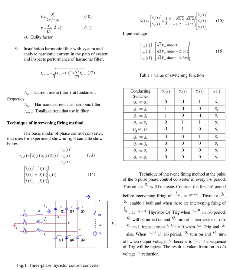
The basic modal of phase control converter, that uses for experiment show in fig.3 can able show below. ( ) ( ) ( ) ( ) ( ) ( ) ( ) an d a b c bn cn v t v t S t S t S t v t v t ⎡ ⎤ ⎢ ⎥ = ⎡⎣ ⎤ ⎢⎦ ⎥ ⎢ ⎥ ⎣ ⎦ (13) ( ) ( ) ( ) ( ) ( ) ( ) ( ) a a b b d c c i t S t i t S t i t i t S t ⎡ ⎤ ⎡ ⎤ ⎢ ⎥ ⎢ ⎥ = ⎢ ⎥ ⎢ ⎥ ⎢ ⎥ ⎢ ⎥ ⎣ ⎦ ⎣ ⎦ (14)
Fig.1 Three-phase thyristor control converter EquationSa( )t ,S tb( ) and S tc( ) are switching function vector formula S( )t of switching function can find like this ( ) ( )( ) ( ) ( ) ( ) 0 3 / 2 3 / 2 2 3 1 1/ 2 1/ 2 a x b y c S t S t S t S t S t S t ⎡ ⎤ ⎡ ⎤ ⎡ − ⎤ ⎢ ⎥ =⎢ ⎥= ⎢ − − ⎥ ⎢ ⎥ ⎢ ⎥ ⎣ ⎦ ⎢ ⎥ ⎣ ⎦ ⎣ ⎦ (15) Input voltage ( ) ( ) ( ) 2 sin( ) 2 sin( 2 / 3 ) 2 sin( 4 / 3 ) an an bn an cn an V t v t v t V t v t V t ω ω π ω π ⎡ ⎤ ⎡ ⎤ ⎢ ⎥ ⎢ ⎥ ⎢ ⎥ = − ⎢ ⎥ ⎢ ⎥ ⎢ ⎥ ⎢ − ⎥ ⎣ ⎦ ⎣ ⎦ (16)
Table 1 value of switching function
Conducting Switches ( ) a S t Sb( )t S tc( ) S( )t 5 Q และQ0 0 -1 1 S1 1 Q และQ6 1 -1 0 S2 1 Q และQ2 1 0 -1 S3 3 Q และQ2 0 1 1 S4 3 Q และQ4 -1 1 0 S5 5 Q และQ4 -1 0 1 S6 1 Q และQ4 0 0 0 S0 3 Q และQ6 0 0 0 S0 5 Q และQ2 0 0 0 S0
Technique of intervene fining method at the pulse of the 6 pulse phase control converter in every 1/6 period. This article S0 will be create. Consider the first 1/6 period
before intervening firing of
i
G1, at ωt=0. Thyristor Q3, 4Q
enable a both and when there are intervening firing of
1 G
i
, at ωt=0 Thyristor Q1 Trig when vab〉0 in 1/6 period. 1
Q
will be turned on and Q3 turn off then vector of o/p. d
v
and input current i i ia, ,b c= 0 when iG5 Trig and Q5
also. When vca〉0 in 1/6 period, Q5 turn on and Q1 turn
off when output voltage, vd become to vca. The sequence of Trig will be repeat. The result is value distortion in o/p voltage vd reduction.
ICCAS2005 June02-05, 2005 KINTEX(Korea International Exhibition Center),Gyeonggi-Do, Korea
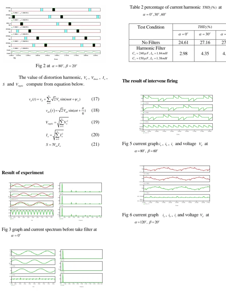
Fig 2 at α=80 ,ο β=20ο
The value of distortion harmonic, Vd, Vdmax, Ia,
S and Vripple compute from equation below.
1 ( ) 2 sin( ) d d n n n v t v V n tω ψ ∞ = = +
∑
+ (17) ( ) 2 sin( ) 6 ab ab v t = V ωt+π (18) 2 1 ripple n n V V ∞ = =∑
(19) 2 1 a n n I I ∞ = =∑
(20) 3an a S= V I (21) Result of experiment Time 140ms 145ms 150ms 155ms 160ms 165ms 170ms 175ms 180ms 136ms V(0,7) 200V 225V 250V I(VSc)V(1,5) -400 0 400 I(VSb)V(3,5) -400 0 400 SEL>> I(VSa)V(1,3) -400 0 400 Frequency 0Hz 100Hz 200Hz 300Hz 400Hz 500Hz 600Hz 700Hz 800Hz900Hz I(VSc) 0A 50A 100A SEL>> I(VSb) 0A 50A 100A I(VSa) 0A 50A 100AFig 3 graph and current spectrum before take filter at α =0o Time 140ms 145ms 150ms 155ms 160ms 165ms 170ms 175ms 180ms 136ms V(0,7) -400V 0V 400V I(VSc) -40A 0A 40A I(VSb) -40A 0A 40A SEL>> I(VSa) -40A -20A 0A 20A 40A Frequency 0Hz 0.1KHz0.2KHz 0.3KHz0.4KHz0.5KHz0.6KHz0.7KHz 0.8KHz0.9KHz 1.0KHz I(VSc) 0A 10A 20A I(VSb) 0A 10A 20A SEL>> I(VSa) 0A 10A 20A
Fig 4 graph and current spectrum behind take filter at 5th, 7th
and line reactor at α =0ο
Table 2 percentage of current harmonic THDi(%) at 0 , 30 , 60ο ο ο
α =
The result of intervene firing Time 140ms 145ms 150ms 155ms 160ms 165ms 170ms 175ms 180ms 136ms V(0,7) 88mV 90mV 92mV SEL>> I(VSc) -10A 0A 10A I(VSb) -10A 0A 10A I(VSa) -10A 0A 10A
Fig 5 current graphia, ib, ic and voltage Vd at 80 ,ο 60ο α= β= Time 120ms 125ms 130ms 135ms 140ms 145ms 150ms 155ms 160ms 165ms170ms V(0,7) 89.750mV 89.625mV SEL>> I(VSc) -400mA 0A 400mA I(VSb) -400mA 0A 400mA I(VSa) -400mA 0A 400mA
Fig 6 current graph ia, ib, icand voltage Vd at 120 ,ο 20ο α= β= (%) i THD Test Condition 0ο α = α =30ο α =60ο No Filters 24.61 27.16 27.36 Harmonic Filter 5 5 7 7 240 , 1.84 150 , 1.38 C F L mH C F L mH µ µ = = = = 2.98 4.35 4.65 784
ICCAS2005 June02-05, 2005 KINTEX(Korea International Exhibition Center),Gyeonggi-Do, Korea
Table 3 value of current harmonic THDi(%) at 30ο 120 ,ο 0ο 60ο
α= − β= − comparison with normally trig
From fig. 3 and 4 α =0 ,30 , 60ο ο ο harmonic filter passive can able reduction distortion harmonic but we consider THD(%) when the value of Trig’s angle increase to much then input current and output voltage reduction the quality of filter reduction also.
Summarize
Reduction distortion harmonic from 6-pulse phase control converter show by to change space vector then can able make zero vector of output voltage and input current become to zero via every 1/6 period when comparison with passive harmonic filter
Reference
[1] N.Mohan, T.M. Undeland, and W. P. Robbins, Poer Electronics : Converter, Application, and Design-2nd Edition, John Wiley & Sons, Inc., 1995, pp. 138-153
[2] J. Lazar “Park-vector Theory of Line-commutated Three-Phase Bridge Converters” Serial editior Volume 1,Omikk Publisher Budapest,1987, pp. 14-66
[3] I. G. Park and J. T. Yoon, “Charecterizing the double Firing Method For three-phase thyristor phase controlled converter,” in Proc. IECON 96 , 1996, pp. 689-694 Double Firing Firing α β (%) i THD α THDi(%) 30 0 27.39 30 27.16 60 0 27.82 60 27.36 60 30 27.32 60 27.36 80 60 12.35 80 28.81 12 0 30 10.83 120 32.03 12 0 60 10.22 120 32.03 785