대변형 효과를 고려한 원주방향 관통균열 엘보우의 닫힘굽힘 한계하중에 미치는 내압 영향 평가
홍석표* · 김윤재†
Effect of Internal Pressure on Plastic Limit Loads for Elbows with Circumferential Through-wall Crack under Closing Bending Incorporating Large Geometry Change
Effects
Seok-Pyo Hong, Yun-Jae Kim
Key Words : Finite element limit analysis(유한요소한계해석), Circumferential through-wall crack(원주 방향관통균열), Pipe bends(곡관), Large geometry change effects(대변형효과), Plastic limit loads(소성한계하중)
Abstract
Based on three-dimensional (3-D) FE limit analyses, this paper estimates effect of internal pressure on plastic limit loads for elbows with circumferential through-wall crack under in-plane bending incorporating large geometry change effects. Circumferential through-wall crack in extrados is considered. The FE limit analyses using the large geometry change option provide plastic collapse loads (using the twice-elastic-slope method). For the bending mode, closing bending is considered. Other relevant variables affecting plastic limit loads are systematically varied, related to pipe bend geometry (the mean radius, thickness and bend curvature) and defect geometry (the length of circumferential through-wall crack).
기호설명
Mo 균열이 없는 곡관의 한계/TES 소성굽힘 하중
ML 균열이 존재하는 곡관의 한계/TES 소성 굽힘하중
Papply 곡관의 적용압력
σο 완전 탄-소성재료의 한계응력 λ 곡관 특성 변수(Bend characteristic)
TES 2 배 탄성구배법(Twice-elastic-slope)
1. 서 론
가스산업계와 원자력발전소의 구조 신뢰성 평가 에 있어 곡관(Pipe bend)의 최대 하중 지지능력을 산출하기 위한 지표인 소성 한계 하중(Plastic limit loads)은 매우 중요한 문제로 주요 관심대상이 되
어왔다.(1-6) 특히 내압과 모멘트를 동시에 받는 복
합하중 하에서의 결함이 없는 엘보우에 대한 내압 영향 평가(7)는 발표되었으나, 균열이 존재하는 엘 보우에 대한 연구는 아직까지 명확히 알려져 있지 않다. 본 논문에서는 다양한 균열이 존재하는 엘 보우 형상에 대해 3 차원 유한요소 해석을 실시하 여, 기존의 식을 기반으로 대변형 효과를 고려한 원주방향 관통균열 엘보우의 닫힘굽힘 한계하중에 미치는 내압 영향 평가에 대한 근사식을 제시하였 다.
† 고려대학교 기계공학과
E-mail : [email protected]
TEL : (02)3290-3372 FAX : (02)926-9290
2. 유한요소 한계해석
2.1 형상과 유한요소망
(a) (b)
(c)
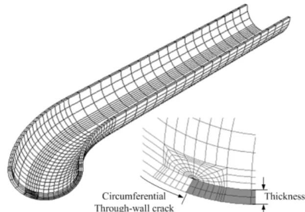
Fig. 1 Schematic of elbow ; (a) 90˚pipe bend (b) circumferential through-wall crack, and (c) pipe bends with attached straight pipes
Fig.1 은 본 연구에서 사용된 원주방향 관통균열 엘보우의 형상을 나타낸 것이다. 곡관에 직관을 접합시킨 형상은 굽힘 하중이 작용하는 곡관의 해 석에서 경계조건 적용에 대한 어려움을 없애주기 때문에 보편적으로 사용한다. 직관의 길이는 곡관 의 외경에 5 배(L=5Do)로 설정하였다.(8)
곡관의 형상 변수는 다음과 같다. 평균반지름과 두께는 r 과 t, 굽힘 반지름은 R 이고, 곡관과 연결 된 직관의 길이는 L 이며, 곡관 특성 변수(bend characteristic)는 다음과 같이 정의된다.
( ) ( )
r t r R rRt == 2
λ (1)
위의 무차원 변수는 R/r 과 r/t 가 독립적으로 변 함에 따라 λ 는 0.1 부터 0.5 까지 변화하며, 이에 따라 곡관 형상의 효과가 정량화된다.
균열은 곡관 내부의 외호(extrados)에 존재하며 곡관에 존재하는 균열의 형상에 대한 무차원 변수 는 θ/π 이다.
유한요소 해석시간을 줄이기 위해 1/4 대칭조건 의 3 차원 모델을 사용하였다. Fig. 2 는 본 연구에 사용된 유한요소망이다. 비압축성에 수반되는 문 제점을 해결하기 위해, ABAQUS 의 reduced integration elements (C3D20R)를 사용하였다.
Fig. 2 A typical finite element mesh, employed in the present work
2028 개의 요소와 11528 개의 절점을 사용하였고, 두께 방향으로 2 개의 요소를 사용하였다.
2.2 유한요소해석
유한요소해석은 범용 유한요소해석 프로그램인 ABAQUS Ver. 6.4.를 이용하여 수행하였다. 재료는 소성 한계 하중의 계산을 위하여 탄성-완전소성 (elastic perfectly plastic)재료로 가정하였다. 하중조 건은 내압과 평면 굽힘하중이 하중 조건으로 주어 졌다. 내압은 유한요소 모델의 내면에 전체적으로 분포력으로 가하였다. 곡관 끝단의 닫힘을 고려하 여, 내압에 의한 축방향 응력을 곡관 끝단에 가하 였다. 탄성-완전 소성 유한요소 해석 시 수반되는 수렴문제를 해결하기 위해서, ABAQUS 의 RIKS 옵션을 사용하였다. 굽힘하중인 경우에 직관의 끝 단의 절점을 ABAQUS 의 MPC(multi-point constraint)를 이용하여 구속시키고 충분한 회전을 통해 굽힘하중을 가하였다. 내압과 굽힘하중이 가 해지는 경우, 대변형 효과를 고려한 해석을 수행 하였다.
3. 결과
3.1 결함이 없는 곡관의 닫힘굽힘 한계하중에 미치는 내압영향 평가
최근 Kim(7)은 결함이 없는 곡관의 닫힘굽힘 한 계하중에 미치는 내압 영향 평가식(2)을 제시한바 있다.
( )
2 3
0 1
apply apply apply
o
o o o o
P P P
M r r r
M P α t β t γ t
σ σ σ
= + + +
=
(2)
( )
4 2 nc
o o c c
M = σ r t A⋅ λ+k
0.017 0.911
0.127
0.800 ; 1.460 ;
0.423
c c
c
r r
A k
t t
n r
t
− −
= =
=
3 2
135 202.5 101.25 14.575 0.3 0.5
1.22 0.1 0.3
for for
λ λ λ λ
α λ
− + − ≤ ≤
= ≤ ≤
105 2 105 23.75 0.3 0.5
1.70 0.1 0.3
for for
λ λ λ
β λ
− + ≤ ≤
= ≤ ≤
for r/t=20;
75 2 75 18.83 0.3 0.5
3.08 0.1 0.3
for for
λ λ λ
γ λ
− + − ≤ ≤
= − ≤ ≤
0.18 0.07 r α= − + t
3 2
0.0005 r 0.0075 r 0.0375 r 0.05
t t t
β= − + −
for 5≤ r/t <20.
2
0.011 r 0.110 r 0.880
t t
γ= − + −
3.2 원주방향 관통균열이 존재하는 곡관의 닫힘 굽힘 한계모멘트
최근 Kim(9)은 대변형 효과를 고려한 원주방향 관통균열이 존재하는 곡관의 닫힘굽힘 한계하중식 (3)을 제안하였다.
( )( )
=
π σ θ
λ r t f
ML 1.075 23 4 2 o (3)
≅
≤
≤
−
−
≤
≤
=
) 42 . 0 36( 15 8 for 1 0806 . 2 7236 . 0 1194 . 1
8 0 1 for 0
. 1
2 π θ π
θ π θ
π θ π
f θ
for r/t=5;
≅
≤
≤
−
+
≤
≤
=
) 42 . 0 36( 15 6 for 1 68 . 4 0152 . 1 9655 . 0
6 0 1 for 0
. 1
2
π θ π
θ π θ
π θ π
f θ for r/t=10;
≅
≤
≤
−
+
≤
≤
=
) 42 . 0 36 ( 15 4 for 1 92 . 7 42 . 3 64 . 0
4 0 1 for 0
. 1
2
π π θ π
θ π θ
π θ π
f θ
for r/t=20.
3.3 원주방향 관통균열이 존재하는 곡관의 닫힘 굽힘 하중에 미치는 내압영향 평가
본 연구에서는 식(2), (3)을 바탕으로 하여 외 호(extrados)에 원주방향 관통균열이 존재하는 곡관의 닫힘굽힘 한계하중에 미치는 내압 영향 평가식(4)을 형상 변수를 적용하여 다음과 같이 제안한다.
( )
2 3
1 ' ' '
0
apply apply apply
L
L o o o
P P P
M r r r
M P α t β t γ t
σ σ σ
= + + +
=
(4)
2 2 2
' 0.45 0.13 r 0.0143 r 10.17 0.45 r 0.03 r
t t t t
θ θ
α α
π π
= + + + + − − −
2
3 4
56.24 1.286 243.57 19.14
12.5 20 ' 475.14 81.11 354.92 85.337
4.205 1.0455
r r
t t r
for t
r r
t t
r fo
t
θ θ
β π π
θ θ
β π π
β θ
π
+ − + − − < ≤
= + + + − −
+ − 5 r 12.5
r ≤ ≤t 2
3 4
26.88 1.5 11.38 42.55
12.5 20 267.11 160.54 548.12 185.1
'
7.444 1.3194 25.
r r
t t r
for t
r r
t t
r t
θ θ
γ π π
θ θ
π π
γ γ θ
π
+ − − + + < ≤
+ − + − +
=
+ − + +
2
3
19 4.07
5 12.5 50.26 10.052
r
t r
for t r
t
θ π θ
π
−
≤ ≤
+ − +
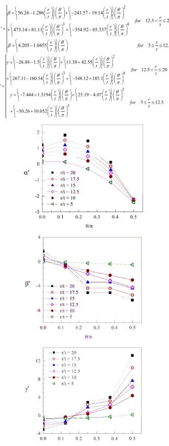
Fig. 3 Comparisons of three correction factors related to pipe bend geometry (the mean radius, thickness and bend curvature) and defect geometry (the length of circumferential through- wall crack).
(a)
(b)
(c)
(d)
(e)
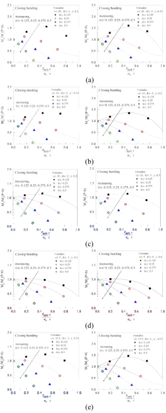
Fig. 4 Comparison of proposed solution with FE results under combined pressure and closing bending:
(a) r/t=20, (b) r/t=15, (c) r/t=10, (d) r/t=5, (e) r/t=12.5 and 17.5
Fig. 3 은 본 논문에서 제안한 외호(extrados)에 원주방향 관통균열이 존재하는 곡관의 닫힘굽힘 한계하중에 미치는 내압 영향 평가식에서 각항의
있는지를 보여주고 있다.
α '는 결과의 궤적에서 초기기울기(initial slope) 를 결정 짓는데 있어 가장 지배적인 보정계수이며, 모든 r/t 에서 같은 경향성을 갖는 것으로 확인되 었다.
β '는 최고값(peak value)을 결정 짓는데 있어 가장 지배적인 보정계수이며, 5≤r t/ ≤12.5의 범 위에서는 결과의 궤적이 1 차 함수의 경향성을 보 였고, 12.5<r t/ ≤20의 범위에서는 4 차 함수의 경향성을 보였다.
γ '는 폭(width)을 결정 짓는데 있어 가장 지배 적인 보수이며, 5≤r t/ ≤12.5의 범위에서는 결과 의 궤적이 3 차 함수의 경향성을 보였고, 12.5<r t/ ≤20의 범위에서는 4 차 함수의 경향성 을 보였다.
따라서 본 논문에서는 이러한 경향성을 토대로 하여 외호(extrados)에 원주방향 관통균열이 존재 하는 곡관의 닫힘굽힘 한계하중에 미치는 내압 영 향 평가식(4)을 제안한다.
Fig. 4 는 외호(extrados)에 원주방향 관통균열을 가진 곡관에 대하여 다양한 R/r, r/t, θ/π 를 고려했 을 경우 닫힘굽힘 한계하중에 미치는 내압 영향 을 보여주고 있으며, 제안식과 유한요소해석 결과 가 잘 일치되는 것을 볼 수 있다.
4. 결 론
본 논문에서는 3 차원 유한요소해석을 통해 굽힘 하중과 내압하중이 결합된 하중상태하에서 원주방 향 관통균열 곡관의 소성한계하중을 계산하고 해 석결과를 이용하여 곡관의 닫힘굽힘 한계하중에 미치는 내압 영향 평가식을 제안하였다. 본 논문 에서 제안한 내압 영향 평가식은 유한요소 해석에 기초한 식이므로 비교적 정확한 식이라 할 수 있 으며, 곡관의 소성붕괴 및 여러가지 파괴역학 매 개변수의 예측에 유용하게 적용할 수 있다.
참고문헌
(1) Spence J, Findlay GE., 1973, “Limit load for pipe bends under in-plane bending,” Proc. 2nd Int. Conf.
On Pressure Vessel Technology, San Antonio, 1-28:
393-399.
(2) Calladine CR., 1974, “Limit analysis of curved tubes,” Journal of Mechanical Engineering Science, vol. 16, pp. 85-87.
(3) Goodall IW., 1978, “Lower bound limit analysis of curved tubes loaded by combined internal pressure and in-plane bending moment,” CEGB report RD/B/N4360 Central Electricity Generating Board.
(4) Miller AG., 1988 “Review of limit loads of
Pressure Vessels and Piping, Vol. 32, pp. 191–327.
(5) Robertson A, Li H, Mackenzie D., 2005, “Plastic collapse of pipe bends under combined internal pressure and in-plane bending,” International Journal of Pressure Vessels and Piping, Vol. 82, pp. 407-16.
(6) Chattopadhyay J, Natahani DK, Dutta BK, Kushwaha HS., 2000, “Closed-form collapse moment equations of elbows under internal pressure and in- plane bending moment,” Journal of Pressure Vessel Technology, Vol.122, pp. 431-6.
(7) Kim Y-J,Oh C-S., “Closed-form plastic collapse loads of pipe bends under combined pressure and in- plane bending,” Engineering Fracture Mechanics, Vol.
73,pp.1437-1454, 2006.
(8) Kim, YJ. and Oh, CS., “Effect of attached straight pipes on finite element limit analysis of pipe bends”, International Journal of Pressure Vessels and Piping (submitted for publication).
(9) Kim, Y-J., Kim, Y-I. and Song, T-K., 2006, “Finite element plastic loads for circumferential cracked pipe bends under in-plane bending”, Engineering Fracture Mechanics, Vol. 74, pp. 643-668.