Abstract
The hybrid simulation test method is a versatile technique for evaluating the seismic performance of structures by seamlessly integrating both physical and numerical simulations of substructures into a single test mode. In this paper, a software framework that integrates computational and experimental simulation has been developed to simulate and test a bridge structural system under earthquake loading. Using hybrid simulation, the seismic response of complex bridge structural systems partitioned into multiple large-scale experimental and computational substructures at networked distributed experimental and computational facilities can be evaluated. In this paper, the examples of application are presented in terms of a bridge model with soil-foundation-structure interaction.
요 지
하이브리드 시뮬레이션 실험방법은 단일실험모드하의 물리적 또는 수치해석적 시뮬레이션에 의하여 지진 발생시 구조물을 평가하는 다양한 기술 중에 하나이다. 본 논문에서는 지진하중하의 교량구조 시스템의 해석 과 실험을 위해서 계산과 실험 시뮬레이션을 통합한 소프트웨어체제를 개발하였다. 개발한 하이브리드시뮬레 이션 소프트웨어체제를 이용하여 대규모 네트워크로 분산된 실험 또는 전산장비에 참여하고 있는 교량구조시 스템에 대한 지진응답을 평가할 수 있었다. 본 논문에서는 적용 예를 통하여 지반 구조 상호작용을 고려한 교량의 시뮬레이션 해석방법을 제시하였다.
Keywords : Bridges, Hybrid simulation, Seismic response, Soil-foundation-structure interaction 핵심 용어 : 교량, 하이브리드 시뮬레이션, 지진응답, 지반구조상호작용
지반 구조 상호작용을 고려한 교량 시뮬레이션 시스템
Bridge Simulation System with Soil-Foundation-Structure Interaction
김 익 환*
한 봉 구
**
Kim, Ik-Hwan Han, Bong-Koo
1)
* 서울산업대학교 건설공학부 석사과정
** 정회원, 서울산업대학교 건설공학부 교수, 공학박사
E-mail : [email protected] 02-970-6577
•본 논문에 대한 토의를 2008년 8월 31일까지 학회로 보내 주시면 2008년 11월호에 토론결과를 게재하겠습니다.
1. Introduction
Hybrid simulation, including real-time dynamic testing of substructures, provides an efficient method for assessment of dynamic and rate- dependent behavior of structural systems subjected to earthquake excitation. Depending on the objectives of the experiment, a real time hybrid test may have several advantages over a dynamic shaking table test in terms of cost, scale, geometry, and required physical mass of structural model. Hybrid simulation is now widely recognized as a reliable alternative to shaking table tests that can provide a better understanding of critical substructure behavior at large scales.
Hybrid simulation is a versatile technique for evaluating the seismic performance of structures by seamlessly integrating both physical and numerical simulations of sub- structures into a single test model. Testing of large-scale structures is the most reliable method for assessment of seismic performance of structures. However, physical testing of such structures including soil-foundation- structure interaction remains extremely space- and equipment-intensive as well as costly.
A scalable framework with a fault-tolerant distributed controller is presented to support the implementation of advanced hybrid testing methods with distributed substructures. The control strategy is based on a multithreaded simulation coordinator for parallel communication with remote sites and an event-driven controller at each remote experimental site to implement continuous loading.
Real-time hybrid simulation is a natural evolution of pseudo-dynamic test methods
developed over the past decades (Mahin SA, Shing PSB 1985). In a real-time hybrid simulation, experimental substructures are loaded at realistic rates and the dynamic inertial forces are typically modeled numerically. The importance of experimental errors, especially systematic errors such as time delay, was recognized early on in the extension of pseudo-dynamic testing to fast and real-time application of loads on experimental sub- structures (Nakashima M, Kato H, Takaoka E 1992).
As with any feedback system, response delay of servo-hydraulic actuators and measurement errors can erroneously alter the results of hybrid simulations. Most importantly, the inherent delay of servo-hydraulic actuators can produce a negative damping effect, adding energy into a hybrid simulation. Darby et al.
demonstrated that actuator time delay can vary during a hybrid simulation, particularly as the stiffness of the experimental specimen changes. Consequently, a significant part of the literature on fast hybrid simulation is dedicated to the development of actuator delay compensation and signal correction procedures. (Horiuchi T et al. 1999)
Hybrid simulation combines numerical and experimental methods to evaluate the seismic performance of structures. The principles of the hybrid simulation test method are rooted in the pseudo-dynamic testing method developed over the past 30 years.
In a hybrid simulation, the dynamic equation
of motion is solved for the hybrid numerical and
experimental model. Typically, the experimental
substructures are portions of the structure
that are difficult to model numerically, thus,
their response is measured in a laboratory.
Numerical substructures represent structural components with predictable behavior: they are modeled using a computer. Comparative experiments have shown that the hybrid simulation test method in which inertial effects are simulated numerically can provide results comparable to the shaking table test method when propagation of experimental errors is successfully mitigated (Takanashi and Nakashima 1987; Magonette and Negro 1998).
Hybrid simulation procedures based on the pseudo-dynamic approach have advanced considerably since the method was first developed. Early tests utilized a ramp-and- hold loading procedure on the experimental elements. Continuous testing at slow (Magonette 2001) and fast rates (Nakashima 2001) have improved hybrid simulations by mitigating strain-rate related errors during displacement hold portions of the tests (Stojadinovic et al.
2006)
The capabilities of hybrid simulation have been further extended by geographically distribute experimental substructures within a network of laboratories linked through numerical simulations using the internet. In this approach, the master simulation solving the equation of motion of the entire structure can be carried out on supercomputers if necessary and networked to one or more experimental facilities with remote substructures. The infrastructure of the George E. Brown Jr. Network for Earthquake Engineering Simulation (NEES) provides the experimental facilities, the numerical modeling tools, and the network interface to enable simultaneous testing of multiple large- scale experimental and numerical substructures using distributed hybrid simulation. This
approach allows for the evaluation of complex structural systems through the partitioning of the model into multiple experimental and numerical substructures. The experimental substructures can be evaluated at large or full scale under realistic simulated seismic loading while at the same time capturing the interaction of the test specimens with the complete structural system.
As part of the George E. Brown Jr. Network for Earthquake Engineering Simulation (NEES), the Multi-axial full scale substructure testing and simulation (MUST-SIM) facility is currently under construction at the University of Illinois at Urbana-Champaign. (Elnashai B.F et al.
2004) A unique feature of the MUST-SIM facility is the integrated computational and experimental simulation software framework being developed in conjunction with the physical facility. The integrated computational and experimental simulation framework allows the seamless integration of multiple physical and numerical simulations of structural and geotechnical components within a unified simulation of a full-scale system such as a bridge with soil foundation structure Interaction effects.
The distributed testing methods can be
integrated into these various simulation
platforms to minimize experimental errors and
achieve reliable hybrid simulations of complex
structural systems. The objectives of the
distributed control strategy presented here
are: To provide a scalable framework for
multiple substructure testing at distributed
sites; Improve the reliability of the test
results by minimizing strain rate and force
relaxation errors in the remote experimental
substructures; and increase the speed of testing
as allowed by network communication time.
The control strategy is based on a multi- threaded simulation coordinator combined with an event-driven controller at the remote experimental sites. The multithreaded coordinator is applied to simultaneously load multiple remote substructures at different sites. The event-driven remote site controller allows for the implementation of continuous hybrid simulation algorithms on distributed models where computation, network communication, and other tasks may have random completion times. The advantage of this approach is that the hold phase in conventional ramp-and hold pseudo-dynamic testing, during which force relaxation has been observed, is minimized if not eliminated. These combined features also allow for faster rates of testing.
The distributed controller was implemented into NEESgrid, the cyber infrastructure linking the NEES equipment sites through and experiment-based deployment activity of the NEES system integration involving the University of California at Berkeley, University at Buffalo, University of Colorado at Boulder, the University of Illinois at Urbana-Champaign, and Lehigh University. This combined effort known as fast multisite on-line simulation test (Fast MOST), was targeted at introducing features into NEESgrid that allow for faster rates of testing and improved reliability of the simulation results. Building on the original MOST (Spencer et al. 2004), distributed control strategies were implemented into the NEES tele-control protocol (NTCP) (Pearlman et al.
2003) in order to increase the speed of testing and allow for the implementation of continuous algorithms.
2. Hybrid Simulation
In a hybrid simulation, the structure model is composed of physical (experimental) and numerical substructures. Typically, numerical simulations consist of parts of the structure that can be adequately modeled and experimental substructures are used for capturing the behavior of more complicated components. The boundary conditions between the experimental and numerical substructures are enforced through proper communication of interface forces and displacements and the use of servo-hydraulic actuators.
The equation of motion governing the response of the hybrid numerical and experimental models is given by
(1)
where M and C are mass and damping matrices of the experimental substructure, r and
are numerical and experimental restoring force vectors, and f is the external force vector. Equation(1) is solved using a time- stepping numerical integration procedure similar to dynamic finite element analysis. Here, it is assumed that the measured force signal has a time delay, resulting from delays in the physical test setup. It is important to note that in a fast simulation,
may contain velocity- dependent and inertial forces, which should be subtracted from the numerical mass and damping matrices. A similar approach for splitting the numerical and experimental mass has been suggested for effective force testing.
(Chen C, Ricles J.M 2006)
This study focuses primarily on displacement-
controlled pseudo-dynamic hybrid simulations,
in which displacements computed using the numerical model are applied to the physical specimen, and the resisting forces are measured and feedback into the numerical model. The nature of physical experiments normally results in small but influential differences between the desired and achieved displacement histories.
These small differences maybe tolerable in an ordinary open-loop experiment such as quasi- static testing, since the displacement or force history imposed by the actuators is previously known, and will not be altered by errors.
Furthermore, offline tools for processing experimental data generally make it possible to remove the majority of these errors. In contrast, experimental errors in feedback systems, such as hybrid simulation, may accumulate during the simulation and alter the load path of the experimental substructures.
Thus, compensation of signals transmitted between numerical and experimental substructures is critical to the stability and accuracy of the simulation. For this reason, two correction and compensation blocks have been included: one acting on the actuator command signals and the other on the measurements fed back to the numerical simulation. These correction modules can be used individually or simulta- neously. In the latter, force correction procedures allow for additional corrections of actuator tracking errors that exist even after careful compensation of the command displacement signal.
3. Simulation Framework for Pseudo- dynamic Testing
In its simplest application, the integrated computational and experimental simulation
(ICES) framework is capable of performing pseudo-dynamic (PSD) testing of a selected structure component. However, as the framework is capable of virtually representing an entire structural system, it is used to pseudo- dynamically test more than one component at the MUST-SIM facility or a combination of several NEES facilities. Currently, the integrated computational and experimental simulation controller incorporates two numerical time integration algorithms; α-Operator Splitting method and new Predictor-Corrector method.
A schematic of the integrated computational and experimental simulation software framework is applied to sub-structured pseudo-dynamic test considering soil-foundation-structure interaction problems. The integrated computational and experimental simulation framework uses communication protocols that are compatible with the NEES Point-of-Presence (NEESpop) system to perform the distributed numerical and experimental simulation. MUST-SIM facility will be run as a NEESgrid infrastructure system which includes NEESpop, DAQ, NSDS and CHEF. The NEESgrid system is under continuous development as part of NEES System Integration project.
The purpose of Fast-MOST was to combine the state of the art in hybrid testing with the state of the art in secure network communi- cations. Use of the NTCP network protocol in hybrid simulation was first demonstrated in the July 2003 MOST (Spencer et al. 2004).
In this previous application, the emphasis of
NTCP was on security and safe control of
remote experimental equipment. In order to
increase the rates of testing for Fast-MOST,
three key enhancements were incorporated
into NTCP: (1) modification of NTCP to
minimize network transactions in each simulation step; (2) implementation of a Java- based multithreaded simulation coordinator to carry out transactions in parallel with multiple remote sites; and (3) implementation of an event-driven controller at remote experimental sites that generate a continuous load history for the experimental substructures.
It should be noted that in modifying the original NTCP, control and security features had to be relaxed. Thus a balance was sought between the most essential security and control features that would provide the fastest rates of testing. Detailed implementation of performance enhancements is discussed in the sections that follow.
The original NTCP protocol used in MOST was designed for security and reliability (Pearlman et al. 2003). Design goals were to provide a mechanism for conducting multisite distributed testing using a standard, well defined protocol. The resulting protocol provided effective safety control features to pause and restart the simulation in case problems were encountered, but was less efficient in terms of network utilization and the rate of testing.
Typical integration step durations during the MOST experiment were on the order of 13s with the majority of this time dedicated to network communication and overhead in the software interface.
For each integration step in the MOST simulation, at least two round-trip network communications were required for each remote site. First, the simulation coordinator received the target displacements from the master simulation. Next, the simulation coordinator executed a propose request with the target encapsulated in a control point parameter for
each remote site. Each remote site replied back to the simulation coordinator indicating whether it accepted its proposal. If the proposed request was accepted for all sites, the simulation coordinator sent an execute request to each site. Upon receiving an execute request, the experimental sites commanded the actuator to the target displacement and returned the measured displacement and forces to the simulation coordinator. Finally, the simulation coordinator sent the feedback to the master simulation and repeated the process in the next step.
4. Bridge Simulation with Soil Foundation Structure Interaction
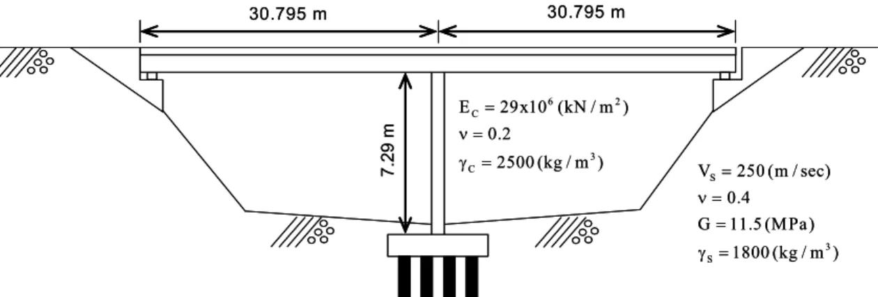
The example is presented to demonstrate the versatility of the integrated computational and experimental simulation framework and the performance of the pseudo-dynamic time integration algorithms. The example is soil- foundation-structure interaction analysis of a bridge. All the experiments are virtual experiments whereby the experimental modules are represented by an equivalent static numerical analysis. Distributed simulation (physical and analytical) of a steel frame structure is described in a paper by Spencer et al. and is illustrated in Figure 1. One of the El Centro earthquake records is used as the input ground motion.
The purpose of this simulation is to test the capabilities of the integrated computational and experimental simulation controller for soil-foundation-structure interaction problems.
A hypothetical two-span bridge with approach
embankments is developed for virtual pseudo-
dynamic simulation. Owing to the generality of
7.2 9 m
30.795 m 30.795 m
S
3 S
V 250 (m / sec) 0.4
G 11.5 (MPa) 1800 (kg / m )
= ν =
= γ =
6 2
C
3 C
E 29x10 (kN / m ) 0.2
2500 (kg / m )
= ν =
7.2 9 m γ =
30.795 m 30.795 m
S
3 S
V 250 (m / sec) 0.4
G 11.5 (MPa) 1800 (kg / m )
= ν =
= γ =
6 2
C
3 C
E 29x10 (kN / m ) 0.2
2500 (kg / m )
= ν = γ =
Fig. 1 Bridge for soil-foundation-interaction problem
Abutment
(kN/m) Pier (kN/m) Longitudinal 2.20 x 10⁵ 2.04 x 10⁵
Transversal 1.87 x 10⁵ 1.94 x 10⁵
Vertical 6.66 x 10⁵ 3.50 x 10⁵ Rocking around
longitudinal 2.20 x 10⁵ 1.44 x 10⁶ Rocking around
transversal 7.38 x 10⁵ 6.69 x 10⁵ Table 1 Stiffness of soil spring
the integrated computational and experimental simulation controller, the bridge can be represented with multi-components of either computational or experimental modules. Figure 1 shows the schematic of this bridge with its approach embankments. Both abutments are assumed to consist of reinforced concrete pier wall connected by a curtain wall. The deck and abutment mass are assumed to be rigidly connected. As show in Fig. 1, piles and soil system is replaced with frequency- independent soil springs. Inertia forces due to abutments and foundation of pier are considered through mass element. For an input ground motion, El Centro ground motion is imposed to the transverse direction. Employing sub-structuring technique, pier foundation/soil layer and deck and abutments system are represented by computational module and pier itself is represented by experimental module.
To evaluate the stiffness of soil springs under the pier foundations, three-dimensional finite element analysis has been conducted using beam and eight-node solid element in ABAQUS. Table 1 shows the spring stiffness computed and assumed in this example.
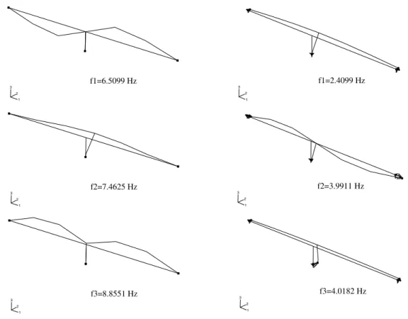
In the numerical model, damping effect is
considered by assuming modal damping ratio
5.0% in the first and the second mode. To
evaluate changes of dynamic characteristics
due to soil-foundation-structure interaction
effect, eigenvalue analysis is conducted on
this model. Fig. 2 shows comparison of its
first three natural frequencies between model
with no soil-foundation-structure interaction
effect and model with soil-foundation-structure
interaction effect. From this comparison, it
can be judged that the soil-foundation-structure
interaction effect should bring significant
change of dynamic characteristics and lead to
different responses under excitation such as
earthquake ground motion.
1 2
3 f1=6.5099 Hz
1 2
3 f1=2.4099 Hz
1 2
3 f2=7.4625 Hz
1 2
3 f2=3.9911 Hz
1 2 3
f3=8.8551 Hz
1 2
3 f3=4.0182 Hz
Fig. 2 Natural frequencies of model with no SFSI effect and with SFSI effect
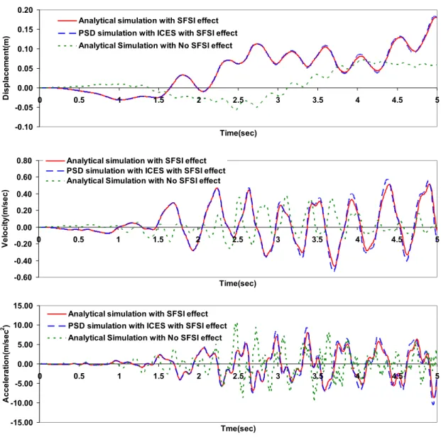
To test the capabilities of integrated computational and experimental simulation controller, virtual sub-structured pseudo-dynamic simulation considering soil-foundation-structure interaction effect has been conducted and compared with a single-model analytical simulation results computed by ABAQUS. Fig.
3 plots horizontal responses of displacement, velocity and acceleration at the interface point between pier and bridge deck. The influence of SSI follows the expected trends of elongated periods and increased displacement amplitude.
The integrated computational and experimental simulation distributed simulation is shown to be capable of replicating the results of the single-model analysis.
Assessment of the above demonstration examples confirms that the integrated computational and experimental simulation framework is applicable to the simulation of complex structural-geotechnical system in a sub- structured pseudo-dynamic testing environment.
In the future, the integrated computational and experimental simulation controller will also include many innovative features utilizing information from real experiments.
5. Conclusion
The hybrid simulation test method is a
versatile technique for evaluating the seismic
performance of structures by seamlessly
-0.60 -0.40 -0.20 0.00 0.20 0.40 0.60 0.80
0 0.5 1 1.5 2 2.5 3 3.5 4 4.5 5
Time(sec)
V e lo c ity (m/s e c )
Analytical simulation with SFSI effect PSD simulation with ICES with SFSI effect Analytical Simulation with No SFSI effect
-15.00 -10.00 -5.00 0.00 5.00 10.00 15.00
0 0.5 1 1.5 2 2.5 3 3.5 4 4.5 5
Tme(sec) A c c e le ra ti on( m /sec
2)
Analytical simulation with SFSI effect PSD simulation with ICES with SFSI effect Analytical Simulation with No SFSI effect
Fig. 3 Horizontal responses at the interface point between bridge deck and pier