Ce
0.8Sm
0.2O
2Sol-gel Modification on La
0.8Sr
0.2Mn
0.8Cu
0.2O
3Cathode for Intermediate Temperature Solid Oxide Fuel Cell
Seung Jin Lee, Choon-Hyoung Kang, Chang-Bock Chung and Jeong Woo Yun† School of Applied Chemical Engineering, Chonnam National University, Gwangju 500-757, Korea
(Received December 10, 2015: Corrected December 24, 2015: Accepted December 29, 2015)
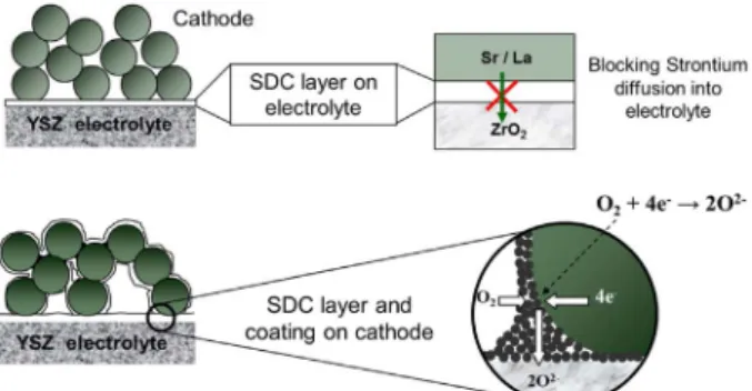
Abstract: To increase the performance of solid oxide fuel cell operating at intermediate temperature (600oC~800oC), Sm0.2Ce0.8O2 (SDC) thin layer was applied to the La0.8Sr0.2Mn0.8Cu0.2O3 (LSMCu) cathode by sol-gel coating method. The SDC was employed as a diffusion barrier layer on the yttria-stabilized zirconia(YSZ) to prevent the interlayer by-product formation of SrZrO3 or La2Zr2O7. The by-products were hardly formed at the electrolyte-cathode interlayer resulting to reduce the cathode polarization resistance. Moreover, SDC thin film was coated on the cathode pore wall surface to extend the triple phase boundary (TPB) area.
Keywords: Intermediate-temperature solid oxide fuel cell, Diffusion barrier layer Sm0.2Ce0.8O2, La0.8Sr0.2Mn0.8Cu0.2O3
1. Introduction
Solid oxide fuel cells (SOFCs) are energy conversion devices that produce electricity via the electrochemical reactions of fuel and oxidant gases across an ionic-conduc- tion ceramic. Due to its high efficiency and wide operating temperature range (800~1000oC), SOFCs have been con- sidered as one of the most promising power generation sys- tems such as power plant and electricity-heat cogeneration system. Operating such high temperature over 800oC, how- ever, creates technical limitations such as the gas leakage and interconnecting materials, and metal particle sintering of electrode in long-term operation.1,2) To overcome such problems the considerable research efforts have been attempted to reduce the operating temperature.3-9) Opera- tion at low temperature (below 700oC) decreases the cell performance caused by increasing polarization resistance of electrode as well as decreasing the ionic conductivity of electrolyte. The polarization of cathode might more affect to decrease the cell performance than that of anode at low temperature operation.10,11) La1-xSrxCo1-yFeyO3 (LSCF) has been considered as a promising alternative cathode mate- rial because LSCF exhibits a higher electronic and ionic conductivity than currently used LaxSr1-xMnO3 (LSM) at the low temperature.12,13) LSCF, however, would react with YSZ electrolyte to form the electronic and ionic resistant
products such as La2Zr2O7 and SrZrO3 at the interface between the cathode and electrolyte.14) Therefore, to mini- mize the unfavorable by-product formation, buffer layer between electrolyte and cathode is necessary for using the LSCF as a cathode.
Rare metal doped ceria including SDC (Sm1-xCexO2-δ), GDC (Gd1-xCexO2-δ) and YDC (Y1-xCexO2-δ) is well known as a catalytic material and also is a mixed ionic and elec- tronic conductor.15-18) Therefore, placing the continuous thin layer of doped ceria on the cathode pore wall surface can improve both electronic and ionic properties of the cathode leading electrochemically active for the entire cathode. As the results, additional triple phase boundary can be extended lending improvement of the cell perfor- mance by placing the doped ceria on the cathode pore wall surface. In addition, placing the doped ceria as a buffer layer between electrolyte and cathode can be one approach to prohibit formation of the unfavorable by-product.
In our previous study,19,20) we modified cathode by plac- ing SDC and GDC buffer layer between LSCF cathode and YSZ electrolyte. The interfacial reaction product such as SrZrO3 was hardly produced at the interlayer electrolyte and cathode by placing SDC buffer layer. In addition, the TPB area was increased by SDC and GDC coating on cath- ode pore wall surface, leading reduction of the cathode polarization resistance.
†Corresponding author E-mail: [email protected]
© 2015, The Korean Microelectronics and Packaging Society
This is an Open-Access article distributed under the terms of the Creative Commons Attribution Non-Commercial License(http://creativecommons.org/
licenses/by-nc/3.0) which permits unrestricted non-commercial use, distribution, and reproduction in any medium, provided the original work is properly cited.
In this study, LSMCu cathode was developed as an alter- native cathode for intermediate temperature SOFCs and it was modified by SDC as a buffer layer to prevent forma- tion of the unfavorable by-product. In addition, SDC was coated on cathode pore wall surface to improve the cathode performance by extending additional TPB area as illus- trated in Fig. 1.
2. Experimental
Strontium nitrate (Sr(NO3)3·H2O, Aldrich), Lanthanum nitrite hexahydrate(La(NO3)3·6H2O), Manganese(II) ace- tate tetrahydrate (Mn(CH3COO)2·4H2O), and Copper(II) nitrate pentahydrate(Cu(NO3)2·5H2O were synthesized to fabricate La1-xSrxMn1-yCuyO3 cathode by the Pechini method as shown in Fig. 2. The SDC sol was prepared from a com- mercial CeO2 colloidal dispersion (0.01~0.02 mm particles in H2O, Alfa Aesar). The commercial CeO2 sol was diluted with distilled water and Sm nitrate (Sm(NO3)3)6H2O, 99.9%, Aldrich) in distilled water was added to the dilute CeO2 sol while stirring the solution in order to make 20 mol% Sm doped Ceria ((CeO2)0.8(Sm2O3)0.2) sol. The syn-
thesized crystal structures were analyzed by an X-ray dif- fractometer (XRD, Rigaku, RINT-5200). The YSZ electrolyte was made by uniaxial pressurization (Carver press inc.) using a commercial 8mol% Y2O3-ZrO2 powder (TZ-8YS, Tosoh) and sintered to prepare an disk type cell at 1400oC for 10 hours. After polishing by SiC sandpaper (#1000) and washing by isopropyl alcohol in ultrasonic cleaner, it was fabricated 25 mm in diameter and 1mm in thickness YSZ disk. La0.8Sr0.2Mn0.8Cu0.2O3 (LSMCu) paste were prepared by mixing of the powder and additives including methylcellulose and water. The cathodes were coated on the surface of the YSZ electrolyte by tape cast- ing method, and sintered at 1000~1200oC for 2 hours. In order to decrease or inhibit interface reactions between the cathode and yttria-stabilized zirconia (YSZ) electrolyte for both cathode materials, 1~2 μm thickness Sm0.2Ce0.8O2 (SDC) buffer layer was formed on interface by dip-coating method. Moreover, after cathode sintering, the layer of SDC was deposited within pore wall of the microstructure control with the same procedure, followed by calcinations at 700oC for 2 hours. The microstructure and composition of the coating were analyzed by an elecro-probe microana- lyzer (FE-EPMA, JXA-8500F, JEOL Ltd. Japan). For anal- ysis of cell performance, Ni/YSZ anode supported fuel cells were prepared by SDC-modified LSMCu cathodes on YSZ electrolyte in the same method mentioned above.
The electrode characteristics were also measured using an impedance analysis device (SP-150, Biologic Science Instrument). The impedance spectra were recorded in the frequency range from 10−2 Hz~106 Hz with an exciting Fig. 1. Cathode modification on the LSMCu/YSZ interphase and
on the LSMCu pore wall surface by SDC sol-gel coating method.
Fig. 2. Fabrication procedure of LSMCu. Fig. 3. Schematic configuration of experimental.
voltage of 30 mV to ensure a linear response. Figure 3 shows a schematic diagram of the reactor to measure the cell performance. The cell was sealed by Pyrex glass on the anode side. A perforated Pt plate (1 cm2 in area) and Pt wire (0.5 mm in diameter) were used as a current collector.
In addition, the hydrogen and oxygen used in the experi- ments were humidified using a bubbler at room tempera- ture (25oC). Gas flow rate was 200 ml/min in both cathode and anode.
3. Results and Discussion
Many researches about the perovskite-type materials (ABO3) based on lanthanum manganites have been per- formed to reduce the cathode overpotential. Many different compositions on the A-site (Sr, La, Ba, etc.) and B-site (Mn, Fe, Co, Ni, Cu, etc.) have been proposed as alterna- tive cathode materials. The oxygen ion conductivity could be affected by A-site dopant concentration and ionic radius. In addition to the high oxygen ion conductivity, the cathode materials are required to the thermal expansion coefficients and the sufficient chemical stability with YSZ electrolyte. Lanthanum and iron co-doped strontium tita- nate (LSCF) is one of the alternative cathode materials.
LSCF exhibits a mixed ionic and electronic conductivity (MIEC) behavior and a higher electronic and ionic conduc- tivity than currently used LSM. The interfacial polarization between electrolyte and LSCF cathode can be reduced due to its high oxygen ion conduction. In addition, the cathode polarization resistance can be reduced by additional triple phase boundary (TPB, electrolyte/cathode/gas) area, where the electrochemical reaction occurs. Strontium in LSCF, however, likely reacts with ZrO2 in YSZ to form SrZrO3 which is electrochemically inactive when sintered at high temperature (> 1000oC). We reported the interfacial reac- tion between both LSCF and LSM cathode and YSZ elec- trolyte in our earlier research.17,18) For LSM cathode, the polarization resistance reduced with increasing the cathode temperature. Otherwise, for LSCF cathode, the cathode polarization resistance drastically increased with increasing the cathode sintering temperature because Sr likely reacts with zirconia at higher temperature to form the electro- chemically inactive by-product at interlayer between the cathode and the electrolyte, such as SrZrO3 and La2Zr2O7.12,17) In present research, we fabricate La0.8Sr0.2Mn0.8Cu0.2O3 as an alternative cathode material. To improve the cathode performance, the SDC thin layer was applied in the LSMCu cathode.
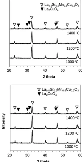
Figure 4 shows the XRD patterns varying the LSMCu
sintering temperature (1000oC, 1200oC and 1400oC). Sin- tering below at 1200oC, LSMCu phase was stably formed without any other products. Otherwise, sintering at 1400oC, La2CuO4, electrically inactive phase, was formed. Figure 5 shows XRD patterns of the YSZ/cathodes interface and impedance spectra of symmetric cell respectively obtained at 700oC~1200oC. The interface by-products between LSMCu cathode and YSZ electrolyte, La2Zr2O7 which has poor oxygen ion conductivity, were formed above 1000oC.
As the higher temperature cathode was sintered, the inter- facial adhesion between electrolyte and electrode became stronger and the ion-exchanging reaction was higher.
Therefore, La2Zr2O7, which was produced above 1200oC, gives stronger effectiveness than increased adhesion in ion exchange reaction of interface.
Figure 6(a) shows the SEM images of the intersections between LSMCu cathode and YSZ electrolyte sintered at 1100oC for 2h. The interlayer reaction by-product layer such as La2Zr2O7 was formed in 1~2 µm thickness. In order to prevent the formation of the interface reaction by-prod- Fig. 4. XRD patterns of LSMCu cathode sintering at 1000oC,
1200oC, and 1400oC.
ucts in the high sintering temperature ranges, thin SDC layer was coated between the cathode and YSZ electrolyte by sol-gel method. In addition, the SDC thin layer coated on pore wall surface of the LSMCu cathode to improve the cathode performance. Figure 6(b) and Figure 6(c) are the SEM microstructure images for the unmodified LSMCu and the SDC-modifed LSMCu cathode, respectively. The SDC thin layer was formed uniformly in 10~30nm thick- ness.
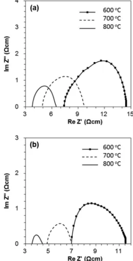
Figure 7 shows impedance analysis of the unmodified LSMCu cathode(a) and the SDC-modified LSMCu cath- ode at 600oC, 700oC, and 800oC, respectively. The half-cell was prepared to analyze the cathode polarization resis- tance. The air was used as a cathode gas. The polarization resistance was significantly decreased in the SDC-modified LSMCu cathode. For the unmodified LSMCu cathode, the polarization resistance was 7.07 Ω·cm2, 4.75 Ω·cm2, and 2.87 Ω·cm2 at 600oC, 700oC, and 800oC, respectively. Oth- erwise, the SDC-modified LSMCu cathode was 4.45 Ω·cm2, 2.01 Ω·cm2, and 0.87 Ω·cm2 at 600oC, 700oC, and 800oC, respectively. The SDC buffer layer between the Fig. 5. XRD patterns of LSMCu cathode/YSZ electrolyte interfaces
after sintering at varying temperatures (900oC~1300oC).
Fig. 6. SEM images of the interlayer reaction by-product forma- tion(a), the unmodified LSMCu cathode(b) and the SDC- modified LSMCu cathode(c).
Fig. 7. Impedance spectra of half cells with the LSMCu cathode(a) and half cells with the SDC-modified LSMCu cathode(b), measured at 600oC, 700oC, and 800oC in air.
cathode and the electrolyte could prevent to form the inter- facial by-products such as La2Zr2O7 or SrTiO3. In addition, the SDC coating on the cathode pore wall makes it possible to form continuous electronic and ionic conducting paths, resulting in expansion of TPB area and low cathode polar- ization. The triple phase boundary can be introduced easily and then the cell performance can be improved by locating electronic path and ionic path independently. Introducing the TPB area in cathode pore wall keeps the pathway of electrons in the cathode and also expands the pathway of the oxygen ion through the SDC thin layers in pore wall.
Thus, the cathode modified by SDC sol can be one of the good candidates for improving performance.
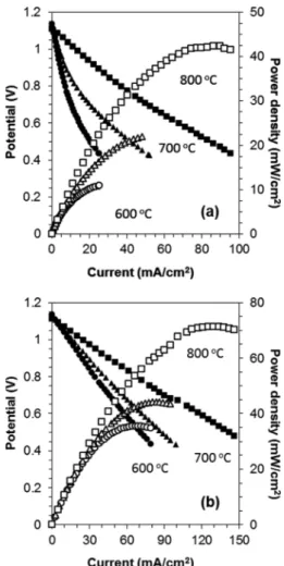
I-V characteristics of the single cell for the unmodified LSMCu cathode(a) and the SDC-modified LSMCu cath- ode(b) were shown in Fig. 8. The cell performance was measured at 600oC, 700oC, and 800oC with 200 ml/min of hydrogen and 200 ml/min air flow for both the LSMCu and the SDC-modified LSMCu cathode. The maximum power densities of the cell with the unmodified LSMCu
cathode were 10.9 mW/cm2, 22.3 mW/cm2, and 42.4 mW/
cm2 at 600oC, 700oC, and 800oC, respectively. Otherwise, those of the cell with the SDC-modified LSMCu cathode were 35.5 mW/cm2, 43.9 mW/cm2, and 71.4 mW/cm2 at 600oC, 700oC, and 800oC, respectively. The cells were improved by introducing SDC diffusion barrier layer and enlarging triple phase boundary. For sintering cathode at 1100oC, decreasing the ionic resistance products such as SrZrO3 or La2Zr2O7 by the SDC interlayer was improved cell performance with around 70%. The ionic conductivity of SDC is better than that of LSMCu and SDC shows MIEC behavior. Therefore, placing the continuous SDC thin layer on the cathode pore wall surface could improve both electronic and ionic properties of the cathode leading electrochemically active for the entire cathode. As the results, additional triple phase boundary can be extended lending improvement of the cell performance by placing the SDC on the cathode pore wall surface.
4. Conclusion
To increase the performance of solid oxide fuel cell oper- ating at intermediate temperature (600oC~800oC), Sm0.2Ce0.8O2 (SDC) thin layer was applied to the La0.8Sr0.2Mn0.8Cu0.2O3 (LSMCu) cathode by sol-gel coating method. The SDC buffer layer was introduced to prevent the interfacial by- product formation between the LSMCu cathode and YSZ electrolyte. The cell performance was improved by mini- mizing the interface reaction product on electrolyte/cath- ode interface. In addition, to enlarge or expand the triple phase boundary from the electrolyte interface and cathode pore surface, the SDC thin layer was applied after sintering cathode by dip-coating method. The interface reaction product such as La2Zr2O7 or SrZrO3 was hardly produced in electrolyte/cathode interlayer by applying SDC layer.
The electrode polarizations were considerably reduced by applying the SDC sol-gel coating on the cathode pore wall.
It was because the ionic conductivity of SDC was better than that of LSMCu. In addition, because SDC coating in LSMCu pore wall added oxygen ion transfer paths, the electrochemical reaction site was enlarged from interface between YSZ electrolyte and LSMCu cathode to LSMCu pore wall. The best performance for minimizing electrode polarization was observed in LSMCu operating at 700oC which was as low as 2.01 Ω·cm2 in air atmosphere. For the single cells modified by sol-gel coating, the maximum power density of the cell was 71.4mW/cm2 with current density of 130 mA/cm2 at 800oC.
Fig. 8. IV-characteristics of single cells with the LSMCu cath- ode(a) and single cells with the SDC-modified LSMCu cathode(b), measured at 600oC, 700oC, and 800oC.
Acknowledgement
This research was supported by a grant (15IFIP-B089065- 02) from Industrial Facilities & Infrastructure Research Program (IFIP) funded by Ministry of Land, Infrastructure and Transport of Korean government.
References
1. B. C. H. Steele and A. Heinzel, “Materials for fuel-cell tech- nologies”, Nature, 414(15), 345 (2001).
2. R. M. Ormerod, “Solid oxide fuel cells”, Chem. Soc. Rev., 32, 17 (2006).
3. J. Nielsen and J. Hjelm, “Impedance of SOFC electrodes : A review and a comprehensive case study on the impedance of LSM:YSZ cathodes”, Electrochim. Acta., 115, 31 (2014).
4. J. Nielsen, T. Jacobsen and M. Wandel “Impedance of porous IT-SOFC LSCF:CGO composite cathodes”, Electrochim.
Acta., 56(23), 7963 (2011).
5. J. Patakangas, Y. Ma, Y. Jing and P. Lund, “Review and anal- ysis of characterization methods and ionic conductivities for low-temperature solid oxide fuel cells (LT-SOFC)”, J. Power Sources, 263, 315 (2014).
6. S. Yi and Y. Joo, “The Improvement of Electrical Character- istics of Inkjet-printed Cu films with Stress Relation during Thermal Treatment”, J. Microelectron. Packag. Soc., 21(4), 57 (2014).
7. D. Kwak, “High Efficiency Power Conversion System of Non Isolated Type Applied in Fuel Cell Generator Used to Fire Prevention Installation”, J. Microelectron. Packag. Soc., 13(3), 19 (2006).
8. K. Hansen and K. V. Hansen, “A-site deficient (La0.6Sr0.4)1−s- Fe0.8Co0.2O3−δ perovskites as SOFC cathodes” Solid State Ion- ics, 178, 1379 (2007).
9. S. D. Souza, S. J. Visco, L. C. D. Jonghe, “Thin-film solid oxide fuel cell with high performance at low temperature”,
Solid State Ionics, 98, 57 (1997).
10. J. W. Stevenson, T. R. Armstrong, R. D. Carneim, L. R. Ped- erson and W. J. Weber, “Electrochemical Properties of Mixed Conducting Perovskites La1−xMxCo1−yFeyO3−δ (M = Sr, Ba, Ca)”, Electrochem. Soc., 143, 2722 (1996).
11. Y. Takeda, R. Kanno, M. Noda, Y. Tomida and O. Yamamoto,
“Cathodic Polarization Phenomena of Perovskite Oxide Elec- trodes with Stabilized Zirconia”, J. Electrochem. Soc., 134, 2656 (1987).
12. S. Sekido, “Electric-ionic conductivity in perovskite-type oxides, SrxLa1-xCo1-yFeyO3-σ”, Solid State Ionics, 37, 253 (1990).
13. V. A. C. Haanappel, A. Mai, and J. Mertens, “Electrode acti- vation of anode-supported SOFCs with LSM- or LSCF-type cathodes”, Solid State Ionics, 177, 2033 (2006).
14. N. Q. Minh, “Ceramic fuel-cells”, J. Am. Ceram. Soc., 76, 563 (1993).
15. D. Y. Wang, D. S. Park, J. Griffith, and A. S. Nowick, “Oxy- gen-ion conductivity and defect interactions in yttria-doped ceria”, Solid State Ionics, 2, 95 (1981).
16. H. L. Tuller and A. S. Nowick, “Doped ceria as a solid oxide electrolyte”, J. Electrochem. Soc., 122, 255 (1975).
17. D. Y. Wang and A. S. Nowick, “The grain-boundary effect in doped ceria solid electrolyte”, J. Solid State Chem., 35, 325 (1980).
18. H. Yahiro, Y. Eguchi, K. Eguchi and H. Arai, “Oxygen ion conductivity of the ceria-samarium oxide system with fluorite structure”, J. Appl. Electrochem., 18, 527 (1988).
19. J. W. Yun, S. P. Yoon, S. Park, J. Han, S.W. Nam, T. H. Lim and J. S. Kim, “Modifying the cathodes of intermediate-tem- perature solid oxide fuel cells with a Ce0.8Sm0.2O2 sol-gel coating”, Int. J. Hydrogen Energy, 34, 9213 (2009).
20. J. W. Yun, J. Han, S. P. Yoon, S. Park, H. S. Kim, and S. W.
Nam, “Ce0.8Gd0.2O2 modification on La0.6Sr0.4Co0.2Fe0.8O3 cathode for improving a cell performance in intermediate temperature solid oxide fuel cells”, J. Ind. Eng. Chem., 17, 439 (2011).