FRP 보강재의 최적 단면 형상 결정 및 평가에 관한 연구
정한구1․ 노인식2,†
군산대학교 조선공학과1 충남대학교 선박해양공학과2
Structural Assessment of the Optimal Section Shape of FRP Based Stiffeners
Han Koo Jeong
1․ In Sik Nho
2,†Department of Naval Architecture, Kunsan National University
1Department of Naval Architecture & Ocean Engineering, Chungnam National University
2Abstract
This paper deals with the structural assessment of metallic and non-metallic stiffened/monocoque plated marine structures under a lateral pressure load to identify appropriate combination of material and section configuration, especially at the preliminary marine structural design stage. A generic rectangular plated structure is exemplified from the metallic superstructure of a marine vessel and its structural topology is varied for the structural assessment. In total 13 different structural topologies are proposed and assessed using appropriate elastic solutions in conjunction with a set of stress and deflection limits obtained from practice. The geometry dimensions and weights of the structural topologies are calculated, and subsequently, the costs of the materials used in the structural topologies are reviewed to discuss the cost-effectiveness of the materials. Finally, conclusions are made with the aim of suggesting suitable structural topology for the marine structural member considered in this paper.
Keywords : Metallic stiffener section shape(금속재료 보강재 단면 형상), FRP stiffener section shape(복합재료 보강재 단면 형상), Optimal section shape(최적 단면 형상), Structural assessment(구조적 평가), Weight effectiveness(중량 효율성), Cost effectiveness(비용 효율성)
1. Introduction
Stiffened plated structures require simple fabrication methods and have good strength to weight ratios. For these reasons, they can easily be found in many engineering transportation as important secondary structural members. A conventional web-frame stiffened metallic plate is a typical example and has extensively been used in transportation industries. Structural topology of this conventional stiffened plate has been varied as advanced manufacturing techniques and new building materials are introduced to marine structures. Non-metallic materials like the FRP (Fibre Reinforced Plastics) composite materials and environment friendly closed manufacturing technique like the VARIM (Vacuum Assisted Resin Infusion Molding) are a case in point. Naturally, these availabilities provide
designers with more choices when they design marine structures especially where structural weight efficiency is critical. Examples of marine structures using FRP based stiffened plated structures are broad (Shenoi & Wellicome, 1993; Mouritz, et al., 2001). Yang, et al. (2005) and Kim, et al. (2010) have investigated the manufacturing aspects of using FRP in marine structures. Eksik, et al. (2007a, b) have carried out experimental as well as numerical work on the FRP based stiffened plates under uniform pressure to assess their strengths and failure modes. Lee, et al. (2009) have studied the dynamic responses of FRP sandwich plated structure using a finite element approach. Shin, et al. (2006) and Ji, et al. (2010) have examined the structural design and analysis aspects of FRP structures in small yachts using finite element approaches.
Therefore, comprehensive structural assessment of
various structural topologies is an important task for
designers at the preliminary structural design stage where the choice of construction materials and the configurations of the stiffened plates can be made before a final decision on the selection of the structural topology. In this assessment, the designers can use appropriate elastic closed-form solutions rather than detailed solutions from finite element analysis.
In this paper, the structural assessment of metallic and non-metallic stiffened/monocoque plated marine structures under a lateral pressure load is performed to identify appropriate combination of material and section configuration. A generic rectangular plate is considered from the metallic superstructure of a marine vessel then its structural topology is varied for the structural assessment.
The proposed various structural topologies include high-strength steel web-frame stiffened plate, aluminium-alloy (AA2011-T6, AA7075-T6) web-frame stiffened plates, CFRP/GFRP top-hat stiffened single skin laminated plates, high-strength steel web-frame stiffened CFRP/GFRP single skin laminated plates, high-strength steel web-frame stiffened CFRP/GFRP sandwich plates, CFRP/GFRP top-hat stiffened sandwich plates and CFRP/GFRP monocoque (un-stiffened) sandwich plates.
For sandwich plates, linear structural PVC foam core is used throughout. Thus, in total 13 different structural topologies are assessed using appropriate elastic closed-form solutions. In the structural assessment, a set of stress and deflection limits obtained from practice is imposed as design constraints, and the geometry dimensions and weights of the structural topologies are calculated to identify an efficient structural topology. After completing the structural assessment, the costs of the materials used in the structural topologies are reviewed using scoring system to discuss the cost effectiveness of the materials. Finally, conclusions are made with the aim of suggesting suitable structural topology for the marine structural members considered in this paper.
2. A Generic Plate
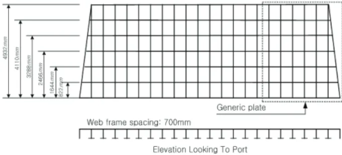
The side plate of the metallic superstructure of a marine vessel is considered as a generic plate in this paper. It is assumed that the side plate has five vertical stiffeners having 700mm spacing, four horizontal stiffeners having 822mm spacing and one bigger horizontal stiffener in the middle of the four horizontal stiffeners. Fig. 1 shows a schematic view of the side of the superstructure and the generic plate represented in dotted rectangle.
For simplicity the generic plate is idealised as a rectangular plate with sets of web-frame type longitudinal and transverse stiffeners. This yields a flat grillage plate having a length of 5m and a width of 4.2m. Furthermore, it is assumed that the plate has simply supported boundary condition and a uniformly distributed pressure load of 5kN/m
2applied to the outer surface of the plate where it is supported by the stiffeners. It should be mentioned that the assumed load of 5kN/m
2is rather low value for the side of the superstructure of a marine vessel in general. However, the size of the superstructure considered in this paper corresponds to the that of a small marine vessel. Thus, it is used throughout the structural assessment performed in this paper.
Fig. 1 A schematic view of the superstructure
3. Various Structural Topologies
The structural topology of the generic plate is varied by including various building materials, stiffening types and construction types. For building materials, high-strength steel, aluminium-alloy, Carbon FRP(CFRP) and Glass FRP(GFRP) are considered; for stiffening types, web-frame stiffener, top-hat stiffener and un-stiffened monocoque type are considered; and for construction types, plate, single skin laminate and sandwich are considered, respectively.
Therefore in total 13 different structural topologies are considered and their basic configurations are shown in Fig.
2. It should be mentioned that, for simplicity, a sectional view of one stiffener with its plate effect breadth is shown in Fig. 2. In Fig. 2, a is flange width, b is flange thickness, c is web thickness, d is stiffener depth excluding b, e is effective breadth, f is plate thickness, f
skinis inner skin thickness, g
coreis core thickness and h
skinis outer skin thickness, respectively.
Definition of 13 different structural topology and their
representative names for the structural assessment are
shown in Table 1.
a
b e
d
f
c
(a)
Dtotal
c = Ct e = Fw
a = Cw d = Dweb
F o rm e r
C F R P /G F R P f = Ft
c = Ct b = Ct
(b)
a
b e
c d
f S i n g l e S k i n L a m i n a t e
(c)
a
b e
d
hs k i n
c
fs k i n gc o r e
(d)
Dtotal
c = Ct e = Fw
a = Cw d = Dweb
F o r m e r fs k i n = Ft
c = Ct b = Ct hs k i n = Ft
gc o r e = Fc
(e)
hs k in
fs k in gc o r e
(f)
Fig. 2 Basic configurations of the structural topologies
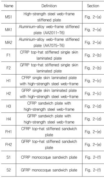
Table 1 Definition of the proposed structural topology
Name Definition Section
MS1 High-strength steel web-frame
stiffened plate Fig. 2-(a) MA1 Aluminium-alloy web-frame stiffened
plate (AA2011-T6) Fig. 2-(a) MA2 Aluminium-alloy web-frame stiffened
plate (AA7075-T6) Fig. 2-(a) F1 CFRP top-hat stiffened single skin
laminated plate Fig. 2-(b) F2 GFRP top-hat stiffened single skin
laminated plate Fig. 2-(b) H1 CFRP single skin laminated plate
with high-strength steel web-frame Fig. 2-(c) H2 GFRP single skin laminated plate
with high-strength steel web-frame Fig. 2-(c) H3 CFRP sandwich plate with
high-strength steel web-frame Fig. 2-(d) H4 GFRP sandwich plate with
high-strength steel web-frame Fig. 2-(d) FH1 CFRP top-hat stiffened sandwich
plate Fig. 2-(e)
FH2 GFRP top-hat stiffened sandwich
plate Fig. 2-(e)
S1 CFRP monocoque sandwich plate Fig. 2-(f)
S2 GFRP monocoque sandwich plate Fig. 2-(f)
4. Solution Procedure
For the structural assessment of the proposed different structural topology, elastic closed-form solutions for the stiffened and un-stiffened monocoque type structural topology are employed in this paper. Brief explanations of these solutions are described below.
4.1 For Stiffened Plate
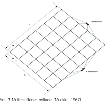
Consider a simply supported rectangular grillage plate as shown in Fig. 3, in which there are s evenly spaced stiffeners in the length l and r evenly spaced stiffeners in the breadth b.
For this plate, a deflection shape can be expressed using a double infinite sine series (Clarkson, 1965;
Muckle, 1967) as follows:
Fig. 3 Multi-stiffener grillage (Muckle, 1967)
∞
∞
(1)
where, m and n are wave numbers and a
mnis coefficient which can be determined by equating the strain energy of bending of the stiffeners to the work done by an applied load. The strain energy of one longitudinal and one transverse stiffener can be written as follows:
(2)
where, E is elastic modulus, and I
rand I
sare the second moment of area of the longitudinal and transverse stiffeners. The values of x and y used in Eq. (2) can be corresponded to the particular stiffener such as the p
thlongitudinal, y
p, and q
thtransverse, xq, stiffeners.
(3)
(4)
Thus, by substituting Eqns. (1), (3) and (4) into Eq. (2), one can obtain total strain energy for all stiffeners as follows:
∞
∞
∞
∞
(5)
If the load P per unit area is acting on the grillage plate then the work done by P can be defined as follows:
(6)
Now the general coefficient a
mncan be determined by equating Eqns. (5) and (6), and if P has uniform load distribution then the coefficient a
mnfor this particular form of loading becomes,
(7)
Therefore the complete expression of the deflection of the grillage plate can be obtained by substituting Eq. (7) into Eq. (1). Finally the tensile and compressive stresses of the p
thlongitudinal and q
thtransverse stiffeners can be calculated by using the following bending moment equations.
For the p
thlongitudinal stiffener:
(8)
For the q
thtransverse stiffener:
(9)
4.2 For Un-stiffened Plate
For a simply supported rectangular un-stiffened plate
such as a monocoque sandwich plate, anisotropic
laminated plate theories such as Classical Laminated Plate
Theory(CLPT) (Whitney, 1987) and Higher-order Shear
Deformation Theory(HSDT) (Reddy, 1984; Khdeir, et al.,
1987; Khdeir & Reddy, 1989) can be used. CLPT is more
economic in solution procedure than HSDT. However
when shear and compression effects due to the
interaction between stiff thin skin laminates and flexible
thick core in the plate through-thickness direction are
considered, CLPT produces less accurate results than
HSDT does. For this reason, HSDT based approach is
employed in this paper. The mathematical deflection and
stress expressions of the sandwich plate are obtained by
using a simplified higher-order shear deformation theory (Reddy, 1984) for an anisotropic laminated plate by considering the material properties and geometry values of the sandwich plate. This theory can take into account not only transverse shear strains but also parabolic variations of the transverse shear strains with respect to the plate thickness direction. By considering that the transverse shear strains and the corresponding transverse shear stresses vanish on the top and bottom of the sandwich plate, the following displacement field equations are proposed,
(10)
(11)
(12) where u, v, w are in-plane and transverse displacements ( u
0, v
0and w
0denote the same notation at middle-plane), and
,
are rotations of normal to sandwich plate mid-plane about y and x axes, and h is sandwich plate height. x, y and z are the Cartesian coordinates of sandwich plate.
The principle of virtual displacements is used to obtain equilibrium equations pertinent to both the displacement field equations, Eqns. (10), (11) and (12), and stress-strain constitutive equations, Eqns. (13) and (14).
(13)
(14) where
are stress/strain components, and
are elastic moduli based matrix elements (Agarwal & Broutman, 1990). 5 equilibrium equations in the domain of the sandwich plate mid-plane are derived for 5 displacement coefficient terms as follows:
(14) where
are stress/strain components, and
are elastic moduli based matrix elements (Agarwal & Broutman, 1990). 5 equilibrium equations in the domain of the sandwich plate mid-plane are derived for 5 displacement coefficient terms as follows:
(15)
(16)
(17)
(18)
(19)
where
are equal to
and
are equal
to
, respectively.
An exact Navier-type solution procedure (Chia, 1980) is used to solve the equilibrium equations of the sandwich plate. The following double infinite sine series solutions are assumed for w,
and
satisfying the simply supported boundary condition.
∞
∞
(20)
∞ ∞
(21)
∞
∞
(22)
The coefficients, W
mn, X
mnand Y
mnin these assumed solutions are determined by substituting Eqns. (17), (18), (19) and stress resultant equations,
, for a sandwich plate
having symmetry into Eqns. (20), (21) and (22).
5. Structural Assessment
As mentioned previously, the given number of vertical and horizontal stiffeners and spacings are for metallic construction materials. Therefore when non-metallic materials such as CFRP and GFRP are considered as construction materials, an altered number of stiffeners and spacings needs to be used. To derive a suitable number of stiffeners and spacings, which can be applied to the proposed 13 structural topologies, the scantling calculation of selected structural topology is performed.
In this calculation, various stiffener spacing values with one nominal depth of 80mm are considered that fit to the generic plate size of 5m×4.2m as follows:
- Longitudinal stiffener spacing values are 1050mm, 840mm and 600mm representing 3, 4 and 6 longitudinal stiffeners.
- Transverse stiffener spacing values are 1000mm, 625mm and 500mm representing 4, 7 and 9 transverse stiffeners.
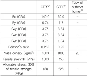
CFRP/GFRP top-hat stiffened single skin laminated plates are selected for the scantling calculation to determine suitable stiffener spacing values based on the above information. Material properties for CFRP, GFRP and top-hat stiffener former with allowable stresses are shown in Table 2. The allowable stresses are defined as 30% of respective material's ultimate tensile strengths.
In the calculation, the following assumptions are made based on the measuring experience of GFRP top-hat stiffened single skin laminated plate supplied by a manufacturer.
- Thickness of top-hat webs, c, of longitudinal and transverse stiffeners is equal to the thickness of top-hat flanges, b, of longitudinal and transverse stiffeners, respectively.
- Effective breadth, e, of longitudinal and transverse stiffeners is equal to 20% of their corresponding stiffener spacing.
- Width of top-hat flanges, a, of longitudinal and transverse stiffeners is equal to 30% of their corresponding stiffener effective breadth, e.
- Thickness of single skin plate, f, is equal to three times of top-hat web thickness, c.
Table 2 Material properties used for CFRP/GFRP top-hat stiffened single skin laminated plates
CFRP
+GFRP
#Top-hat stiffener former
@Ex (GPa) 140.0 30.0 -
Ey (GPa) 6.74 7.7 -
Gxy (GPa) 3.75 3.34 -
Gxz (GPa) 3.75 3.34 -
Gyz (GPa) 3.75 1.34 -
Poisson’s ratio 0.282 0.25 -
Mass density (kg/m
3) 1600 1800 20 Tensile strength (MPa) 1500 750 - Allowable stress, 30%
of tensile strength (MPa)
450 225 -
+
: Carbon/Epoxy high-strength unidirectional laminate
#
: E-glass/Polyester unidirectional laminate
@
: Non-structural former
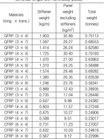
It should be mentioned that the FRP based structural topology in this paper is assumed as monolithic. Hence only a thickness value and weight metrics are derived and no attempt is made to ascribe this in terms of ply details, make-up, fibre volume fractions etc. It can be debated that this could be taken up at a later stage after gross decisions about the choice of particular structural topology and construction material are made. Calculation results are shown in Table 3. From this, it is found that 6×9 grillage option produces the lightest total weight, while 3×4 grillage option produces the heaviest total weight for both GFRP and CFRP construction materials.
Therefore, 6×9 grillage option with one nominal depth of 80mm is chosen and applied to all the remaining structural topology to obtain their weight metrics. Material properties for steel, aluminium alloys and sandwich core with allowable stresses are shown in Table 4. Again, the allowable stresses are defined as 30% of respective material's ultimate tensile strengths.
Like the calculations of the CFRP/GFRP top-hat
stiffened single skin laminated plates, similar assumptions
are made for the calculations of the remaining structural
topologies. It should be mentioned that in assigning these
assumptions, the assumptions made for the FRP top-hat
stiffened single skin laminated plates are used as a basis
for the purpose of equivalent structural assessment. As a
result, some assumptions, especially for metallic web-frame
stiffened plates (MS1, MA1, MA2), can be unusual from
normal practice viewpoint (i.e. the same thickness of web and flange, 20% of stiffener spacing as effective breadth).
These assumptions are summarized in Table 5.
Table 3 Calculation results of the CFRP/GFRP top-hat stiffened single skin laminated plates
Materials (long. × trans.)
Stiffener weight (kg/m)
Panel weight excluding stiffeners (kg/m
2)
Total weight (tonnes)
GFRP (3 × 4) 1.903 32.89 0.75113
GFRP (3 × 7) 1.597 29.27 0.68553
GFRP (3 × 9) 1.414 26.24 0.62580
GFRP (4 × 4) 1.725 30.40 0.70193
GFRP (4 × 7) 1.470 27.00 0.63963
GFRP (4 × 9) 1.310 24.25 0.58488
GFRP (6 × 4) 1.574 29.48 0.69282
GFRP (6 × 7) 1.380 26.35 0.63539
GFRP (6 × 9) 1.246 23.76 0.58341
CFRP (3 × 4) 0.889 12.43 0.28935
CFRP (3 × 7) 0.735 11.04 0.26446
CFRP (3 × 9) 0.647 9.98 0.24382
CFRP (4 × 4) 0.803 11.57 0.27249
CFRP (4 × 7) 0.675 10.27 0.24906
CFRP (4 × 9) 0.599 9.31 0.23017
CFRP (6 × 4) 0.731 11.23 0.27007
CFRP (6 × 7) 0.632 10.03 0.24819
CFRP (6 × 9) 0.567 9.12 0.22996
Table 4 Material properties used for metallic structural topology and sandwich core
Steel
+AA 2011-T6
AA 7075-T6
Sandwich core
#E (GPa) 210.0 71.0 72.0 0.1092
G (GPa) 80.8 26.0 26.9 0.0298
Poisson’s
ratio 0.3 0.33 0.33 0.32
Mass density (kg/m
3)
7850.0 2820.0 2800.0 92
Tensile strength
(MPa)
880.0 395.0 550.0
1.0 (shear strength) Allowable
stress, 30%
of tensile strength
(MPa)
264.0 118.5 165.0
0.3 (30%
of shear strength)
+
: High-strength steel
#
: Linear structural PVC foam core
Table 5 Assumptions for the structural topologies (except for F1 and F2)
Name Common Specific
MS1 - Thickness of (top-hat) webs, c, of longitudinal and transverse stiffeners is equal to the thickness of (top-hat) flanges, b, of longitudinal and transverse stiffeners, respectively.
- Effective breadth, e, of longitudinal and transverse stiffeners is equal to 20% of their corresponding stiffener spacing.
- Width of (top-hat) flanges, a, of longitudinal and transverse stiffeners is equal to 30% of their corresponding stiffener effective breadth, e.
- Thickness of plate, f, is equal to web thickness, c.
MA1 MA2 H1 H2
H3 - Thickness of the inner,
f
skin, and outer, h
skin, skins are the same and they are equal to 50%
of web thickness, c (H3
& H4).
- Thickness of the inner, f
skin, and outer, h
skin, skins are the same and they are equal to top-hat web thickness, c (FH1 & FH2).
- Thickness of the core, g
core, is equal to 400%
of (top-hat) flange thickness, b.
H4
FH1
FH2
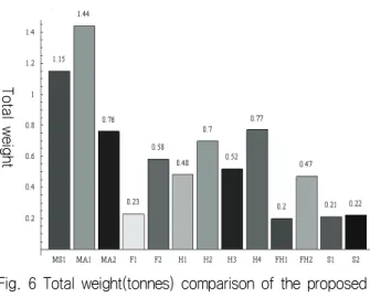
All the calculation results are shown in Table 6 and they are also graphically represented in Figs. 4, 5 and 6. In the case of the CFRP/GFRP monocoque sandwich plates, maximum deflection design limit is used independently in addition to the allowable stress design limit. This is because when the allowable stress design limit is only used, impractical skin thickness is obtained. Thus to obtain practical skin thickness, the calculations are performed based on the maximum deflections of the CFRP/GFRP top-hat stiffened single skin laminated plates as design limits: the results show that practical skin thickness can be obtained.
It is revealed that the monocoque sandwich plate option
is a lighter option than the FRP top-hat stiffened single
skin laminated plate options, see Table 6 and Fig. 6. Total
weight of both CFRP and GFRP sandwich plates is slightly
less than that of the CFRP top-hat stiffened single skin
plate. Between the CFRP and GFRP monocoque sandwich
plates, the difference in total weight is not noticeable due
to thin skin thickness under the present design constraints
– the maximum deflection based limits.
Table 6 Calculation results of the proposed 13 structural topologies
Name Stiffener weight (kg/m)
Panel weight excluding stiffeners (kg/m
2)
Total weight (tonnes)
MS1 4.16 41.13 1.15
MA1 3.99 55.55 1.44
MA2 2.55 27.83 0.76
F1 0.57 9.12 0.23
F2 1.25 23.76 0.58
H1 4.38 8.90 0.48
H2 5.90 14.13 0.70
H3 3.70 12.73 0.52
H4 3.92 24.11 0.77
FH1 0.57 7.46 0.20
FH2 1.08 19.09 0.47
S1 0.00 10.16 0.21
S2 0.00 10.37 0.22
Fig. 4 Stiffener weight(kg/m) comparison of the proposed structural topology
Fig. 5 Panel weight(kg/m2) comparison of the proposed structural topology
Fig. 6 Total weight(tonnes) comparison of the proposed structural topology
Apart from the CFRP/GFRP monocoque sandwich plate options, the structural assessment of the other structural topologies is performed based on the allowable stress design limit as intended. The results show that the CFRP top-hat stiffened sandwich plate is the lightest option followed by the CFRP monocoque sandwich plate, the GFRP monocoque sandwich plate, the CFRP top-hat stiffened single skin laminated plate and so on. Interestingly, the aluminium-alloy (AA2011-T6) web-frame stiffened plate is the heaviest option. It is judged that this is happened because AA2011-T6 has the lowest tensile strength value (Table 4) which results in very heavy plating (Table 6).
In general, the high-strength steel and aluminium-alloy based plate options are heavier than the CFRP and GFRP based plate options. Also it is found that the CFRP plate options are lighter than the GFRP plate options.
For the stiffening types, the web-frame stiffener option is heavier than the top-hat stiffener option regardless of the CFRP and GFRP construction materials. This finding can be applied to the single skin laminated plate and monocoque sandwich plate as well.
6. Material Costs
After completing the structural assessment of the proposed structural topologies, the costs of their construction materials are reviewed by using a 'score' of value 0 to 4. This scoring system is used instead of actual costs because the costs of some materials are difficult to define. Between metallic and FRP materials, FRP materials tend to show more inconstancy in costs due to the rapid increment of engineering applications adopting them, especially for CFRP. Thus the 'score' values are defined by
P a nel w eig ht e xc lu di ng st iff ener s S tiffe n er w eig ht Tot a l w eig ht
experts from marine industries in both metallic and FRP construction environment based on their work experiences.
A definition of each score is provided in Table 7.
'No issues' means that there is no effect on selecting the construction material to overall design and a value of '0' is applied. 'Major' means that there will be significant effect on selecting the construction material to overall design and a value of '4' is given. Between these two extreme scores, a further division is made by introducing three scores as 'Minor', 'Limited', 'Extensive', and values of 1, 2, 3 are assigned, respectively. It is convenient to see the scores 0 to 4 as weighting factors based on the cost of the construction material of each structural topology.
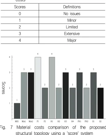
Score values are given for the proposed structural topologies and these are graphically represented in Fig. 7.
As it can be seen, the CFRP single skin laminated plate options are assigned the highest value of 4 and the high-strength steel web-frame stiffened plate option is given the lowest value of 1. From the aspect of high to low scoring, the construction materials can be arranged in the order of CFRP, aluminium-alloy, GFRP and high-strength steel. For the CFRP based structural topology, the sandwich plate options are given a lower value than the single skin laminated plate options because the sandwich plate options use less CFRP material.
Table 7 Definitions of scores for the construction material costs
Scores Definitions
0 No issues
1 Minor
2 Limited
3 Extensive
4 Major
Fig. 7 Material costs comparison of the proposed structural topology using a 'score' system
7. Conclusions
This paper endeavors to produce useful information for marine designers especially at the preliminary structural design stage where the choice of construction materials and stiffener section configurations for stiffened marine structural member can be made. A generic rectangular plated structure is exemplified from the metallic superstructure of a marine vessel and its structural topology is varied for the structural assessment. In total 13 different structural topologies are proposed as alternative structural forms for the generic plate. Comprehensive structural assessment of these structural topologies is performed based on the derived number of longitudinal and transverse stiffeners which produces the lightest stiffened plate weight.
Through this assessment, weight efficient structural topology, consisted of construction materials, and plate and stiffener types, are identified.
In the structural assessment, only a uniformly distributed pressure load is assumed for the stiffened plated structures because this is a representative load case for a marine structure. It should be mentioned that, however, an in-plane load case inducing buckling to the stiffened plated structures needs to be incorporated in the structural assessment as structural design spiral progresses. Also, a simply supported boundary condition is assumed for the simplicity in solution procedures and this needs to be extended by considering a clamped boundary condition to closely represent the stiffened plated structures in practice as structural design moves on. The closed-form solution used in this paper for the stiffened plated structures is simple and effective. However this solution becomes restrictive to use when it encounters various boundary conditions and applied load cases. Therefore, based on the outcome obtained in this paper, it is suggested to use more versatile solutions such as finite element solutions to the stiffened plated structures when marine designers need more detailed information than outcome obtained in this paper.
After completing the structural assessment, the costs of the construction materials used in the proposed structural topologies are reviewed by using a 'score' system. Because of inconstancy in costs for some construction materials, the 'score' values defined by experts from marine industries in both metallic and FRP construction environment are adopted to briefly review the cost-effective aspect of the construction materials.
Sc o re s
In conclusion, the FRP based structural topology is favourable to marine structures from the structural assessment viewpoint conducted in this paper, and this is especially true for the CFRP based structural topology.
Metal, especially high-strength steel, based structural topology is also favourable to marine structures from economic material cost viewpoint. It should be stressed that there are other important issues affecting the selection of structural topology advantageous to marine structures such as corrosion resistance, maintenance and other 'through-life' costs. If these issues are factored into the overall outcome obtained in this paper then it may be that the FRP based structural topology becomes a very attractive proposition.
Acknowledgement
The work described in this paper was supported by National Research Foundation of Korea Grant funded by the Korean Government (2009-0083828). The authors wish to thank their support.
References
Agarwal, B.D. Broutman, L.J., 1990. Analysis and performance of fibre composites, John Wiley & Sons, Inc.
Chia, C.Y., 1980. Nonlinear analysis of plates, McGraw-Hill Book Company.
Clarkson, J., 1965. The Elastic Analysis of Flat Grillages.
Cambridge University Press.
Eksik, O. Shenoi, R.A. Moy, S.S.J. & Jeong, H.K., 2007a. Experiments on Top-hat-stiffened Panels of Fiber-Reinforced-Plastic Boat Structures. Marine Technology, 44(1), pp.1-15.
Eksik, O. Shenoi, R.A. Moy, S.S.J. & Jeong, H.K., 2007b. Finite Element Analysis of Top-hat-stiffened Panels of Fiber-Reinforced-Plastic Boat Structures, Marine Technology, 44(1), pp.16-26.
Ji, S.H. Roh, J.S. Kang, S.W. Kim, H.W. & Kim, M.H., 2010. Structural Safety Evaluation of 40 Feet Sailing Yacht by Computational Structure Analysis. Journal of the Society of Naval Architects of Korea, 47(5), pp.703-708.
Khdeir, A.A. & Reddy, J.N., 1989. Exact Solutions for the Transient Response of Symmetric Cross-ply Laminates using a Higher-order Plate Theory. Composites Science and Technology, 34(3), pp.205-224.
Khdeir, A.A. Reddy, J.N. & Librescu, L., 1987. Analytical Solution of a Refined Shear Deformation Theory for Rectangular Composite Plates. International Journal of Solids and Structures, 23(10), pp.1447-1463.
Kim, D.D.W. Hennigan, D.J. & Beavers, K.D., 2010.
Effect of Fabrication Processes on Mechanical Properties of Glass Fiber Reinforced Polymer Composites for 49 meter (160 foot) Recreational Yachts.
International Journal of Naval Architecture and Ocean Engineering, 2(1), pp.45-56.
Lee, S.J. Song, J.H. & Hong, S.Y., 2009. Applications of Spectral Finite Element Method for Vibration Analysis of Sandwich Plate with Viscoelastic Core. Journal of the Society of Naval Architects of Korea, 46(2), pp.155-164.
Mouritz, A. Gellert, E. Burchill, P. & Challis, K., 2001.
Review of Advanced Composite Structures for Naval Ships and Submarines. Composite Structures, 53(1), pp.21-41.
Muckle, W., 1967. Strength of Ships’ Structures. Edward Arnold (Publishers) Ltd., London
Reddy, J.N., 1984. A Simple Higher-Order Theory for Laminated Composite Plates. Journal of Applied Mechanics, 51, pp.745-752.
Shenoi, R.A. Wellicome, J.F., 1993. Composite Materials in Marine Structures, Cambridge University Press.
Shin, J.G. et al., 2006. A Study on the Structural Design and Structural Analysis for Small Yacht. Journal of the Society of Naval Architects of Korea, 43(1), pp.75-86.
Whitney, J.M., 1987. Structural Analysis Of Laminated Anisotropic Plates. Technomic Publishing Company, Inc.
Yang, J.M. Ha, Y.S. & Kim, H.C., 2005. Production Method of FRP Boat Using Developable Surface without a Mould. Journal of the Society of Naval Architects of Korea, 42(5), pp.506-515.
정 한 구 노 인 식