Easy Identification of Mechanical Axis during Total Knee Arthroplasty
Jai-Gon Seo,
1Young-Wan Moon,
1Sang-Min Kim,
1Byung-Chul Jo,
1and Sang-Hoon Park
21Department of Orthopaedic Surgery, Samsung Medical Center, Sungkyunkwan University School of Medicine, Seoul;
2Department of Orthopaedic Surgery, National Health Insurance Service Ilsan Hospital, Goyang, Korea.
Received: July 12, 2012 Revised: October 18, 2012 Accepted: January 11, 2013
Corresponding author: Dr. Sang-Hoon Park, Department of Orthopaedic Surgery, National Health Insurance Service Ilsan Hospital, 100 Ilsan-ro, Ilsandong-gu, Goyang 410-719, Korea.
Tel: 82-31-900-0540, Fax: 82-31-900-0343 E-mail: [email protected]
∙ The authors have no financial conflicts of interest.
© Copyright:
Yonsei University College of Medicine 2013 This is an Open Access article distributed under the terms of the Creative Commons Attribution Non- Commercial License (http://creativecommons.org/
licenses/by-nc/3.0) which permits unrestricted non- commercial use, distribution, and reproduction in any medium, provided the original work is properly cited.
Purpose: We devised an intraoperatively identifiable mechanical axis (IIMA) as a reference of alignment in total knee arthroplasty (TKA). Materials and Methods:
Between February 2010 and January 2011, primary TKAs were consecutively per- formed on 672 patients (1007 knees) using an IIMA as a reference in the coronal plane. Results: The alignment of the lower extremity improved from a mean of 11.4±6.7° (-10.3-34.4°) of varus preop. to 0.7±3.5° (-5.2-8.6°) immediately after surgery. Mean alignment of the femoral component in the coronal plane was 89.3±2.3° (83.4-97.2°) postop. and mean alignment of the tibial component was 90.4±2.2° (85.1-94.2°) postop. Conclusion: This study showed that IIMA could be of considerable value as a new guider of alignment that is easily accessible and highly effective during total knee arthroplasty.
Key Words: Lower limb neutral mechanical axis, inter-femoral head center dis- tance, extramedullary reference, total knee arthroplasty
INTRODUCTION
Mal-alignment and inappropriate component position during total knee arthroplas- ty (TKA) can cause instability and loosening, and it is one of the most important surgical errors that lead to clinical failure after TKA.1-6 Therefore, accurate assess- ment of lower extremity alignment and component positioning are regarded as the most important factor of long-term successful clinical outcome.2,4,5,7,8 The mechan- ical axis of the lower extremity is the basis of alignment during TKA. During pre- operative and postoperative radiologic planning, it is easy and common to use me- chanical axis of the lower extremity as the basis for alignment evaluations. However, it is difficult to determine the mechanical axis during surgery. As a result, various techniques have been developed to achieve proper alignment. In terms of lower extremity alignment, conventional techniques depend on the medullary canal tech- nique. The extramedullary (EM) technique and navigation system are based on find- ing the femoral head center.1,9-15 The conventional intramedullary technique uses the femoral medullary canal as its reference. However, determining the mechanical axis using intramedullary technique have been reported to result in 5-30% malalignment rate.2,5,11 This is mainly due to canal deformity and variations which are frequent in
center line (H-line). We were able to confirm the lower limb mechanical axis during operation using IIMA. Furthermore, precision was increased and consistency could be main- tained since the mechanical axis could easily be confirmed at any time during surgery.
The purpose of this study was to introduce our new EM alignment guide system and to report radiologic outcome observed in a large-volume total knee practice when the neutral mechanical axis of the overall lower limb was used as a reference.
MATERIALS AND METHODS
IIMA setting method
We devised IIMA using the body center line and inter-fem- oral head center line (H-line) (Fig. 1). There are two me- chanical axes that are parallel to body center line. We could measure the length of inter-femoral head center distance with radiograph. Body center line can be defined by a line connecting xiphoid process and symphysis pubis. With the two known factors, H-line and body center line, we could construct the mechanical axis that is parallel to the body center line.17,18
Inter femoral head center distance is constant and bisect- ed perpendicularly by body center line. H-line can be repli- cated on the ruler with two markers. We could get IIMA by connecting the end of replicated inter femoral head center lines located proximally and distally (Fig. 1).
The instruments for IIMA system are composed of two parts. One is proximal ruler and frame and the other is dis- tal ruler (Fig. 2).
The inter-femoral head distance (H-line) in the calibrated radiograph was checked with magnetic bar and the distance on the ruler with two markers was replicated (Fig. 3). Then the center of the ruler was placed on the body center line perpendicularly (Fig. 4). The proximal ruler and frame were set above the hip center and the distal ruler below the ankle center. And ipsilateral proximal-distal markers were connected with a Bovie line then the IIMA can be visible on the operation-field (Fig. 5).
Subjects
One thousand and seven patients (1007 knees) who under- went primary TKA consecutively using IIMA by a surgeon from February 2010 to January 2011 constituted the study cohort. This study was approved by the Institutional Re- the femur. As for extramedullary technique for the femoral
bone resection, it relies on identifying the center of femoral head during surgical procedure. Although various techniques have been introduced such as the use of the pelvic anterior superior iliac spine or femoral artery as landmark to pinpoint femoral head center, these techniques have been abandoned because of increase in surgical times.1,16-18 In order to deter- mine the femoral head center, it took much more compli- cated surgical procedure and increased cost with less accu- rate result of final lower limb alignment.1,10,17,18
We devised intraoperatively identifiable mechanical axis (IIMA) using the body center line and inter-femoral head
Fig. 1. Proximal and distal coronal mechanical axis markers are located above the femoral head and the ankle center. Mechanical axis can be identified by the line which connects the two mechanical axis markers.
Fig. 2. Instruments for IIMA system is composed of two parts. Proximal part has ruler and frame with markers and distal part ruler has the same struc- ture to that of proximal ruler. IIMA, intraoperatively identifiable mechanical axis.
then EM axis guider was used to adjust femur’s coronal axis and sagittal alignment for synchronization.16 Proximal tibial cuts were made using an EM alignment guide (Link- er®), an instrument that maintains a parallel status between the femoral and tibial mechanical axes.17,18 The patella was routinely resurfaced, and all implants were fixed with ce- ment.
Radiologic evaluations
During radiologic evaluations, the mechanical axis was pre- operatively measured using an orthoroentgenogram and 2 view Board. All patients underwent either bilateral or uni-
lateral TKA. Average patient age was 68 years (57-79) and 896 knees had degenerative arthritis, 88 osteonecrosis, and 23 rheumatic arthritis. There were 351 bilateral patients and 305 unilateral cases. Patients with unacceptable conditions to use ruler and frame such as pelvic or hip deformity were excluded. And revisional TKA and infection cases were also excluded. A single Scorpio® NRG implant (Stryker, Mahwah, NJ, USA) was inserted using extramedullary technique.
Operative procedures
Modified antero-medial parapatellar incision of Insall was used to make an approach. After soft tissue balancing, ex- tramedullary technique was used to install distal femoral block. The connector to which proximal tibial resector was attached was inserted into distal femoral resector’s slot, and
Fig. 3. (A) Distance between femoral head centers (H-line) is measured on radiographs. H-line is bisected perpendicularly by the body center line. (B) H-line can be replicated on a ruler with two markers.
Fig. 4. The center of the ruler was located on the body center line which connects the xiphoid process and the symphysis pubis. Inter-femoral head center distance is bisected perpendicularly by the body center line.
Fig. 5. Replicated H-line with two markers are shown proximal to the hip center and distal to the ankle center. Conjoined marker with visible line constitute mechanical axis that is parallel to the body center line. (A) IIMA and pre-op. limb alignment is illustrated. (B) Correct limb alignment can be confirmed when the hip, knee and ankle ccenters are located on the IIMA.
(C) After cementing of total knee components, whole limb alignment can be compared to the visualized mechanical axis (Bovie line). IIMA, intraop- eratively identifiable mechanical axis.
A
B
A B C
cases) and at 95.4% (967/1007 cases), respectively. No ma- jor postoperative complications, such as deep infection, stiffness, or a cardiopulmonary complication, were encoun- tered. The ICC about intra-observer variability was 0.89, and ICC about inter-observer variability was 0.86. There was good or excellent inter-observer agreement in all of the measurements performed.
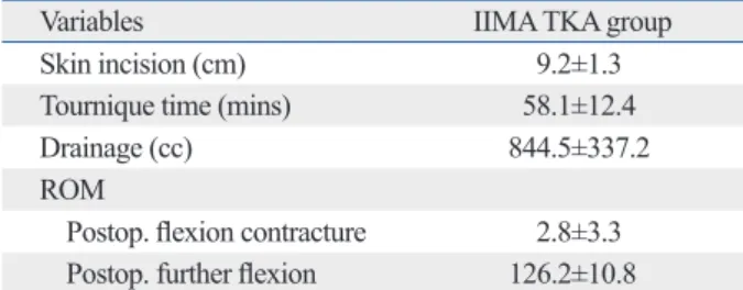
Skin incision at the time of surgery was 9.2±1.3 cm (7.5- 13), and operation time was 58.1±12 min (48-103). Postop- erative blood drainage was 844.5 mL (250-1995) (Table 2).
There was no deep infection, however superficial wound in- fection in 2 cases. Marginal wound necrosis less than 1 cm occurred in 5 cases, and wound oozing lasting more than 1 week occurred in 16 cases. However, there were no compli- cations which needed further surgical intervention. Regard- ing ROM of postoperative 2 months, average was 2.8- 126.2°. Clinical outcomes such as WOMAC score and KSS score have been improved (Table 3).
DISCUSSION
Precision of the coronal alignment has increased and con- sistency can be maintained since the mechanical axis can easily be confirmed at any time during surgery. In our co- hort, outliers of femoral and tibial components were only 7.7% and at 4.6% respectively, with IIMA setting.
Alignment of the mechanical axis of the lower extremity and appropriate location of components are important fac- tors in total knee arthroplasty.8,15,19,20 Many studies have been conducted for the precision of lower extremity align- ment because mal-alignment is a main factor of failure after TKA and causes early component loosening and instability.
Measurements of the mechanical axis of the lower extremi- ty in the coronal plane in pre- and postoperative radiographs have been proposed for the evaluation of alignments. In ad- dition, it has been reported that the longevity of TKA is in- creased when bone resection and component insertion are carried out using the mechanical axis as a basis.2,6,12,13,21
Current trends of improving alignment also include reduc- ing outliers, and error margins. Intramedullary technique is months postoperatively. In addition, the angles of the femo-
ral and tibial components in the coronal plane were mea- sured in front and rear knee joint X-ray. Orthoroentgeno- grams were taken such that the radiolucent line was vertical to the knee joint plane when the patient stretched the knee joint to its fullest and bore weight equally on lower extrem- ities. Error margins of the femoral and tibial components in the coronal plane were defined as above 3° from the me- chanical axis.
Intraclass Correlation Coefficients (ICC) were used to identify agreement degree within a rater or between raters.
Three independent observers measured coronal alignment of the component (KLK, KHL, and JWH).
RESULTS
The mean deflection of the mechanical axis of the lower extremity improved from a mean 11.4±6.7° (-10.3-34.4°) of preoperative varus deformity to 0.7±3.5° (-5.2-8.6°) after the operation. Postoperative mean alignment of the femoral and tibial components in the coronal plane were 89.3±2.3°
(83.4-97.2°) and 90.4±2.2° (85.1-94.2°), respectively (Ta- ble 1). The femoral and tibial components in the coronal plane had error margins of within 3° at 92.3% (903/1007 Table 1. Radiologic Alignment of Components
Parameters Preop. Postop. p value
Mechanical femorotibial angle (°) Varus 11.4±6.7 Varus 0.7±3.5 <0.01
Femoral coronal medial angle (°) 89.3±2.3 89.3±2.3 <0.01
Tibial coronal medial angle (°) 89.5±2.2 90.4±2.2 <0.01
Data are presented as means with standard deviation.
Table 2. Postoperative Parameters
Variables IIMA TKA group
Skin incision (cm) 9.2±1.3
Tournique time (mins) 58.1±12.4
Drainage (cc) 844.5±337.2
ROM
Postop. flexion contracture 2.8±3.3 Postop. further flexion 126.2±10.8 IIMA, intraoperatively identifiable mechanical axis; TKA, total knee arthro- plasty.
Table 3. Clinical Scoring
Parameters Preop. Postop. p value
KSS knee score 42.8 90.1 <0.01
KSS functional score 52.1 89.8 <0.01 Postoperative
WOMAC score 57.1 28.1 <0.01
vivid contrast to other conventional results with ranges of around 15-40%.7,10,16,23,26
Furthermore, the procedure is highly cost-effective, straightforward, and convenient.
The use of the IIMA could be regarded as an adjuvant to intramedullary or extramedullary TKA. The IIMA can be used as the basis of osteotomy or implant alignment at any time of operation, and it can easily be utilized during sur- gery. Also, IIMA can easily be applied to detect the amount of errors when mal-alignment is suspected. Furthermore, the IIMA can be used for high tibial osteotomy and other procedures, in addition to TKA.
Looking into the trait of IIMA, mechanical axis can be changeable with lower leg position, but there are only two mechanical axes parallel to the body center line. A line that connects the femoral head centers (H-line) is bisected verti- cally by the body center line. When we replicate the H-line on the ruler with markers and place it proximally and distal- ly to the hip center and the ankle center respectively, we can trace the mechanical axis by connecting ipsilateral markers with a bovie line. IIMA is the only mechanical axis that is parallel to the body center line. The greatest advantage of IIMA is that it can be set preoperatively and applied to con- firm the alignment on every step of operation. In the present study, satisfactory alignment in coronal plane was achieved using IIMA, and outliers were minimized.
Since the purpose of this study was to introduce IIMA, and to evaluate the radiological outcome of immediate post operation, long-term evaluation is not available at this mo- ment, and we did not consider the range of motion, and knee joint pain after surgery or clinical results. Furthermore, the study is also limited because of lack of a comparison be- tween surgery with and without IIMA by the same surgeon.
It was retrospectively consecutive and there is no compara- tive study. The limitations of using IIMA method are as fol- lows: pelvic deformities that prevent precise estimation of inter head center distance and hip deformities such as se- quellae of cerebral palsy, poliomyelitis, and Legg-Calve- Perthes disease etc. Nevertheless, this is a large-volume study and satisfactory radiological results in the coronal plane were achieved.
IIMA can be considered as a new alternative alignment guider that is easily accessible and highly effective.
In conclusion, by applying IIMA as the basis of align- ment for bone cutting and implant location during total knee arthroplasty, satisfactory radiological results in the coronal plane were achieved.
the most common way, nevertheless the rates of outliers re- portedly range from 10% to 20%.1,11,21-23
There are many alignment techniques currently used. First, the intramedullary technique using the femoral canal as a guide. Intramedullary guides rely on a proper fit in the in- tramedullary canal. It is often difficult to achieve the proper mechanical axis due to diaphyseal deformity, distortion of the osseous canal, residual implants from previous surgery, malunited fractures, metabolic bone disease, and variations in femoral anatomy such as a large intramedullary canal and excessive femoral bowing.9,22,24 Second, the conventional extramedullary technique or navigation technique that uses the femoral head center as reference. Techniques referenc- ing the femoral head center were the first to use the mechan- ical axis, however, it suffers from precision issues regarding the consistency of surface marker placement especially in obese patients. In addition, the marker position could be mo- bilized due to hip and knee motion that is inevitable for the operation. Various methods using femoral head centers as a mechanical axis guider also suffer from delayed operation time or increased malalignment.1,10,13,16,25 Navigation, the developed version, also has the problems of low cost-effec- tiveness and protracted operation times.3,17,18,23,26
In terms of advantages of IIMA, it shortens operation times because it is set prior to surgery. We didn’t need to waste time to set the mechanical axis during the operation.
Second, IIMA can be identified and visualized with a bo- vie line during the operation in contrast to invisible me- chanical axis of the conventional technique.
Third, in addition to each of femoral and tibial mechani- cal axis, whole limb mechanical axis can be confirmed dur- ing the operation with IIMA.
Fourth, IIMA guarantees consistently correct limb align- ment. Compared to other techniques, which require contin- uous inspection of the femoral head, the IIMA can be auto- matically checked simply by placing the center of the knee joint on the pre-set mechanical axis. Stability of the IIMA can be maintained by using ruler and frame system and is less influenced by hip joint location and range of motion of the knee joint since markers are located extracorporeally.
Frame for IIMA is installed under a drape before surgery, away from the abdominal surface during the operation, and the mechanical axis can be protected throughout the opera- tion despite of hip and knee motion. Manipulation of hip and knee joint during operation cannot affect the alignment, and precision is increased and consistency can be main- tained. In our cohort, outliers were less than 10%, making it
13. Mullaji AB, Marawar SV, Mittal V. A comparison of coronal plane axial femoral relationships in Asian patients with varus osteoar- thritic knees and healthy knees. J Arthroplasty 2009;24:861-7.
14. Nagamine R, Kondo K, Ikemura S, Shiranita A, Nakashima S, Hara T, et al. Distal femoral cut perpendicular to the mechanical axis may induce varus instability in flexion in medial osteoarthritic knees with varus deformity in total knee arthroplasty: a pitfall of the navigation system. J Orthop Sci 2004;9:555-9.
15. Parratte S, Pagnano MW, Trousdale RT, Berry DJ. Effect of post- operative mechanical axis alignment on the fifteen-year survival of modern, cemented total knee replacements. J Bone Joint Surg Am 2010;92:2143-9.
16. Lee DH, Seo JG, Moon YW. Synchronisation of tibial rotational alignment with femoral component in total knee arthroplasty. Int Orthop 2008;32:223-7.
17. Seo JG, Moon YW, Lim JS, Park SJ, Kim SM. Mechanical axis- derived femoral component rotation in extramedullary total knee arthroplasty: a comparison between femoral transverse axis and transepicondylar axis. Knee Surg Sports Traumatol Arthrosc 2012;
20:538-45.
18. Seo JG, Moon YW, Park SH, Kang HM, Kim SM. How precise is the identification of the center of the femoral head during total knee arthroplasty? Acta Orthop 2012;83:53-8.
19. Chin PL, Foo LS, Yang KY, Yeo SJ, Lo NN. Randomized con- trolled trial comparing the radiologic outcomes of conventional and minimally invasive techniques for total knee arthroplasty. J Arthroplasty 2007;22:800-6.
20. Rolston L, Siewert K. Assessment of knee alignment after bicom- partmental knee arthroplasty. J Arthroplasty 2009;24:1111-4.
21. Mihalko WM, Krackow KA. Differences between extramedullary, intramedullary, and computer-aided surgery tibial alignment tech- niques for total knee arthroplasty. J Knee Surg 2006;19:33-6.
22. Catani F, Biasca N, Ensini A, Leardini A, Bianchi L, Digennaro V, et al. Alignment deviation between bone resection and final im- plant positioning in computer-navigated total knee arthroplasty. J Bone Joint Surg Am 2008;90:765-71.
23. Catani F, Digennaro V, Ensini A, Leardini A, Giannini S. Naviga- tion-assisted total knee arthroplasty in knees with osteoarthritis due to extra-articular deformity. Knee Surg Sports Traumatol Ar- throsc 2012;20:546-51.
24. Zhang GQ, Chen JY, Chai W, Liu M, Wang Y. Comparison be- tween computer-assisted-navigation and conventional total knee arthroplasties in patients undergoing simultaneous bilateral proce- dures: a randomized clinical trial. J Bone Joint Surg Am 2011;93:
1190-6.
25. Sawant MR, Murty A, Ireland J. A clinical method for locating the femoral head centre during total knee arthroplasty. Knee 2004;11:
209-12.
26. Harvie P, Sloan K, Beaver RJ. Three-dimensional component alignment and functional outcome in computer-navigated total knee arthroplasty: a prospective, randomized study comparing two navigation systems. J Arthroplasty 2011;26:1285-90.
IIMA setting is installed under a drape before surgery, and it can be identified and visualized intraoperatively. TKA op- eration becomes more simple and precise by using IIMA system. IIMA also has the merits of cost-effectiveness.
Long-term results of TKA with IIMA will prove the useful- ness of IIMA. We believe that IIMA is of substantial value as an alternative means of achieving alignment in the coro- nal plane during total knee arthroplasty.
REFERENCES
1. Baldini A, Adravanti P. Less invasive TKA: extramedullary femo- ral reference without navigation. Clin Orthop Relat Res 2008;466:
2694-700.
2. Bardakos N, Cil A, Thompson B, Stocks G. Mechanical axis can- not be restored in total knee arthroplasty with a fixed valgus resec- tion angle: a radiographic study. J Arthroplasty 2007;22(6 Suppl 2):85-9.
3. Berend M. Consequences of Malalignment in Total Knee Arthro- plasty: Few if Any-Opposes. Semin Arthroplast 2010;21:99-101.
4. Choong PF, Dowsey MM, Stoney JD. Does accurate anatomical alignment result in better function and quality of life? Comparing conventional and computer-assisted total knee arthroplasty. J Ar- throplasty 2009;24:560-9.
5. Cooke TD. Definition of axial alignment of the lower extremity. J Bone Joint Surg Am 2002;84-A:146-7.
6. Werner FW, Ayers DC, Maletsky LP, Rullkoetter PJ. The effect of valgus/varus malalignment on load distribution in total knee re- placements. J Biomech 2005;38:349-55.
7. Ishida K, Matsumoto T, Tsumura N, Kubo S, Kitagawa A, Chin T, et al. Mid-term outcomes of computer-assisted total knee arthro- plasty. Knee Surg Sports Traumatol Arthrosc 2011;19:1107-12.
8. Sikorski JM. Alignment in total knee replacement. J Bone Joint Surg Br 2008;90:1121-7.
9. Huang TW, Hsu WH, Peng KT, Hsu RW. Total knee replacement in patients with significant femoral bowing in the coronal plane: a comparison of conventional and computer-assisted surgery in an Asian population. J Bone Joint Surg Br 2011;93:345-50.
10. Huang TW, Hsu WH, Peng KT, Hsu RW, Weng YJ, Shen WJ. To- tal knee arthroplasty with use of computer-assisted navigation compared with conventional guiding systems in the same patient:
radiographic results in Asian patients. J Bone Joint Surg Am 2011;
93:1197-202.
11. Jeffery RS, Morris RW, Denham RA. Coronal alignment after to- tal knee replacement. J Bone Joint Surg Br 1991;73:709-14.
12. Mullaji A, Shetty GM, Kanna R, Sharma A. Variability in the range of inter-anterior superior iliac spine distance and its correla- tion with femoral head centre. A prospective computed tomogra- phy study of 200 adults. Skeletal Radiol 2010;39:363-8.