J. Korean Soc. of Marine Engineering (JKOSME) ISSN 2234-8352 (Online)
http://dx.doi.org/10.5916/jkosme.2015.39.10.1031 Original Paper
This is an Open Access article distributed under the terms of the Creative Commons Attribution Non-Commercial License (http://creativecommons.org/licenses/by-nc/3.0), which permits unrestricted non-commercial use, distribution, and reproduction in any medium, provided the original work is properly cited.
†Corresponding Author (ORCID: http://orcid.org/0000-0003-3258-6221): Division of Marine Engineering, Korea Maritime and Ocean University, 27, Taejong-ro, Yeongdo-gu, Busan 606-791, Korea, E-mail: [email protected], Tel:051-410-4248
1 Education & Research Team, Korea Institute of Maritime and Fisheries Technology, E-mail: [email protected], Tel: 051-620-5823 2 Kanagawa Filter Sales Agent & Service Center, Jonghap Maritime INC., E-mail: [email protected], Tel: 051-413-7701
Design of RCGA-based PID controller for two-input two-output system
Yun-Hyung Lee
1․ Seok-Kyung Kwon
2․ Myung-Ok So
†(Received November 24, 2015; Revised December 9, 2015;Accepted December 16, 2015)
Abstract: Proportional-integral-derivative (PID) controllers are widely used in industrial sites. Most tuning methods for PID con- trollers use an empirical and experimental approach; thus, the experience and intuition of a designer greatly affect the tuning of the controller. The representative methods include the closed-loop tuning method of Ziegler-Nichols (Z-N), the C-C tuning method, and the Internal Model Control tuning method.
There has been considerable research on the tuning of PID controllers for single-input single-output systems but very little for multi-input multi-output systems. It is more difficult to design PID controllers for multi-input multi-output systems than for sin- gle-input single-output systems because there are interactive control loops that affect each other.
This paper presents a tuning method for the PID controller for a two-input two-output system. The proposed method uses a re- al-coded genetic algorithm (RCGA) as an optimization tool, which optimizes the PID controller parameters for minimizing the given objective function. Three types of objective functions are selected for the RCGA, and each PID controller parameter is determined accordingly. The performance of the proposed method is compared with that of the Z-N method, and the validity of the proposed method is examined.
Keywords: Proportional-integral-derivative controller, TITO system, Real-coded genetic algorithm, Objective function
1. Introduction
PID (proportional-integral-derivative) controllers are widely used in industrial sites. Most actual systems in industrial sites are multivariable systems wherein each output is af- fected by at least one of the inputs. Therefore, they have a complex structure, and are significantly affected by dis- turbances and noise. Accordingly, the process to design a PID controller for these systems is very complicated.
Most tuning methods for PID controllers have an empirical and experimental approach; thus, the experience and intuition of the designer greatly affect the tuning of the controller. The representative methods include the closed-loop tuning method of Ziegler-Nichols (Z-N), the Cohen-Coon (C-C) tuning meth- od, and the Internal Model Control tuning method.
Niederlinski [1] suggested a PID-controller design method for a TITO (two-input two-output) system based on the gen- eralized Z-N method. Skogestad [2], Chiu [3], Hovd [4], and Gagnon [5] suggested a robust decentralized controller de- signed using the μ-Synthesis theory. Um and Suh [6] sug- gested a decentralized LQ-PI controller tuning method for a
TITO system for overcoming an extreme constraint where the number of state variables and the number of outputs are equal in the state-space equation for the system.
In this paper, a tuning method for the PID controller of a TITO system, which is a multivariable system, is investigated.
A series of processes that searches for the optimal parame- ters of the PID controller for the TITO system using a RCGA (real-coded genetic algorithm) is proposed. This method uses RCGA as an optimization tool, which optimizes the controller parameters for minimizing the given objective function. Three types of objective functions are selected for the RCGA, and each PID controller parameter is determined accordingly. By comparing the performance of the proposed method with that of the Z-N method, the validity of the proposed method is examined.
2. TITO System 2.1 Multi-variable system
In many cases, control systems commonly found in in-
dustrial sites have to control more than two variables.
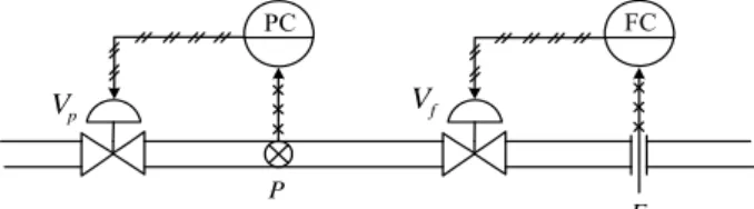
Additionally, there can be interference in mutual outputs, as shown in Figure 1. Here, when the pressure ( ) is controlled by operating the pressure control valve (
), the flow ( ) within the pipe changes at the same time. When the flow is controlled by operating the flow control valve (
), the flow within the pipe changes along with the pressure. That is, un- der the condition that the flow is consistent with a target value while the pressure differs from a target value, when is operated to adjust the pressure, the flow—which has the correct value—is inevitably changed. A similar situation oc- curs for the pressure when is operated to adjust the flow.
PC FC
P
F
V
pV
fFigure 1: Flow and pressure control system
2.2 TITO System
In this paper, a TITO system, which is one of the most com- mon multivariable systems, is examined. As shown in Figure 2, a TITO system comprises two inputs and two outputs.
PID Controller 2
PID Controller 1
+ -
+ -
+ +
+ +
)
11
( s G
)
22
( s ) G
2
( s U
)
1
( s U
(s) Y
2(s) Y
1(s) E
2(s) R
2(s) E
1(s) R
1)
12
( s G
)
21
( s G
Figure 2: Block diagram of a TITO system As shown in the figure, the TITO system is divided into the transfer functions
,
,
, and
; and
and
induce mutual interference in their outputs.
∈
is the reference input, ∈
is the error,
∈
is the control input, and ∈
is the output vector.
The transfer function matrix of this TITO system is expressed by Equation (1).
(1)
As shown in Figure 2, each control input is determined by the PID controller using each error variable. This can be ex- pressed in a diagonal matrix PID controller format excluding the transfer matrix, as shown in Equation (2).
(2)
and
represent the con- trollers PID1 and PID2, respectively.
To obtain each gain matrix, Equation (2) can be modified into Equation (3).
·
·
(3)
where
∈
×is the proportional gain matrix,
∈
×is the integral gain matrix, and
∈
×is the derivative gain matrix. They can be expressed as follows.
(4)
3. PID Controller of the TITO System 3.1 PID controller based on Z-N
In the TITO system, the outputs of the two controllers have a mutual effect on each other; thus, the tuning rule of Z-N can not be directly applied to a single-input single-output (SISO) system. Thus, it is necessary to divide a TITO system into two SISO systems. When the control input
in Figure 2 is set as ‘0’ in order to design a PID1 controller, it can be divided into two SISO systems for the input
, as shown in Figure 3. In this regard, one SISO system becomes a closed-loop system, as shown in Figure 3 (a), and the other becomes an open-loop system, as shown in Figure 3 (b).
In Figure 3 (b), the input
can be considered as a
disturbance or sensor noise added to the output
, and
this does not affect the error
necessary for the con-
troller design. Thus, to design a PID1 controller for the ref-
erence input
, only Figure 3 (a) must be considered.
On the other hand, to design a PID2 controller, the control variable
must be removed. Then, the system in Figure 2 can be divided into two SISO systems for the input
, similarly to Figure 3. Here, one SISO system be- comes a closed-loop system, and the other becomes an open-loop system.
The Z-N tuning formulas for the PI and PID controllers are shown in Table 1. We considered only the PID controller.
+
-
K s U
1( s ) G
11( s ) Y
1( s ) s
K
p1 K
i1
d1)
1
( s ) E
1
( s R
(a) Closed loop system
)
21 ( s
) G
1
( s
U Y
2( s )
s s K K
p1 K
i1
d1)
1
( s R
(b) Open loop system
Figure 3: Decoupled TITO system(
=0)
Table 1: Ziegler-Nichols tuning rules
Controller PID controller parameters
PI 0.45
0.8
-
PID 0.6
0.5
0.125
3.2 PID controller based on RCGA 3.2.1 Structure and operator of RCGA
In this section, an RCGA used to resolve an optimization problem that occurs during the design of PID controllers is briefly examined [7].
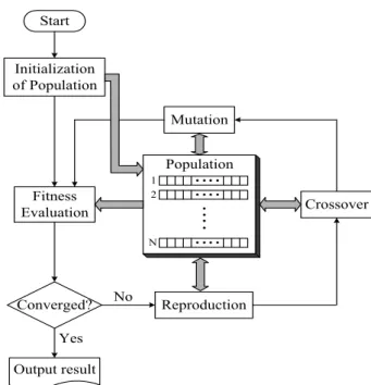
An RCGA is an algorithm based on natural selection and genetics. It starts from an initial group that consists of a number of individuals (chromosomes) and a group that has been newly formed through fitness evaluation. A genetic op- erator repeatedly performs simulated evolution until an opti- mal solution is found. Figure 4 shows the operation process of the RCGA employed in this paper.
For the genetic operator used in the RCGA, reproduction similar to the gradient, a modified simple crossover, and dy- namic mutation are used. A scaling-window method is used to increase the selection pressure, and an elite strategy is used to guarantee that the strongest individual is passed onto the next generation by preventing the optimal individual ex- tinction of a generation.
Start
Initialization of Population
Fitness Evaluation
Output result
Crossover
Reproduction Mutation Population
Yes No
1 2
N
Converged?
Figure 4: Basic structure of RCGA adopted
3.2.2 Optimal tuning of a PID controller based on RCGA Regarding the objective function necessary to determine the PID V controller parameters according to the RCGA, three kinds of objective functions are applied, as previously mentioned.
The objective functions used to determine the parameters of the PID controller are the ISE (Integral of squared error) shown in Equation (5), which can obtain a global solution even in a search environment with multi-modal characteristics and can easily obtain a derivative; the IAE (Integral of abso- lute error) shown in Equation (6); and the ITAE (Integral of time-absolute error) shown in Equation (7).
ISE
∞
(5)
IAE
∞ (6)
ITAE
∞ (7)
The ISE is frequently used for optimally designing con-
trollers owing to its ease of interpretation but gives a large
offset when the error is large and a small offset when the er-
ror is small. Thus, it is insensitive to the change in the co-
efficient near an optimal solution. On the other hand, the
IAE assigns an equal offset for the positive or negative error
by considering the absolute magnitude of the error and has
better sensitivity than the ISE. The ITAE is a very useful
criterion that gives an offset for a long-term transient
phenomenon. It has far more discriminating power than the IAE and ISE, and the minimum value of this integral can be better defined when the parameters of the system change [8].
4. Simulation 4.1 System and controller design
To examine the validity of the proposed method, a line- arized TITO system [1] is considered, as shown in Equation (8). This system is not a typical process-control problem, as the plant is not diagonally dominant and also has one large and negative diagonal gain.
(8)
When the closed-loop transfer function is obtained by set- ting the critical proportional gain
for
, it is ex- pressed by Equation (9).
(9)
The
value of the stability limit where an output in- duces oscillation with a constant amplitude can be obtained by the Routh–Hurwitz stability criterion.
In this case, the value is
. When the period of os- cillation
is calculated by determining the oscillation fre- quency using the characteristic equation in Equation (9), it is 0.56 sec. Therefore, the parameters of the PID controller ac- cording to the Z-N tuning rule (refer to Table 1) are de- termined as follows:
,
and
.
For the control variables of the RCGA, the population size
, reproduction coefficient , crossover probability
, and mutation probability
are used. The upper boundary values of the PID controller parameters
,
, and
are set to 25, including a sufficient margin based on the PID controller parameters obtained by the Z-N method. By decreasing the search range of RCGA, the compu- tation time is reduced, and a global solution is guaranteed.
The parameters of the PID controller are determined by using the ISE, IAE, and ITAE as objective functions of the RCGA. Figures 5–7 show the determination of the PID con-
troller parameters by using the ISE, IAE, and ITAE.
J
ISE
tf
(10) J
IAE
tf
(11)
J
I TAE
tft· e
t t· e
t dt (12)
where
is a time that is sufficiently large that the integral after this time can be ignored.
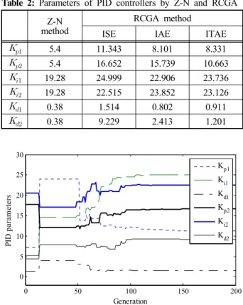
Table 2 summarizes the PID controller parameters based on Z-N and the RCGA.
Table 2: Parameters of PID controllers by Z-N and RCGA method Z-N
RCGA method
ISE IAE ITAE
5.4 11.343 8.101 8.331
5.4 16.652 15.739 10.663
19.28 24.999 22.906 23.736
19.28 22.515 23.852 23.126
0.38 1.514 0.802 0.911
0.38 9.229 2.413 1.201
0 50 100 150 200
0 5 10 15 20 25 30
Generation
PI D p ara m et ers
K
p1K
i1K
d1K
p2K
i2K
d2Figure 5: Tuning process of PID parameter using ISE
0 50 100 150 200
0 5 10 15 20 25 30
Generation
PI D p ara m et ers
Kp1 Ki1 Kd1 Kp2 Ki2 Kd2
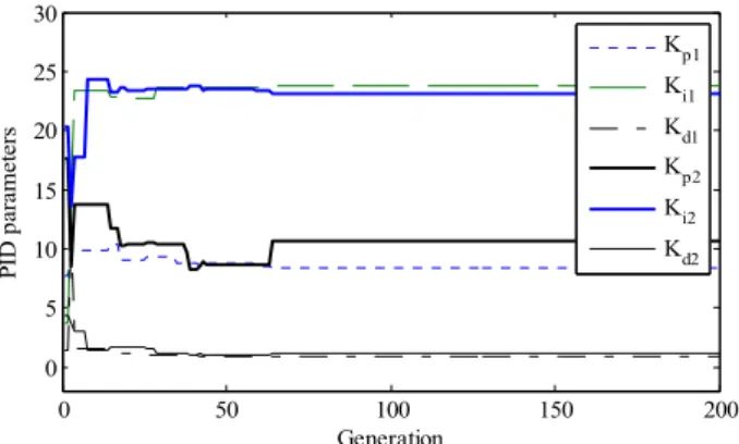
Figure 6: Tuning process of PID parameter using IAE
0 50 100 150 200 0
5 10 15 20 25 30
Generation
PID parameters
Kp1 Ki1 Kd1 Kp2 Ki2 Kd2