Ⅰ. INTRODUCTION
In the field of dental prosthetics, advances in digital dentistry have resulted in not only new materials, but also new fabrication methods. Traditionally, metal prostheses were produced by casting methods, but in recent times, computer-aided design and computer-aided production methods are being proposed. Commonly used casting methods involve complex production steps and have the disadvantage of using mostly wax patterns that can deform easily, and as such, CAD/CAM methods are being
considered as an alternative that can overcome this problem (Abduo et al., 2010; V et al., 2014; Zeltser et al., 1985).
CAD/CAM can be divided largely into subtractive technique or additive technique, depending on the process involved. Currently subtractive manufacturing, or milling, which is widely used, is advancing at a rapid pace (Fasbinder, 2006). The milling process is often used to fabricate zirconia prostheses that are difficult to produce by casting and recent introduction of milling alloys has widened the range of materials available.
Additive manufacturing, meaning 3D printing, is a recently introduced method that uses digital images to add layers for manufacturing (Huang et al., 2015). A wide variety of materials can be used, and metal prostheses can
대한치과재료학회지 43(1) : 101-110, 2016ISSN:2384-4434 (Print); 2384-3268 (Online) Available online at http://www.kadm.org http://dx.doi.org/10.14815/kjdm.2016.43.1.101
제작 방법에 따른 금속과 지르코니아 코핑의 변연 및 내면 적합도
정지혜*
원광대학교 치과대학 치과보철학교실
<Abstract>
Marginal and internal fit of metal and zirconia copings depending on manufacturing methods
Ji-Hye Jung
*Department of Prosthodontics, School of Dentistry, Wonkwang University
본 연구는 주조용 코발트-크롬 합금 코핑 (CC), 밀링용 코발트-크롬 합금 코핑 (CM), 밀링용 지르코니아 코핑 (ZM), 3D 프린팅용 코발트-크 롬 합금 코핑 (CP)의 변연 및 내면 적합도를 측정하고자 각각 10개의 코핑을 제작하였다. 저점도 실리콘 인상재를 이용하여 리플리카 시편을 제작하고 협설과 근원심으로 잘라서 각각의 시편에서 16군데를 현미경을 이용하여 200배의 비율로 측정하였다. 측정값은 One-way ANOVA 를 이용해서 통계처리하였으며 Scheffe 사후 검정을 시행하였다. 실험의 한계내에서 CC 그룹의 변연 및 내면간극은 CM, ZM, CP 그룹에 비해 유의하게 작았다 (p<.05). 그러나 CAD/CAM을 이용하여 제작한 CM, ZM, CP 그룹 또한 우수한 변연 및 내면 적합도를 보였다.
Key words
: CAD/CAM, Internal Fit, Marginal Fit, Metal Coping, Zirconia Coping* Correspondence: 정지혜 (ORCID ID: 0000-0003-3322-4011) (우 54538) 전라북도 익산시 익산대로 460 원광대학교 치과대학 치과보철학교실
Tel: +82-63-859-2938, Fax: +82-63-857-4002 E-mail: stop-it@hanmail.net
be fabricated via direct metal laser sintering, one of the 3D printing methods, which selectively sinters metal powders with a laser. By using this method, defects and twisting that were problematic in conventional casting methods can be prevented (Ebert et al., 2009; Miyazaki et al., 2009), while complex structures that could not be made by milling can also be fabricated (Kanazawa et al., 2014).
The fitness of fixed prostheses, along with strength and color stability, has been the topic of many studies on important conditions of prostheses. Evaluation of the fitness of fixed prosthesis is divided into marginal fit and internal fit where poor fitness in fixed prostheses can cause gingival inflammation and result in secondary caries owing to cement dissolution (Abduo et al., 2010; Boening et al., 2000).
Thus far, there have been many studies on the difference in fitness according to the fabrication methods for metal crowns, difference in fitness of ceramic prosthesis according to the fabrication methods, and comparison of fitness between different types of zirconia restorations.
However, virtually no studies have compared the fitness of zirconia copings together with metal copings according to the fabrication methods. Accordingly, the present study compared the marginal and internal fit of metal copings fabricated by the traditional casting process, metal copings fabricated by the milling process, zirconia copings fabricated by the milling process, and metal copings fabricated by 3D printing for the purpose of examining their differences and characteristics.
Ⅱ. MATERIALS AND METHODS
For fitness comparison, casting Co-Cr alloy (StarLoy C, DeguDent, Germany), milling Co-Cr alloy (Ceramill Sintron, Amanngirrbach, Germany), milling zirconia (Ceramill Zi, Amanngirrbach, Germany), and 3D-printing Co-Cr alloy
(EOS CobaltChrome SP2; EOS GmbH, Krailling, Germany) were used to fabricate a total of 40 copings, with 10 for each process (Table 1).
1. Fabrication of the metal abutment model
For the experiment, an abutment was formed by preparing a resin tooth (LHW-1, M.tech, Korea) in the form of a maxillary left second premolar. The occlusal surface was reduced by 2 mm and a chamfer margin of 1 mm was given, while a milling machine (S3-Master Milling Unit, Schick Dental, Germany) was used to give the axial plane an inclination of 6°. The surface of the formed resin tooth was given a smooth finish, after which it was invested for casting with Ni-Cr alloy (Remanium CS, Dentaurum, Germany).
2. Scanning of the metal abutment model
For fabrication of copings using CAD/CAM, powder (Ceramill scanmaker, Amanngirrbach, Germany) was applied to the abutment model and the model was scanned using a model scanner (Ceramill map 400, Amanngirrbach, Germany).
3. Fabrication of the stone model
Polyvinyl siloxane (Aquasil LV, Dentsply, USA) and putty impression materials (Exafine putty type, GC America Inc., USA) were applied to the abutment model to produce the mold for fabrication of the stone model. A total of 20 stone models were fabricated by vacuum mixing type IV high strength dental stone (Snowrock, DK Mungyo, Korea) in the mold, according to the ratio indicated by the manufacturer.
4. Fabrication of copings
A total of 10 copings with a thickness of 0.5 mm were
fabricated for each group.
1) Casting Co-Cr alloy coping (CC)
In the stone model of the metal abutment, the die spacer (YETI, GmbH, Germany) was applied three times up to upward margin of 0.5 mm, being very careful to have it evenly spaced as much as possible by 20 μm (Cho et al., 2006). A single technician produced all ten wax patterns.
After fabricating the metal coping and adjusting the thickness to 0.5 mm, an index was produced. The wax patterns were carefully produced using this index as the reference. The wax patterns were invested and cast with Co-Cr alloy (StarLoy C, DeguDent, Germany).
2) Milling Co-Cr alloy coping (CM)
The copings were designed from scanned files using a dedicated program (Ceramill mind, Amanngirrbach, Germany). Thickness of the copings was 0.5 mm, while 20 μm was given at 0.5 mm upwards from the margin for the cement space. This was saved in the STL file format.
Using the STL file, Co-Cr alloy block (Ceramill Sintron, Amanngirrbach, Germany) was milled using a milling machine (Ceramill Motion2, Amanngirrbach, Germany).
Temperature inside programmed Sintron sintering furnace (Ceramill argotherm 2, Amanngirrbach, Germany) was
raised up to 1280℃ and the temperature was maintained for 1 hour. Then, the coping was completed after annealing.
3) Milling zirconia coping (ZM)
The saved STL file was used to mill the zirconia block (Ceramill Zi, Amanngirrbach, Germany) with a milling machine (Ceramill Motion2, Amanngirrbach, Germany). In accordance with the product instructions, temperature of the sintering furnace (Ceramill therm, Amanngirrbach, Germany) was raised from 20℃ to 1450℃ and coping was produced by sintering, while maintaining the temperature at 1450℃ for 2 hours.
4) 3D printing Co-Cr alloy coping (CP)
Using the saved STL file, Co-Cr powder (EOS CobaltChrome SP2; EOS GmbH, Krailling, Germany) was produced by DMLS machine (EOSINT M270; EOS GmbH, Krailling, Germany). The powder was layered while being sintered with a thickness of 20 μm under nitrogen gas environment. After sintering was completed, annealing was performed, according to the instructions of the manufacturer, for stress release.
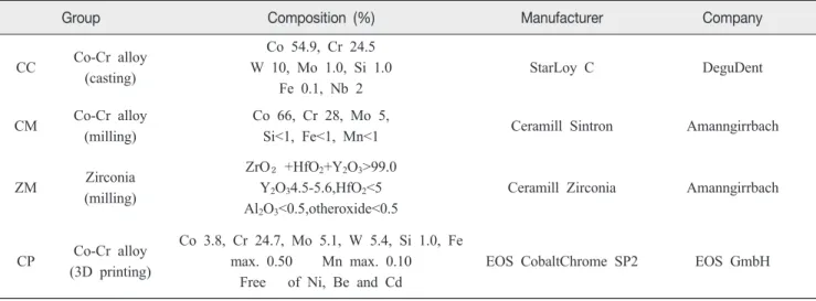
Table 1.
Materials used in this study
Group Composition (%) Manufacturer Company
CC Co-Cr alloy (casting)
Co 54.9, Cr 24.5 W 10, Mo 1.0, Si 1.0
Fe 0.1, Nb 2
StarLoy C DeguDent
CM Co-Cr alloy (milling)
Co 66, Cr 28, Mo 5,
Si<1, Fe<1, Mn<1 Ceramill Sintron Amanngirrbach
ZM Zirconia
(milling)
ZrO₂+HfO2+Y2O3>99.0 Y2O34.5-5.6,HfO2<5 Al2O3<0.5,otheroxide<0.5
Ceramill Zirconia Amanngirrbach
CP Co-Cr alloy (3D printing)
Co 3.8, Cr 24.7, Mo 5.1, W 5.4, Si 1.0, Fe max. 0.50 Mn max. 0.10
Free of Ni, Be and Cd
EOS CobaltChrome SP2 EOS GmbH
5. Fitness measurement
1) Replica fabrication
Silicone replica method was used to measure the marginal and internal fit. First, the inside of the fabricated metal coping was filled with light body silicone impression (Examixfine injection type, GC America Inc., USA) and positioned on the metal model. Then, 50 N was applied in a static loading device and hardened for 5 minutes. The coping was carefully separated, and to fix the impression material that shows the inner gaps, regular body silicone impression material (Examixfine regular type, GC America Inc., USA) was applied from the outside and hardened. Finally, cutting was performed on the mesiodistal and buccopalatal sides using a blade (Kiato plus, Adityadispomed, India).
2) Fitness measurement
Measurement areas were designated according to the method suggested by Holmes et al. (Holmes et al., 1989) and 8 points from each direction were observed with a stereo microscope (JTZ-7XT, Samwon, Korea) at ×200 magnification. Using a digital camera (Digital sight DS-5M, Nikon, Japan) and analysis (Digital sight DS-L1, Nikon,
Japan), the thickness of the orange colored area, which was the Examixfine injection type silicone area (Examixfine injection type, GC America Inc., USA), was measured vertically. A total of 16 points were divided into the marginal gap, cervical gap, axial gap, and occlusal gap (Figure 1).
6. Statistics
Reference point data were recorded from each group, and means and SDs were also recorded. 1-way ANOVA was used to analyze inter-group differences based on position and intra-group differences based on the position, after which, significant inter-group differences were evaluated using the Scheffe test. All statistical analyses were performed using SPSS ver. 21.0 (IBM SPSS Statistics, IBM, USA) and statistical differences were evaluated at confidence intervals of 95%.
Ⅲ. RESULTS
1. Inter-group differences based on measurement area
1) Marginal fit (MG - 1, 8, 9, 16 point)
In the CC group, mean fitness was found to be 9.15±4.32 μm, which was significantly smaller than that of the CM (15.91±2.46 ㎛), ZM (16.67±2.25 ㎛) and CP (15.85±2.32
㎛) groups, while these three groups did not show any significant differences amongst each other (Figure 2).
2) Internal fit
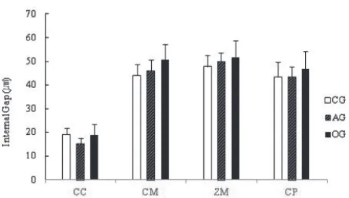
(1) Cervical fit (CG - 2, 7, 10, 15 point)
In the CC group, mean cervical gap was found to be 19.15±6.27 μm, which was significantly smaller than that of the CM (44.18±4.39 ㎛), ZM (47.92±7.48 ㎛), and CP (43.47±4.76 ㎛) groups. The ZM group showed a value
Figure 1. Schematic diagram of the measuring points.a) buccopalatal section: 1,8=marginal gap (MG), 2,7=cervical gap (CG), 3,6=axial gap (AG), 4,5=occlusal gap (OG).
b) mesiodistal section: 9,16=marginal gap (MG), 10,15=
cervical gap (CG), 11,14=axial gap (AG), 12,13=occlusal gap
(OG).
that was significantly larger than that of the CM and CP groups, while no significant difference was observed between the CM and CP groups (Figure 3).
(2) Axial fit (AG - 3, 6, 11, 14 point )
In the CC group, mean axial gap was found to be 15.26±7.23 μm, which was significantly smaller than that of the CM (46.01±4.68 ㎛), ZM (50.06±8.50 ㎛), and CP (43.61±3.60 ㎛) groups. The ZM group showed a value that was significantly larger than that of the CM and CP groups, while no significant difference was observed between the CM and CP groups (Figure 3).
(3) Occlusal fit (OG - 4, 5, 12, 13 point)
In the CC group, mean occlusal gap was found to be 18.90±7.14 μm, which was significantly smaller than that of the CM (50.72±6.31 ㎛), ZM (50.06±8.50 ㎛), and CP (43.61±3.60 ㎛) groups. The ZM group showed a value that was significantly larger than that of the CP groups, but did not significantly differ from that of the CM group.
Moreover, no significant difference was observed between the CM and CP groups (Figure 3).
2. Intra-group difference
1) Fitness in the CC group
The marginal gap was found to be 9.15±4.32 μm, which was significantly smaller than the other positions, the CG (19.15±6.27 ㎛), AG (15.26±7.23 ㎛), and OG (18.90±7.14 ㎛) groups. The remaining three groups did not show any significant differences amongst each other (Table 2).
2) Fitness in the CM group
The marginal gap was found to be 15.91±2.46 μm, which was significantly smaller than the other positions, the CG, AG, OG groups. The OG group showed a value that was significantly larger than that of the CG and AG groups, but no significant difference was found between the CG and AG groups (Table 2).
3) Fitness in the ZM group
The marginal gap was found to be 16.15±2.25 μm, which was significantly smaller than the other positions, the CG, AG, OG groups. The remaining three groups did not show significant differences amongst each other (Table 2).
Figure 2. Mean and SD of marginal gap in the four experimental groups. CC, Casting Co-Cr copings; CM, Milling Co-Cr copings;
ZM, Milling zirconia copings; CP, 3D printing Co-Cr copings.
* p<.05 by Scheffe test for multiple comparison.
Figure 3. Mean and SD of internal gaps in the four experimental groups. CC, Casting Co-Cr copings; CM, Milling Co-Cr copings;
ZM, Milling zirconia copings; CP, 3D printing Co-Cr copings.
CG, cervical gap; AG, axial gap; OG, occlusal gap.
4) Fitness in the CP group
The marginal gap was found to be 15.85±2.32 μm, which was significantly smaller than the other positions, the CG, AG, OG groups. The OG group showed a value that was significantly larger than that of the CG and AG group, while no significant difference was found between the CG and AG groups (Table 2).
Ⅳ. DISCUSSION
In the present study, the marginal and internal fit of zirconia copings and Co-Cr alloy copings fabricated by the casting, milling, and 3D printing methods were measured and compared with the replica technique.
There are no standardized methods for measuring the fitness of prostheses (Habib et al., 2014). Methods for measuring marginal and internal fit that have been used since a long time include direct observations, measurement of cut specimens, and use of replicas; the use of x-ray microtomography (micro-CT) and the use of replicas in digital applications have been introduced recently (Gavelis et al., 2004; Kim et al., 2014; Pimenta et al., 2015). The replica method is advantageous, as it is reliable, non- invasive, and usable in clinical trials; moreover, it allows
repeated measurements (Martins et al., 2012). Rahme et al.
(Rahme et al., 2008) reported that the replica technique showed virtually no difference versus measurements for directly cutting the specimen. Moreover, a study by Molin and Karlsson (Molin and Karlsson, 1993) also showed that the measured values were very consistent when measurements were taken repeatedly. Furthermore, Laurent M et al. (Laurent et al., 2008) stated that the appropriate use of replicas serves as an efficient method for taking measurements from any position.
Clinically, there is no clearly defined criterion on how much marginal gap is allowable. In theory, space needed for the cement is 20~40 μm, but it is difficult to actually achieve this goal (Gardner, 1982). The criterion that is referenced in many recent studies is derived from the study by Mclean and von Fraunhofer. After studying 1,000 crowns, they reported a maximum allowable marginal gap of 120 μm and indicated that a marginal gap less than 80 μm was difficult to find out clinically (McLean and von Fraunhofer, 1971). Additionally, there is no standardized criterion for internal fit. However, Holmes et al. (Holmes et al., 1989) obtained separate measurements from the axial gap , cervical gap, and occlusal gap, and the present study also followed this method.
In the present study, the marginal gap of casting alloy
Table 2.Mean value and SD of gap according to four different locations(㎛)
* Different letters in the same row show significant differences (p<.05)
CC, Casting Co-Cr copings; CM, Milling Co-Cr copings; ZM, Milling zirconia copings; CP, 3D printing Co-Cr copings.
MG,marginal gap; CG,cervical gap; AG, axial gap; OG, occlusal gap.
Group MG (㎛) CG (㎛) AG (㎛) OG (㎛)
CC 9.15 (4.32a*) 19.15±6.27b) 15.26 (7.23b) 18.90 (7.14b)
CM 15.91 (2.46a) 44.18 (4.39b) 46.01 (4.68b) 50.72 (6.31c)
ZM 16.15 (2.25a) 47.92 (7.48b) 50.06 (8.50b) 51.47 (7.30b)
CP 15.85 (2.32a) 43.47 (4.76b) 43.61 (3.60b) 46.90 (4.10c)
coping was 9.15±4.32 μm, while all other groups showed values in the range of 15~16 μm. This finding was consistent with those of previous studies that showed that casting alloy copings had better fitness than those made by the CAD/CAM method (Bayramoglu et al., 2015; Martins et al., 2012; Vojdani et al., 2013). Gaps may appear in castings owing to deformation of the wax pattern, expansion by the investment material, and shrinkage in the alloy during casting (McMillan and Darvell, 2000). The skill level of the technician may also have a significant effect on fitness due to the nature of the fabrication process. Hence, previous studies on casting alloy prostheses showed a wide ranging marginal gap of 34-170 μm (Pimenta et al., 2015; Xu et al., 2014). It is believed that the present study showed very good marginal fit because casting alloy prostheses were made by an experienced technician and fit without adjust.
When fabricating prostheses by the milling process, factors that can influence fitness are retentive groove of the abutment, angle, scan method, software design, machining, and shrinkage effect (Pimenta et al., 2015). In various studies, prostheses fabricated by the milling process showed similar fitness to prostheses cast with non-precious metal alloys (Colpani et al., 2013; Reich et al., 2005). However, in other studies, prostheses fabricated by digital methods showed significantly better fitness than those fabricated by casting methods (Colpani et al., 2013; Kim et al., 2014; Park et al., 2015; V et al., 2014). In contrast, larger gaps were noted in both marginal and internal fit from milling process and 3D printing than from casting method in the present study. However, although the casting alloy copings showed significantly small gaps, the group that used CAD/CAM also showed clinically allowable marginal gap of < 20 μm.
Moreover, despite showing a larger mean value than casting alloy copings, the groups that used CAD/CAM showed small, consistent SD values; thus, they can be considered to have higher precision than casting copings.
The milling process is a method that was used primarily for machining zirconia. Because this process uses commercially available blocks, it had the advantage of using a material that has uniform structure, but it was difficult to mill a hard material. Therefore, to manufacture metal, large and expensive equipment needed to be used, i.e., a milling center had to be used. However, with the recent development of pre-sintered metal, milling metal has become much easier (Stawarczyk et al., 2014). Sintron used in the present study was millable Co-Cr alloy with a milling machine. After milling, sintering for 5 hours and 30 minutes under argon gas, according to a pre-set program, results in 11% shrinkage in volume, and the mechanical strength becomes similar to that of casting Co-Cr alloy (Suleiman and Vult von Steyern, 2013). Many studies has been conducted on Co-Cr alloy for milling use, and according to the study (Park et al., 2015) milling Co-Cr alloy showed better fitness than casting Co-Cr alloy copings, while Kim et al. (Kim et al., 2014) reported that marginal fit of milling Co-Cr alloy was better than casting and 3D printing Co-Cr alloy copings.
In many studies, comparison of internal fit between zirconia copings and metal copings showed zirconia copings to have larger axial wall gap than metal copings (Aktas et al., 2014; Vojdani et al., 2013). With respect to such differences, Beuer et al. (Beuer et al., 2008) indicated that the sintering process, along with scan, data collection, milling calculation, and actual milling process, can influence the accuracy of prostheses. Similar to the casting method, this method is also said to be affected by the skill level of the technician who operates the equipment (Pimenta et al., 2015; Tamim et al., 2014).
Direct metal laser sintering (DMLS), which uses Co-Cr
powder, is one of the most widely used 3D printing
methods in dentistry (Tinschert et al., 2001). This method
uses a laser beam to focus high energy on metal powder
to fuse a thin layer on a specific area, and it is capable
of producing a 3D shape directly from a CAD model. This
can be considered as a new technology that can replace casting of non-precious metals (V et al., 2014). In comparison to milling, 3D printing is a more recent fabrication method, and is the subject of various evaluations currently. Recent studies have reported fabrication of complex metal structures of removable dentures (Kanazawa et al., 2014) and complete dentures (Sachs et al., 2014) with relatively satisfactory fitness. Reich S et al. (Reich et al., 2005) reported marginal fit of 3-unit dental bridge fabricated by the DMLS method was very satisfactory. Moreover, in the study (Kim et al., 2014) metal copings fabricated by the DMLS method showed significantly better fitness than copings produced by the casting or milling processes. In the present study, metal copings fabricated using the DMLS showed clinically satisfactory marginal and internal gaps.
Since mean and SD values for fitness were similar to those of the traditional milling method, it is believed that fabrication of fixed prosthesis with consistency is possible.
The present study had few limitations. All copings were fabricated under ideal conditions, and hence, they cannot represent clinical situations. However, the objective of the present study was to compare the fabrication methods without any extraneous factors. Future studies must evaluate fitness in more complex prostheses.
Ⅴ. CONCLUSION
The mean marginal and internal fit of the casting Co-Cr alloy coping group were significantly better than other three groups. In all groups marginal gaps were smaller than internal gaps. Despite showing a larger mean value than casting alloy copings, the groups that used CAD/CAM showed good mean value and small, consistent SD values.
Thus they can be also expected to show clinically satisfactory fitness.
Ⅵ. REFERENCES
Abduo J, Lyons K, Swain M (2010). Fit of zirconia fixed partial denture: a systematic review.
J Oral Rehabil37(11)
:866-876.
Aktas G, Ozcan N, Aydin DH, Sahin E, Akca K (2014). Effect of digitizing techniques on the fit of implant-retained crowns with different antirotational abutment features.
J Prosthet Dent
111(5)
:367-372.
Bayramoglu E, Kulak Ozkan Y, Yildiz C (2015). Comparison of marginal and internal fit of press-on-metal and conventional ceramic systems for three- and four-unit implant-supported partial fixed dental prostheses: An in vitro study.
J Prosthet Dent114(1)
:52-58.
Beuer F, Schweiger J, Edelhoff D (2008). Digital dentistry:
an overview of recent developments for CAD/CAM generated restorations.
Br Dent J204(9)
:505-511.
Boening KW, Wolf BH, Schmidt AE, Kastner K, Walter MH (2000). Clinical fit of Procera AllCeram crowns.
J Prosthet Dent84(4)
:419-424.
Cho SH, Chang WG, Lim BS, Lee YK (2006). Effect of die spacer thickness on shear bond strength of porcelain laminate veneers.
J Prosthet Dent95(3)
:201-208.
Colpani JT, Borba M, Della Bona A (2013). Evaluation of marginal and internal fit of ceramic crown copings.
Dent Mater29(2)
:174-180.
Ebert J, Ozkol E, Zeichner A, Uibel K, Weiss O, Koops U
et al.(2009). Direct inkjet printing of dental prostheses made of zirconia.
J Dent Res88(7)
:673-676.
Fasbinder DJ (2006). Clinical performance of chairside CAD/CAM restorations.
J Am Dent Assoc137 Suppl (22s-31s.
Gardner FM (1982). Margins of complete crowns--literature review.
J Prosthet Dent48(4)
:396-400.
Gavelis JR, Morency JD, Riley ED, Sozio RB (2004). The
effect of various finish line preparations on the marginal
seal and occlusal seat of full crown preparations. 1981.
J Prosthet Dent
92(1)
:1-7.
Habib SR, Asiri W, Hefne MJ (2014). Effect of anatomic, semi-anatomic and non-anatomic occlusal surface tooth preparations on the adaptation of zirconia copings.
J Adv Prosthodont6(6)
:444-450.
Holmes JR, Bayne SC, Holland GA, Sulik WD (1989).
Considerations in measurement of marginal fit.
J Prosthet Dent62(4)
:405-408.
Huang Z, Zhang L, Zhu J, Zhao Y, Zhang X (2015). Clinical Marginal and Internal Fit of Crowns Fabricated Using Different CAD/CAM Technologies.
J Prosthodont24(4)
:291-295.
Kanazawa M, Iwaki M, Minakuchi S, Nomura N (2014).
Fabrication of titanium alloy frameworks for complete dentures by selective laser melting.
J Prosthet Dent112(6)
:1441-1447.
Kim KB, Kim JH, Kim WC, Kim JH (2014). Three- dimensional evaluation of gaps associated with fixed dental prostheses fabricated with new technologies.
J Prosthet Dent112(6)
:1432-1436.
Laurent M, Scheer P, Dejou J, Laborde G (2008). Clinical evaluation of the marginal fit of cast crowns--validation of the silicone replica method.
J Oral Rehabil35(2)
:116-122.
Martins LM, Lorenzoni FC, Melo AO, Silva LM, Oliveira JL, Oliveira PC
et al.(2012). Internal fit of two all-ceramic systems and metal-ceramic crowns.
J Appl Oral Sci20(2)
:235-240.
McLean JW, von Fraunhofer JA (1971). The estimation of cement film thickness by an in vivo technique.
Br Dent J131(3)
:107-111.
McMillan LC, Darvell BW (2000). Rheology of dental waxes.
Dent Mater
16(5)
:337-350.
Miyazaki T, Hotta Y, Kunii J, Kuriyama S, Tamaki Y (2009).
A review of dental CAD/CAM: current status and future perspectives from 20 years of experience.
Dent Mater J28(1)
:44-56.
Molin M, Karlsson S (1993). The fit of gold inlays and three ceramic inlay systems. A clinical and in vitro study.
Acta Odontol Scand51(4)
:201-206.
Park JK, Lee WS, Kim HY (2015). Accuracy evaluation of metal copings fabricated by computer-aided milling and direct metal laser sintering systems. 7(2)
:122-128.
Pimenta MA, Frasca LC, Lopes R, Rivaldo E (2015).
Evaluation of marginal and internal fit of ceramic and metallic crown copings using x-ray microtomography (micro-CT) technology.
J Prosthet Dent114(2)
:223-228.
Rahme HY, Tehini GE, Adib SM, Ardo AS, Rifai KT (2008).
In vitro evaluation of the "replica technique" in the measurement of the fit of Procera crowns.
J Contemp Dent Pract9(2)
:25-32.
Reich S, Wichmann M, Nkenke E, Proeschel P (2005).
Clinical fit of all-ceramic three-unit fixed partial dentures, generated with three different CAD/CAM systems.
Eur J Oral Sci113(2)
:174-179.
Sachs C, Groesser J, Stadelmann M, Schweiger J, Erdelt K, Beuer F (2014). Full-arch prostheses from translucent zirconia: accuracy of fit.
Dent Mater30(8)
:817-823.
Stawarczyk B, Eichberger M, Hoffmann R, Noack F, Schweiger J, Edelhoff D
et al.(2014). A novel CAD/CAM base metal compared to conventional CoCrMo alloys:
an in-vitro study of the long-term metal-ceramic bond strength.
Oral Health Dent Manag13(2)
:446-452.
Suleiman SH, Vult von Steyern P (2013). Fracture strength of porcelain fused to metal crowns made of cast, milled or laser-sintered cobalt-chromium.
Acta Odontol Scand71(5)
:1280-1289.
Tamim H, Skjerven H, Ekfeldt A, Ronold HJ (2014). Clinical evaluation of CAD/CAM metal-ceramic posterior crowns fabricated from intraoral digital impressions.
Int J Prosthodont27(4)
:331-337.
Tinschert J, Natt G, Mautsch W, Spiekermann H, Anusavice
KJ (2001). Marginal fit of alumina-and zirconia-based
fixed partial dentures produced by a CAD/CAM system.
Oper Dent
26(4)
:367-374.
V H, Ali SAM, N J, Ifthikar M, Senthil S, Basak D
et al.(2014). Evaluation of internal and marginal fit of two metal ceramic system - in vitro study.
J Clin Diagn Res8(12)
:Zc53-56.
Vojdani M, Torabi K, Farjood E, Khaledi A (2013).
Comparison the Marginal and Internal Fit of Metal Copings Cast from Wax Patterns Fabricated by CAD/
CAM and Conventional Wax up Techniques.
J Dent (Shiraz)14(3)
:118-129.
Xu D, Xiang N, Wei B (2014). The marginal fit of selective laser melting-fabricated metal crowns: an in vitro study.
J Prosthet Dent