http://dx.doi.org/10.7734/COSEIK.2016.29.1.61 Engineering Institute of Korea
유한요소법을 이용한 복합재의 물성치 도출에 대한 연구
정 철 균1․김 성 욱1†
1한국과학기술원 기계공학과
Study on Material Properties of Composite Materials using Finite Element Method
Chul-Gyun Jung1 and Sung-Uk Kim1†
1Division of Mechanical Engineering, KAIST., Daejeon, 34141, Korea
Abstract
Composites are materials that are widely used in industries such as automobile and aircraft. The composite material is required as a material for using in a high temperature environment as well as acting as a high pressure environment like the nozzle part of the ship. It is important to know the properties of composites. Result values obtained substituting the properties of matrix and fiber numerically have an large error compared with experimental value. In this study we utilize CASADsolver EDISON program for using Finite Element Method. Properties by substituting the fiber and Matrix properties of the composite material properties were compared with those measured in the experiment and calculated by the empirical properties.
Keywords : material property, composite material, matrix, fiber, finite element method
†Corresponding author:
Tel: +82-42-826-6030; E-mail: rltjdn@kaist.ac.kr Received May 18 2015; Revised June 2 2015;
Accepted November 9 2015
Ⓒ 2016 by Computational Structural Engineering Institute of Korea
This is an Open-Access article distributed under the terms of the Creative Commons Attribution Non-Commercial License(http://creativecommons.
org/licenses/by-nc/3.0) which permits unrestricted non-commercial use, distribution, and reproduction in any medium, provided the original work is properly cited.
1. 서 론
본 연구에서 다루고자 하는 복합재 모델은 탄소섬유 복합 재와 유리섬유 복합재로, 모재(matrix)와 강화섬유 (fiber)로 구성된다. 모재와 강화섬유는 물성의 차이가 크게 이루어져 있어 복합재의 물성은 원래 두 물질과 다르게 구성된다.
유한요소해석을 진행할 때 복합재로 구성된 부분의 모재와 강화섬유를 있는 그대로 표현해서 해석하는 것은 불가능하다.
강화섬유의 배치된 구조를 알아야 할 뿐만 아니라 그 구조를 토대로 직접 유한요소 모델을 구성해야 하기 때문이다. 따라서 복합재를 사용하여 유한요소해석을 진행하기 위해서는 복합재의 등가물성이 필요하다.
복합재의 등가물성을 구하기 위해서는 복합재의 구성을 단순화할 필요가 있다. 복합재 내부를 구성하는 모재와 강화 섬유가 일정한 구조로 반복 구성된다는 가정을 하면, 단위 구조의 물성을 파악하여 복합재의 등가물성을 계산할 수 있다.
복합재의 대표 영역(representative volume element, RVE)를 구성하여 대표 영역의 등가물성을 구성하는 방식 으로 관련연구가 이루어지고 있다. 등가물성을 측정하는데 사용한 복합재의 강화섬유는 탄소섬유와 유리섬유, 모재로는 에폭시가 사용되었다. 계산에 사용된 복합재의 물성치는 참고 문헌에 의해 모두 알려져 있다(Soden, 1998).
본 논문에서는 유한요소법을 이용해 복합재의 물성치를 구하는 것을 목표로 하여 실제 실험치와 실험을 통해 얻은 경험식에 대입한 값과 비교해 보았다. 도출된 결과를 토대로 유한요소해석을 통한 등가물성 구성의 타당성을 검증해 본다.
2. 본 론
이 장에서는 fiber와 matrix의 물성치를 알 때 유한요소 해석을 이용한 방법, 수식을 이용해 계산한 방법으로 전체 물성치를 구하는 방법을 소개하고 실험값과 비교를 해보고자
한다. 또한 유한요소해석법에 이용되는 세 가지의 모델 중 어떤 모델이 가장 적합한지에 대해서 알아본다.
2.1 해석을 위한 fiber와 matrix선택
해석을 진행하기에 앞서 해석에 이용될 복합재의 fiber와 matrix를 선정하였다. 등방성인 Silenka E-Glass 1200tex와 E-glass 21×K43 Gevetex, 직교 이방성인 T300를 이용 하였다. 이 복합재의 섬유와 모재 그리고 전체 물성치는 참고 문헌(Soden, 1998)에 정리되어 있다. 섬유의 직경은 7를 이용하였고, 모델은 강화섬유의 길이방향을 1방향, 면내 방향을 2,3방향으로 설정하였다.
Fig. 1 Coordinate system
2.2 수식을 이용한 물성치 계산방법
복합재는 등가물성을 계산할 수 있는 여러 경험식들이 존재 한다. 그 중 준 실험적(semi-empirical) 모델인 Chamis 모델을 이용하면 횡방향 등방성 물질의 5가지 물성치를 계산할 수 있다(Chamis, 1989).
(1)
여기서, 는 영의 계수, 는 전단 탄성계수, 는 푸아송 비를 뜻하며, 는 강화섬유가 차지하는 부피의 비를 나타낸다.
2.3 유한요소해석을 통한 물성치 도출 방법
2.3.1 모델 설정
강화섬유와 모재가 규칙적으로 배열되어 있다는 가정하 에서는 총 세 가지의 대표 영역을 구성할 수 있다. 이 세 가지 모델은 평면응력, 평면 변형률이 적용되는 가정 하에 분석을 실시하였다. 2~3축 평면에 수직한 방향인 1축으로의 수직 응력과 전단응력이 0이 되는 응력상태( )인 평면 응력을 적용하고 2~3축 평면에 수직인 변형률과 전단 변형률이 0으로 가정되는 변형률 상태( )인 평면 변형률을 적용하였다.
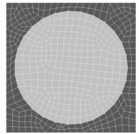
첫 번째 모델은 단면을 봤을 때 정사각형 단위 영역의 중앙 에 원 형태의 강화섬유 하나가 있는 경우로 Fig. 2와 같다.
Fig. 2 Cross section model 1
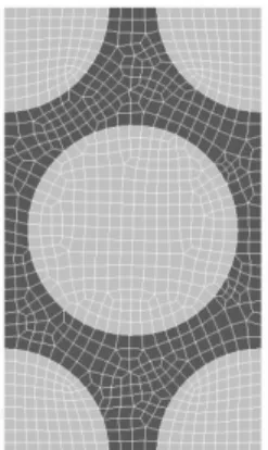
두 번째 모델은 중앙에 원 형태의 강화섬유 하나, 각 꼭짓점에 사분원 형태의 강화섬유가 있는 경우를 들 수 있다.
Fig. 3 Cross section model 2
세 번째 모델은 중앙과 각 꼭짓점에 섬유가 있지만 두 대각선이 60˚의 각을 이루는 경우로 만들었다.
Material property
X face(vertical plane of 1-axis) Y face(vertical plane of 2-axis) Z face(vertical plane of 3-axis)
X- X+ Y- Y+ Z- Z+
E11 U=0
V,W:free
U=Lx
V,W:free
V=0 U,V:free
V=0 U,V:free
W=0 U,V:free
W=0 U,V:free
E22 U=0,
V,W:free
U=0, V,W:free
V=0 U,W:free
V=Ly
U,W:free
W=0 U,V:free
W=0 U,V:free
G12 V=0 V=0.5Lx U=0 U=0.5Ly W=0 W=0
G23 U=0 U=0 W=0 W=0.5Ly V=0 V=0.5Lz
Table 1 Boundary conditions Fig. 4 Cross section model 3
2.3.2 물성치 대입 및 경계조건, 변위 설정
모델을 만든 후 강화섬유와 모재의 물성치를 지정하고 2차원의 경우 2,3방향의 순수 인장조건과 전단조건을 표현 할 수 있는 경계조건을 부여하였고, 3차원에서는 1,2,3방향 모두에 대하여 순수 인장조건과 전단조건을 부여하여 각 모델마다 해석을 수행하였다. 각 요소들이 동일한 조건하에 있도록 하중이 아닌 변위를 이용한 경계조건을 설정하였다. 자세한 경계조건은 Table 1과 같다.
2.3.3 해석
EDISON홈페이지의 CASAD Solver를 이용하여 해석을 진행한 후 에너지 식을 이용하여 값을 구한다. 유한요소해석을 통해 순수 인장조건과 전단조건을 경계조건으로 주었는데, 만일 복합재가 등가물성으로 이루어져 있다고 가정하면 경계 조건에 의해 각 경계조건마다 변형률 1가지만 값이 존재하고 나머지는 0이 된다. 그러므로 부여된 경계조건에 따라 해석 후 변형 에너지를 알면 해당 방향의 영의 계수를 계산할 수 있다.
해석을 통해 나온 에너지는 등가모델의 에너지와 같을 것이 므로 응력과 변형률을 구한 후 에너지를 계산해 주면 등가 물성을 얻을 수 있을 것이다. 관련 내용을 수식으로 표현하면 다음과 같다.
(2)
: 등가물성
: 등가모델의 방향 응력
: 해석을 통해 얻은 방향 응력
: 방향 변형률
위의 식으로 에너지를 구한 후 부피로 나눠 를 구할 수 있다. 이러한 과정을 통해 2차원의 경우 , , 을 구해 주었고 3차원의 경우, , , , 을 구해주었다.
2.4 여러 가지 방법을 통해 구한 물성치의 비교
유한요소해석으로 구한 복합재 전체의 물성치 값과 수식으로 구한 물성치 값, 실험값을 비교해 보고 유한요소해석이 수식 계산보다 얼마나 더 적합한지 실험값에 얼마나 더 가까운지 등을 살펴보았다. 맨 앞의 실험값은 실제 실험을 통해 측정한 값이고(Soden, 1998), 수식값은 Chamis 모델을 이용해 계산한 값이다. Fig. 5와 6은 CASAD Solver를 이용해 해석한 결과 중 하나를 나타낸다.
Fig. 5 2-Dimensional analysis result of model 1 using CASAD solver
Boundary condition : 2 direction constant strain left : , right : (stress unit :TPa)
Fig. 6 3-Dimensional analysis result of model 1 using CASAD solver
Boundary condition : 1 direction constant strain left: , right : (stress unit :TPa)
1) Silenka E-Glass 1200tex(섬유 비율 :60%)
Material property
Experi mental
value
Theori tical value
Model 1 Model 2 Model 3
E22
(GPa) 16.2 12.861 16.426 13.981 14.630 E33
(GPa) 16.2 12.861 16.417 13.982 14.632 G23
(GPa) 5.79 4.833 3.225 5.917 4.229
Table 2 Material properties of silenka E-Glass 1200tex 2-dimensional model
Material property
Experi mental
value
Theori tical value
Model 1 Model 2 Model 3
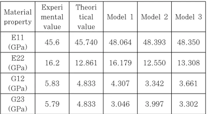
E11
(GPa) 45.6 45.740 48.064 48.393 48.350 E22
(GPa) 16.2 12.861 16.179 12.550 13.308 G12
(GPa) 5.83 4.833 4.307 3.342 3.661
G23
(GPa) 5.79 4.833 3.046 3.997 3.302
Table 3 Material properties of silenka E-Glass 1200tex 3-dimensional model
2) E-glass 21×K43 Gevetex(섬유 비율 :62%)
Matertial property
Experi mental
value
Theori tical value
Model 1 Model 2 Model 3
E22
(GPa) 17.7 13.642 17.966 14.839 15.448 E33
(GPa) 17.7 13.642 17.966 14.846 15.453 G23
(GPa) 6.32 5.126 3.471 6.469 4.511
Table 4 Material properties of E-glass 21xK43 gevetex 2-dimensional model
Material property
Experi mental
value
Theori tical value
Model 1 Model 2 Model 3
E11
(GPa) 53.48 50.873 53.639 53.459 53.297 E22
(GPa) 17.7 13.642 17.722 13.230 14.000 G12
(GPa) 5.83 5.126 4.739 3.538 3.849
G23
(GPa) 6.32 5.126 3.279 4.272 3.464
Table 5 Material properties of E-glass 21xK43 gevetex 3-dimensional model
3) T300(섬유 비율 :60%)
Material property
Experi mental
value
Theori tical value
Model 1 Model 2 Model 3
E22
(GPa) 11 9.260 10.225 9.503 9.849
E33
(GPa) 11 9.260 10.224 9.503 9.849
G23
(GPa) 3.93 3.804 2.926 3.708 3.305
Table 6 Material properties of T300 2-dimensional model
Material property
Experi mental
value
Theori tical value
Model 1 Model 2 Model 3
E11
(GPa) 138 139.6 140.125 141.126 141.123 E22
(GPa) 11 9.260 10.155 9.323 9.610
G12
(GPa) 5.5 4.906 4.313 3.633 3.860
G23
(GPa) 3.93 3.804 2.851 3.306 3.024
Table 7 Material properties of T300 3-dimensional model
3. 결 론
유한요소해석을 통해 구한 물성치와 수식을 이용해 구한 물성치 그리고 실험값을 비교하여 다음과 같은 결론을 얻을 수 있었다.
유한요소해석을 통해 물성치를 구할 때 세 가지 모델 중 영의 계수를 구하는데 가장 적합한 모델은 중앙에 원 형태의 fiber 하나가 있는 경우이다. 이 경우의 물성치는 다른 모델 들에 비하여 실험값과 비슷하다는 것을 확인할 수 있었다.
직사각형 모델의 경우에는 가로방향과 세로방향에 따라 섬유의 간격이 다르기 때문에 이로 인하여 배치방향성에 의한 물성치 변화가 생길 것이라 추측하였으나, 2차원에서 계산한 결과 방향에 따른 물성의 차이가 없음을 확인하였다. 또한 모델 2는 fiber가 배치될 때 윗줄과 아랫줄이 엇갈려서 배치되어 있다.
섬유간 간격이 같으나 힘을 주는 방향에 따라 혹은 shear가 작용할 때 E22가 특히 맞지 않음을 확인할 수 있다. 하지만 섬유간의 간격이 제일 가깝기 때문인지 전단 계수는 모델 2가 잘 맞는 것을 알 수 있다.
3차원의 경우 가장 실험값과 값이 비슷한 물성치는 길이 방향의 이다. 길이방향은 다른 방향에 비해서 섬유의 랜덤배열에 대해 큰 영향을 받지 않음을 알 수 있다. 같은 수의 섬유가 한쪽방향으로 몰려있거나 균일하게 분포되어 있는 것과 관계없어 모델에 따라 다르지 않고 비슷한 값을 가지게 된다.
요 지
복합재는 높은 비강도와 비강성을 가지고 있어 자동차, 항공기 등 전반적인 산업분야에서 널리 사용되는 재료이다. 우주 선의 노즐 부분과 같이 높은 온도뿐만 아니라 높은 압력이 작용하는 환경에서 사용하기 위한 재료로 복합재가 필요하다. 복 합재의 물성치를 아는 것은 매우 중요한데 모재(matrix)와 강화섬유(fiber) 각각의 물성치를 수치적으로 대입해 얻는 결과는 실험값과의 오차가 커 예측하는데 있어 더 정확한 방법이 필요할 것이다. 본 연구에서는 유한요소법을 이용한 EDISON용 CASAD solver 프로그램을 활용해 분석하였다. matrix와 fiber의 물성치를 대입해 복합재의 물성치를 구해 실험으로 측정된 물성치, 경험식으로 계산된 물성치와 비교를 하였다.
핵심용어 : 물성치, 복합재, 모재, 강화섬유, 유한요소법 감사의 글
본 논문은 2015년도 정부(미래창조과학부)의 재원으로 한국연구재단 첨단 사이언스·교육 허브 개발 사업의 지원을 받아 수행된 연구임(No, 2014M3C1A6038344).
References
Chamis, C.C. (1989) Mechanics of Composite Materials:
Past, Present, and Future, J. Compos., Technol. &
Res., 11, pp.3~14.
Ever, J.B. (2014) Finite Element Analysis of Composite Materials using ANSYS, Second Edition, pp.54∼56.
Hashin, Z. (1979) Analysis of Properties of Fiber Composites With Anisotropic Consitituents, J.
Appl. Mech., 46 pp.543∼550.
Lu, J., Zhu, P., Ji, Q., Feng, Q., He, J. (2014) Identification of the Mechanical Properties of the
Carbon Fiber and the Interphase Region based on Computational Micromechanics and Kriging Metamodel, Comput. Mater. Sci., 95, pp.172∼180.
Nakai, H., Kurashiki, T., Zako, M. (2007) Individual Modeling of Composite Materials with Mesh Superposition Method under Periodic Boundary Condition, 16th International Conference on Composite Materials, pp.1∼2.
Soden, P.D., Hinton, M.J., Kaddoura, A.S. (1998) Lamina Properties, Lay-up Configurations and Loading Conditions for a Range of Fibre-Reinforced Composite Laminates, Compos. Sci. & Technol., 58, pp.1011~1022.
Yun, S.H. (2000) The Finite Element Analysis for Calculations of Equivalent Elastic Constants Using the Homogenization Method, J. Comput. Struct.
Eng. Inst. Korea,, 13(1), pp.51∼61.