저항형 바이오 센서를 위한 브릿지 저항 편차-주기 변환기
정원섭
Bridge Resistance Deviation-to-Period Converter for Resistive Biosensors
Won-Sup Chung
요 약 저항형 바이오 센서를 인터페이싱하기 위해 브릿지 저항 편차-주기 변환기를 제안한다. 이 변환기는 선형
OTA(linear operational transconductance amplifier)와 전류-제어 발진기(current-controlled oscillator)로 구성된다.
브릿지 옵셋저항이 1 kΩ일 때, 프리러닝 주기는 1.824 ms이다. 변환기의 변 환 감도는 0-1.2 Ω의 저항편 범위에서 3.814 ms/Ω이다. 변환 특성의 선형 에러는 ±0.004 %이내이다.
ABSTRACT A bridge resistance deviation-to-period (BRD-to-P) converter is presented for interfacing resistive biosensors. It consists of a linear operational transconductance amplifier (OTA) and a current-controlled oscillator (CCO) formed by a current-tunable Schmitt trigger and an integrator. The free running period of the converter is 1.824 ms when the bridge offset resistance is 1 kΩ. The conversion sensitivity of the converter amounts to 3.814 ms/Ω over the resistance deviation range of 0-1.2 Ω. The linearity error of the conversion characteristic is less than ±0.004 %.
Key Word : resistive biosensor, resistive bridge circuit, bridge resistance deviation-to-period converter, interface
* Corresponding Author : Semiconductor Engineering Professor of Cheongju University ([email protected] ) Received : January 07, 2014 Revised : January 21, 2014 Accepted : January 27, 2014
Ⅰ. Introduction
Due to their high sensitivity, resistive biosensor bridges with four sensors can be widely used in many areas, especially biomedical measurement such as blood pressure, pulse and pulse transit time (PTT), and body temperature. In order to interface these sensors with digital systems, an accurate interface circuit converting a small change of resistance into a digital readout is required. A simplest
approach of converting the bridge resistance
deviation into a digital form is to convert the unknown resistance to frequency or time interval. Resistance-to-frequency conversion is mainly based on a relaxation oscillator [1], [2], which consists of a resistive bridge followed by an analog voltage differentiator (i.e., differential amplifier or differential integrator).
On the other hand, resistance-to –time interval conversion is based on pulse-width modulators (PWMs) [3] or current- tunable Schmitt triggers [4]. The former consists of a resistive bridge followed by PWMs and a digital time differentiator, while the latter by
voltage-to-current converters, current-tunable Schmitt triggers, a ramp voltage generator, and a digital time differentiator. These converters allow linear conversion of resistance deviation over time with high sensitivity. The main disadvantages of the converters are their complex circuit configurations and relatively low conversion linearity.
In this paper a new simple bridge resistance deviation-to-period(BRD-to-P) converter with high linearity is presented. The converter consists of a linear operational transconductance amplifier (OTA) and a current-controlled oscillator (CCO) formed by a current-tunable Schmitt trigger and an integrator.
Ⅱ. Circuit Description and Operation
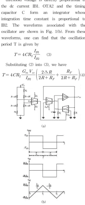
Fig. 1(a) shows the circuit diagram of the proposed BRD-to-P converter. The resistive biosensor bridge provides the voltage outputs given by
∆
(1)
where VCC is the source exciting the bridge and ΔR represents the change in resistance of the biosensors and RFis fixed resistance for free running oscillation when ΔR is zero. The bio- sensor bridge output voltage VOB is converted into its corresponding dc current IB1 by the linear OTA marked LOTA
∆ (2) where Gmis the transconductance gain of the LOTA. This dc current IB1 controls the oscillation period of the CCO so that the oscillation period is proportional to ΔR of the resistive biosensor. Two voltage amplifiers
(one is composed of the comparator and R1 and the other OTA1 and R2) connected in a positive- feedback manner form a Schmitt trigger whose
threshold voltage is directly proportional to the dc current IB1. OTA2 and the timing capacitor C form an integrator whose integration time constant is proportional to IB2. The waveforms associated with the oscillator are shown in Fig. 1(b). From these waveforms, one can find that the oscillation period T is given by
(3)
Substituting (2) into (3), we have
∆
(4)
(a)
(b)
Figure 1. (a) Circuit diagram of the proposed bridge BRD-to-P converter. (b)Output waveforms of the BRD-to-P converter.
Equation (4) indicates that the oscillation period is linearly proportional to ΔR of the resistive biosensor. The digital information can be obtained by counting the period T
with an external clock. The conversion sensitivity of the converter is given by
∆
(5)
It is noticeable that the conversion sensitivity can be controlled by the dc bias current IB2.
Ⅲ. Linear OTA
A circuit diagram of a LOTA designed for the BRD-to-P converter is shown in Fig.2 [5], [6]. It consists of a linear transconductor formed by transistors Q1~Q8 and an emitter- degeneration resistor RE, a translinear current gain cell Q9~Q12, and three Wilson current mirrors Q13~Q21. The LOTA converts the differential input voltage Vin into the single- ended output current Iout expressed as follows:
∈
∈ (6)
The transconductance gain Gm is given by (IY/IX)(1/RE). Equation (6) indicates that the transconductance gain of the LOTA can be adjusted by varying the ratio of the dc bias currents IY and IX. The input linear range of the LOTA is
∈≤
Figure 2. Circuit diagram of a LOTA designed for the BRD-to-P converter.
Ⅳ. Experiment Results
The LOTA circuit shown in Fig. 2 was breadboarded using the commercially available transistor arrays. The transistor arrays used were 2N2222 (npn) and 2N2907 (pnp). The resistors were RC =150 kΩ and RE = 1 kΩ.
The current sources were implemented with a Wilson current-mirror circuit. The bias currents IX and IY was set to 50 μA and 10 mA, respectively. The supply voltage VCC was 5 V and VEE was - 5 V. The measured linearity error in its dc transfer characteristic of the LOTA was less than ±0.2 % in the differential input voltage range of ±20 mV.
The BRD-to-P converter circuit shown in Fig. 1(a) was built using the following discrete components: LM13600 for the OTA1 and the OTA2, LM318 for the comparator.
The passive component values were adopted as follow: C = 5 nF, R1 = 10 kΩ, R2 = 2 kΩ, and RF = 1 ΩThe bias current IB2 was set to 10.4 μA. All measurements were performed at the supply voltages of VCC = 5 V and VEE
= - 5 V.
One arm of the bridge was constructed with a resistor of 1 kΩin series with a potentiometer of 10 Ω. All resistors are 0.5 %
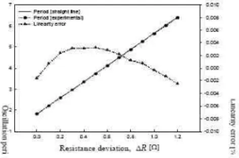
tolerance. The free running period of the converter is 1.824 ms when the bridge offset resistance R is 1 kΩ. Fig. 3 shows the measured period changes when ΔR was changed in 0.1 Ω steps from its fixed offset value of 1 kΩ. Resistance was measured using the Agilent digital multimeter type 3458A, and the HP frequency counter 53131A with a resolution of 0.01 μs in "period mode" was used to measure the period of the output rectangular waveform. Fig. 3 indicates that the conversion sensitivity of the converter amounts to 3.814 ms/Ω over the resistance deviation range of 0-1.2 Ω.
Figure 3. Measured period versus resistance deviation and its linearity error.
This sensitivity is comparable to that of the previous work [4]. The linearity error of the conversion characteristic is less than ±0.004
%, which is about three times lower than that of the previous work.
Ⅴ. Conclusions
A new circuit has been described which converts a resistance change in the bridge into its equivalent period change. The design principle and circuit configuration of the converter is simple. Besides these, the
converter features high sensitivity and linearity for small change of the resistive biosensors. Because of these advantages, the converter is expected to find wide applications in the signal processing of resistive bridge sensors.
References
[1] K. Mochizuki and K. Watanabe, "A high-resolution, linear resistance-to-frequency converter", IEEE Trans. Instrum. Meas., vol.
45, no. 3, pp.761-764, June 1996.
[2] S. Kaliyugavaradan, "A linear resistance-to-time converter with high resolu- tion", IEEE Trans.
Instrum. Meas., vol. 49, no. 1, pp. 151-153, Feb.2000.
[3] C. B. Morlan, B. O. Buafull, G. M.
Morales, and A. Regueior-Gomez, "A low-cost circuit with direct digital output for pressure measurement", IEEE Trans.
Instrum. Meas., vol. 48, no. 4, Aug. 1999.
[4] H. Kim, W.-S. Chung, S.-H. Son, and H.-J. Kim, "A bridge resistance deviation-to-time interval converter for resistive sensor bridges", IEICE Electronics Express, vol. 4, no. 10, pp.326-331, May 2007.
[5] W.-S. Chung, K.-H. Kim, and H.-W.Cha,
"A linear operational transconductance amplifier for instrumentation applications", IEEE Trans. Instrum. Meas., vol. 41, no. 3, June 1992.
[6] W.-S. Chung, H.-W. Cha, and S.-H. Son,
"A low-voltage low-power bipolar transconductor with high linearity", IEICE Trans. Fundamentals, vol. E88-A, no. 1, pp. 353-356, Jan. 2005.
저자약력
정 원 섭(Chung Won-Sup) 정회원
1977.02.26. 한양대학교 공학사 1979.02.24 한양대학교 공학석사 1987.01.16. (일)시즈오카대학교
공학박사
<관심분야> 반도체, 트렌지스터, 잔기전자회로