A Hierarchical Multicast Routing Protocol based on Zone Routing Technique for Wireless multi-hop Network
1)
Yi-Qi Gui * , Jie Zhang * , Dong-Il Yang **
무선 다중 홉 네트워크에서의 지역 기반의 계층적 멀티캐스트 라우팅 프로토콜
계 이 기 * , 장 걸 * , 양 동 일 **
Abstract
In wireless multi-hop network, many applications need multicast communication where the group leader needs to send data to all members of the group. Multicast routing provides a balanced, efficient, and fairness network environment for the group members. However, large load for transmission management to leader node and signal interference between several paths for multi-hop links always took long transmission delay and low throughput efficiency. In this paper, we propose a Zone-based Hierarchical Multicast Routing Protocol (ZHMP). This routing protocol is designed based on zone routing schemes, where proactive routing is applied for intra-zone node level multicasting and reactive routing is used for searching inter-zone paths. By each hierarchical and independent multicast working in separated zones, load of multicast source node will be distributed by several zone-level routings for a better load balance and signal interference between each multi-hop paths will be resisted for a maximum multicast throughput.
▸Keyword : Zone, Muliticast, Hierarchical, Interference, Independent
요 약
멀티캐스트 라우팅은 무선 다중 홉 네트워크에서 일대다 통신을 위하여 많은 영역에서 이용되며 멀티캐스트 그 룹 멤버에게 효율적이고 공평한 통신 환경을 마련한다. 하지만 그룹 멤버의 통신 관리, 각 전송 경로간의 신호간섭 등 요인은 멀티캐스트 소스 노드에게 비교적 큰 부하를 발생시키고 전체 멀티캐스팅의 효율을 저하시킨다. 본 논문 에서는 “지역 기반의 계층적 멀티캐스트 라우팅 기법”이라고 하는 새로운 라우팅 기법을 제안하였다. 이 라우팅 기 법은 지역 기반 라우팅 프로토콜의 속성을 기반으로 프로액티브 라우팅 기법을 지역 내부 노드 레벌의 멀티캐스팅 에서, 리액티브 라우팅 기법을 지역 레벌의 경로 설정에 적용하여 설계하였다. 계층적이고 독립적인 멀티캐스팅이 서로 분리된 지역에서 작동함으로서 멀티캐스트 소스 노드의 부하를 분산시켰고 다중 경로사이의 신호 간섭을 최대
∙제1저자 : Yi-Qi Gui 교신저자 : Dong-Il Yang
∙투고일 : 2010. 12. 02, 심사일 : 2010. 12. 07, 게재확정일 : 2010. 12. 31.
* 강원대학교 컴퓨터정보통신공학과 박사과정(Dept of Computer and Comunications Engineering, Kangwon National Univ)
** 한림성심대학 인터넷비즈니스과 교수(Dept of internet bussiness, Hallym University College)
한 회피하여 이상적인 멀티캐스트 전송률을 실현할 수 있었다.
▸Keyword : 지역, 멀티캐스트, 계층적, 방해, 독립성
Ⅰ.Introduction
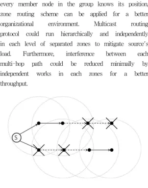
In these years, with grown of the technology and popularity of the internet, applications that require multicastings are becoming more widespread, a lot of multicast routing protocols are proposed for high throughput, low energy cost. Multicast utilizes network infrastructure efficiently by requiring the source to send a packet only once, even if it needs to be delivered to a large number of receivers. Some recent works have explored MAC protocols for reliable multicast[1]. In multicast routing with MAC protocol, as a group leader, multicast source node has responsibility to manage all messages for request or response from its neighbor group members or forwarding nodes such as RTS/CTS and ACK. It becomes large load to the leader node, cause higher delay and result in lower throughput. Low efficiency is also due to signal interferences between multi-hop multicast path, traffic within several multi-hop paths from leader to members may interfere each other by RTS/CTS interference and cause unexpected transmission delay[2]. While a node is sending data to the next node, other nodes within the source and neighbor's transmission range must set NAV and keep silent. Certainly, this kind of interference also happens between two or more nearby multicast paths as shown in Fig. 1. In the upper path of Fig.
1, the 4th node does not have any interference from any nodes among its path, however it have CTS interference from the node in the below path.
Therefore, more efficient routing protocols are required to solve these problems to design a better multicast map for a large area MANET.
As one of solutions for above problems, we propose a Zone-based Hierarchical Multicast Routing Protocol. This routing protocol is designed based on schemes of zone routing protocol. By the GPS, once
every member node in the group knows its position, zone routing scheme can be applied for a better organizational environment. Multicast routing protocol could run hierarchically and independently in each level of separated zones to mitigate source's load. Furthermore, interference between each multi-hop path could be reduced minimally by independent works in each zones for a better throughput.
Fig. 1. Signal interference between two paths.
Dotted-circle for each node's transmission range. In 802.11, other nodes inside the circles will sense RTS or
CTS and keep silence.
Ⅱ. Signal interference and RTS/CTS handshake on wireless network
In wireless network, ideal data throughput or
path establishment for a constant network connectivity
are always giving a lot problems for quality of
service(QoS). The signal collision can be seen as one
of main reasons of these problems(ex. hidden
terminal problem, exposed terminal problem). It
happens because the sent off signal in wireless
environment is not directionally reach to one
position among the transmission channel, the
receiving one may sense a lot signals around it but
it difficult to convince the correct one, and also, the
receiver is impossible to listen the signals while it is
sending data to someone else.
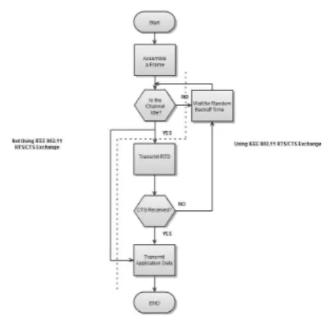
As a resolution of these problem, CSMA/CA (Carrier sense multiple access with collision avoidance) is carried out with the ethernet 802.3. In this protocol, a station wishing to transmit has to first listen to the channel for a predetermined amount of time so as to check for any activity on the channel.
If the channel is sensed "idle" then the station is permitted to transmit. If the channel is sensed as
"busy" the station has to defer its transmission.
IEEE 802.11 inherits the property of CSMA/CA and presents a RTS(Request to send)/CTS(Clear to send) handshake protocol to reduce the signal collision problem. It solve the hidden terminal problem, and originally fixed the exposed terminal problem as well. In this protocol, a node wishing to send data initiates the process by sending a RTS signal. The destination node replies with a CTS signal. Any other node sensing the RTS or CTS signal should set NAV(Network allocation vector) and refrain from sending data for a given time. During the amount of time included in NAV, the node which is not a part of the transmission should wait before trying to get access to the medium included in any RTS or CTS signal. The protocol was designed under the assumption that all nodes have the same transmission range. The process illustrated in Fig. 2 and Fig. 3.
Fig. 2. An example of RTS/CTS handshake and a timeline of packets exchange. In this instance, node 3 senses node 1's RTS, at the same time, node 4 may sense node 2's
CTS if the connection between node 1 and node 2 is established. They have to wait for a time period(include in
NAV) until node 1 and node 2 finish their transmissions
Fig. 3. Simplified Algorithm of CSMA/CA
The CSMA/CA and RTS/CTS handshake greatly solved signal collision problems in wireless network, but they also bring other weakness to wireless network such as reduced data throughput, unfairness of channel occupation, and so on. For example, assuming that ten nodes are positioned at a equal transmission range, while two of them are having communication, other eight nodes should not do anything but wait. We confirm this kind of instance as RTS/CTS interference.
Ⅲ. A Hierarchical Multicast Routing Protocol
1. Overview of multicast routing protocols The goal of multicast routing in a MANET is to discover the most recent topology of a continuously changing network to find correct routes to a specific node group. Multicast routing protocols in a MANET inherits unicast routing's schemes and can be classified into proactive routing (table-driven) such as Multicast Optimized Link State Routing(MOLSR)[3]
and reactive routing (on-demand) such as Multicast Ad hoc On-Demand Distance Vector routing(MAODV)[4], On-Demand Multicast Routing Protocol(ODMRP)[5].
As an extension of Optimized Link State Routing(OLSR),
MOLSR takes benefit of the topology knowledge
gathered by the OLSR protocol to build multicast
trees. The trees are updated whenever a topology change is detected. As a proactive routing protocol, MOLSR generates a big number of control messages which may cause large overhead to upkeep its paths in mobility network. Above multicast routing protocols provide high efficiency for one to many group routings in wireless network. However, reliability becomes an exact problem in multicast routing, because the multicast protocols dose not provide carrier sense algorithms such as in CSMA/CA. Jain and Samir R. Das proposed a MAC layer multicast protocol which performs multicast RTS/CTS exchange with all neighbor nodes on a multicast group. The protocol challenges the reliability in multicast like in unicast. But as we mentioned in section II, signal interference such as in RTS/CTS handshake may bring performance deteriorations in unicast routing and it may get the worse (e.g., more transmission delay) on one to many multicast routing.
2. Reviews of multi-hop routing on wireless network In a wireless multi-hop network, packets are delivered from source to destination by a few numbers of intermediate nodes among a created hop-by-hop path to improve the network scalability compare to managed wireless single-hop network. In multi-hop networks such as ad-hoc network, nodes do not start out familiar with the topology of their networks, while they have to discover it instead.
The basic idea is that a new node may announce its presence and should listen for announcements broadcast by its neighbours. Each node learns about nodes nearby and how to reach them. To routing in multi-hop networks, the path to reach a destination from a source is dynamically established by the intermediate nodes(hops) which are chosen by the connectivity of network and efficiency of QoS.
Routing schemes in multi-hop networks can be classified as three types: proactive routing - which calculate routes before the one is needed; reactive routing - only calculate the routes when it is needed;
and hierarchical routing - use both proactive and reactive routing hierarchically for each advantages.
A. Proactive routing
In proactive routing protocols, each node periodically distributes the routing tables throughout the network to maintain fresh lists of destinations and their routes, and every path to the destinations will be decided by the routing tables before starting communication. An advantage of this routing protocol is low latency of route discovery. However, it's disadvantage is a high communication overhead of control message for network maintenance. DSDV(Destination Sequenced Distance Vector), LSR(Link State Routing) and OLSR(Optimized Link State Routing) are the example of proactive routing protocol.
B. Reactive routing
In reactive routing protocols, a route is usually find by flooding the network with route request messages on demand. The paths are established only the communication is needed, RREQ(Route Request) and RREP(Route Reply) packets are exchanged from source to destination for route discovery. Low control overhead to whole network, good reaction on restructuring and failures are the advantages of this routing protocol, while high latency time in route discovery is the weakness of it. Examples of reactive routing protocol are DSR(Dynamic Source Routing), AODV(Ad-hoc On-demand Distance Vector), etc.
3. Zone Routing Protocol(ZRP) - a Hierarchical routing
As a hierarchical routing protocol, Zone Routing
Protocol, named by ZRP, combines both proactive
and reactive routing's properties. It reduces the
control overhead of proactive routing protocols and
decrease the latency caused by routing discover in
reactive routing protocols[6]. In this protocol, the
network is divided into several non-overlapping
zones. Each node knows the node connectivity within
its zone by proactive routing. Therefor, if the source
and destination is in the same zone, the packet can
be delivered immediately. Most of the existing proactive routing algorithms can be used as the inside zone routing for ZRP. For a zone level routing, route discovery will happen reactively by route request(RREQ) /route response(RREP) handshake.
An RREQ will be sent from source and forwarded by each zone until it finds a zone which contains the destination, on receiving the RREQ, destination sends an RREP on the reverse path back to the source. The structure of ZRP is illustrated in Fig. 4.
Fig. 4. A ZRP topology, dotted line for inter zone link and real line for intra zone link. Node A learns about its neighbours, using any proactive routing protocol. And node B, D, E, J, H are for discovering the outside zone
nodes (K, L)by using reactive routing protocols.
4. Zone-based Hierarchical Multicast Routing Protocol(ZHMP)
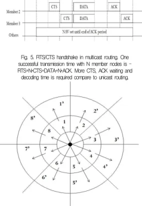
An extension to IEEE 802.11 protocol providing reliable multicast MAC protocol is proposed by Shweta Jain and Samir R. Das, which presents RTS/CTS handshake in multicast routing. However, the traffic delay in this routing protocol may cause unexpected overhead by time for searching a route, CTS or ACK waiting time in Fig. 5. and retransmission time for aborted transmissions.
Fig. 5. RTS/CTS handshake in multicast routing. One successful transmission time with N member nodes is - RTS+N*CTS+DATA+N*ACK. More CTS, ACK waiting and decoding time is required compare to unicast routing.
Fig. 6. ZHMP structure
The proposed ZHMP is on the purpose of network topology with minimal overhead on traffic of routing discovery and delay from signal interference. It's carried out based on ZRP schemes. In Fig. 6, different with ZRP, the network is considered as several levels of circle to fit a multicast group and each circle is divided into several zones for an idealize management.
It's formed by two sub-routings: intra-zone multicast
routing (proactive), for inside zone multicasting and
inter-zone unicast routing(reactive), to deliver data from one
zone to its sub-level zone. In each separated zone, all
link state informations are gathered and distributed
to every member nodes for a multicast path discovery
and entry/exit node selection. Entry node is chosen as
a leader node for its intra-zone multicasting and exit
node is chosen for routing discovery on zone-level
paths. Each exit node searches and creates a path to its sub-level zone's entry node for forwarding data from source to any zone which belongs to the multicast group in Fig. 7.
Fig. 7. One part of ZHMP topology, hierarchical multicasting runs inside each zones.
In ZHMP, the entry node of each zones will act as a tree node and for a fairness condition, it will be chosen from multicast member nodes. Source will relay the route discovery and intra-zone multicasting to each entry nodes, it only takes responsibility to transmission with entry node of first level zones.
Intra-zone multicast path is already be established while the zone is created(proactive scheme), entry node runs multicasting by the path and relaying the zone-level path discovery and data forwarding to its exit node. By hierarchically routing running in each independent zones, multicast paths will not only be discovered by source but also can be discovered by each level of zone. All the response messages such as CTS or ACK and retransmission request message could be managed by entry nodes instead of source node as a better topology to reduce interference than previewed multicast routings with RTS/CTS handshake.
Zone-level exit-to-entry link is a very important factor in ZHMP, a broken node-level intra-zone link only influence one path and can be recovered immediately as in a smaller environment. However, all its sub-level zones will lost connection and not be easily recovered for a broken zone-level link, even reactive routing is applied on. That is because zone-level link
recovery brings overhead of entry or exit node re-selection. As one solution, for a continuous transporting environment, secondary entry and exit node can be selected in each zone and establish a backup path to deal with broken zone-level links.
5. Entry & exit node selection in ZHMP
The path from entry node to exit node will be established by proactive routing(LSR), entry node gathers all node by node link informations in current zone and stores them in its routing table. With the routing table, the paths to all its zone-member nodes including the exit node will be created and sub-level intra zone multicasting of ZHMP may run with the paths. While a multicast path has to cross the zone to its sub-level zones, entry node will forward the RREQ to its zone-member exit node, and the exit node will deliver the RREQ to its sub-level entry node to establish a zone to zone path. The following pseudo codes explained how to going route discovery with entry and exit node in ZHMP.
Entry & Exit node selection algorithm / /receiving RREQ, entry node
if node.position==entry{
if RoutingTable.CheckNode(RREQ.Destination)==TRUE Reply(RREP);
else{
path = SetPath(RoutingTable.ExitNode);
ForwardRREQ(path);
} }
//receiving RREQ, exit node else if node.position==exit ForwardRREQ(SubLevel(EntryNode));
//receiving RREQ, other members else
ForwardRREQ(path);
One of important works to design a ZHMP is how to chose entry & exit node in each zones for a better efficacy. First of all, entry node must have a link to connect with its upper level zone's exit node, so the position can not be sided too deeply into the zone.
Second of all, an entry node should have most
powerful ability to run multicasting more efficiently.
For a better performance, we propose to apply a weighted algorithm[7] for intra zone multicasting.
In this algorithm, the entry nodes (lead nodes) are chosen the most powerful one for inside zone multicasting by means of node's weight, calculated by number of their neighbors with different hop distance by each correspond percentages. Exit nodes take charge of zone-level path discovery and data forwarding. Selection of exit node is not so complex.
Due to every node knowing their positions, the exit nodes can be chosen, which exists the shortest distance to its sub-level zone.
Ⅳ. Simulation: multicast tree routing vs.
ZHMP
We Evaluated our protocol ZHMP by a simple simulation. Our simulation compared throughput efficiency between traditional multicast tree routing and ZHMP. As simulation environment, we pick a part of hierarchical zone from ZHMP structure shown in Fig. 8. As a typical routing metric - minimal hop count(MHC) applied for multicast tree routing, paths will be created as shown in Fig. 8(b).
We assumed two situations for this multicast tree routing topology, one for maximum throughput - no signal interference and another one for the worst situation - full signal interference within each multicast paths. Fig. 8(a) shows hierarchical multicasting runs with ZHMP. Time for route discovery is not considered in this simulation.
(a) (b)
Fig. 8. One part of ZHMP topology, hierarchical multicasting runs inside each zones.
Fig. 9. Simulation results. Throughput variation with ZHMP and traditional multicast tree routing with none/full
interference.