1.
서 론고소작업대(Mobile Elevated Work Platforms; MEWPs) 는 작업대, 연장구조물, 차대로 구성되며 사람을 작업 위치로 이동시켜주는 설비이다1). 국내 고소작업대의 생산량은 연 1,000대이며, 2012년도 기준 보유는 약 4 만대가 있으며 종류별로는 차량탑재형이 5,000대, 시저 형은 34,000대, 자주형은 1,000대 정도를 보유하고 있 다2). 고소작업대의 사용 용도에 따라 소방, 절연, 일반 고소작업대로 나누어져 있고 현재는 건설분야(유리부 착, 외벽방수공사, 인테리어 등)에서 폭넓게 사용되고 있으며3), 최근 고층빌딩이 늘어남에 따라 고소작업대 의 사용이 많아지고 더욱 안정성이 높고, 더욱 환경친 화적인 제품이 요구되고 있다4). 수요가 증가하는 만큼 고소작업대로 인한 사망사고도 꾸준히 발생하고 있으 며 사망사고현황은 Table 1과 같다. Table 1에서 보면
2008년부터 2018년 4월말까지 사고발생일 기준으로 사 망사고 현황을 분석한 결과 총 발생건수는 250건이며 그 중에서 사고사망자수는 275명, 부상자수는 60명이 다. 고소작업대를 구성하고 있는 각종 부품과 구조물 등의 기계적 손상에 의한 사고현황은 Table 2와 같다.
총 발생건수 250건 중 기계적 손상에 의한 사고발생건 수는 42건으로 와이어로프 결함(13건, 31%), 선회대 고정볼트 결함(9건, 21%), 붐 용접부 결함(9건, 21%)순 으로 사고발생이 많았다5). 이와 같이 기계적 손상에 대한 사고를 예방하기 위하여 고소작업대를 구성하는 구조물과 부품에 대한 안전성 검증을 위하여 유한요 소해석을 이용하는 사례가 늘고 있다. Kim 등은 붐과 붐의 연결부분의 패드의 접촉조건과 붐 자체의 두께 를 변화시켜 응력과 처짐이 최소화되는 조건을 제시 하였다6).
Hong 등은 고소작업대의 안전성 검증을 위해 상용
**충남대학교 기계공학과 박사과정 (Department of Mechanical Engineering, Chungnam National University)
**충남대학교 기계공학과 교수 (Department of Mechanical Engineering, Chungnam National University)
https://doi.org/10.14346/JKOSOS.2019.34.5.1 http://www.kosos.or.kr/jkosos
고소작업대의 파손된 고정볼트의 피로분석에 관한 연구
최동훈*⋅김재훈**†
A Fatigue Analysis Study on the Fractured Fixing Bolts of Mobile Elevated Work Platforms
Dong Hoon Choi*⋅Jae Hoon Kim**†
†
Corresponding Author Jae Hoon Kim Tel : +82-42-821-6645 E-mail : [email protected] Received : June 24, 2019 Revised : August 14, 2019 Accepted : September 10, 2019
Abstract : The mobile elevated work platforms(MEWPs) consist of work platform, extending structure, and car, and it is a facility to move persons to working positions. MEWPs are useful but composed complex pieces of equipments, and accidents are caused by equipment defects.
Among them, accidents caused by fracture of the bolts fixing the extension structure and the turntable are increasing. In this study, fatigue failure and fatigue life of a turntable fixing bolt subjected to irregular fatigue load were analyzed by FEA. For this purpose, finite element modeling is proposed and structural analysis and fatigue analysis are performed simultaneously for fixing bolts. As a result of the structural analysis, it was confirmed that there is no risk of permanent deformation because the maximum stress acting on the fixing bolt is lower than the yield strength, and fatigue analysis was confirmed that the fatigue life is less than the design standard. The fatigue analysis results of this study can be effectively used for the design and the documentary assessment of the safety certification of the MEWPs by examining the fatigue life of the turntable fixing bolt.
Key Words : fatigue analysis, fatigue life, finite element analysis, mobile elevated work platforms(MEWPs), turntable fixing bolt
Copyright@2019 by The Korean Society
of Safety All right reserved.
Table 1. Number of injuries in the last 10 years
5)Year Total 2008 2009 2010 2011 2012
Fatalities 275 24 19 23 24 30
Injuries 60 9 6 4 8 5
Year 2013 2014 2015 2016 2017 2018.4
Fatalities 29 35 28 29 28 6
Injuries 2 8 7 9 1 1
Table 2. Number of accidents caused by mechanical damage in the last 10 years
5)Types of defects Accidents
Total 42
wire-rope 13
boom weld 9
turntable fixing bolts 9
work platform support 8
derrick cylinder 3
유한요소모델 프로그램인 ANSYS Workbench를 이용 하여 붐 조인트의 취약부분을 예측하였으며 해당 취약 부분의 응력을 최소화할 수 있는 붐 조인트의 최적설 계를 진행하였다7). Bang 등은 고소작업대의 붐의 각도 에 따른 응력분포 및 변형량 분석을 통하여 취약부분 을 파악하고 취약한 연결부분을 보완함으로써 안전성 을 증진시켰다8). 또한, Damian 등은 고소작업대의 각 부품에 대하여 유한요소해석을 통해 취약한 부분을 보 완할 수 있으며 이는 신속한 설계최적화를 가능하게 하였으며9) Jinquan 등은 각 부품의 재료가 요구하는 강 도에 적합한 재료를 선정하는 방법을 제시하였다10).
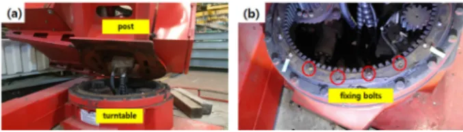
현재까지의 연구결과는 고소작업대의 붐에 대한 안 전성 해석, 붐과 붐을 연결하는 축 등에 대한 해석이 주를 이루고 있으나 신축형 붐, 붐조인트, 데릭실린더, 작업대 및 작업자의 하중을 모두 받는 선회대 고정볼 트에 대한 안전성과 반복하중이 집중되는 고정볼트의 파손 등에 대한 연구가 미흡한 실정이다. 또한, 선회대 고정볼트 결함에 의해 발생한 사고건수가 전체 사고건 수의 21%를 차지하고 안전검사를 받는 총 15종의 유 해위험기계기구 중 고소작업대가 보유대수를 고려할 경우 단위 재해강도가 가장 높은 점 등 고정볼트 파손 에 대한 연구의 필요성이 증대되고 있다11). 본 연구에 서는 파손된 선회대 고정볼트(Fig. 1)에 대하여 물리적 시험, 화학적 분석과 상용 유한요소모델 프로그램인 ANSYS Workbench로 구현한 고속작업대의 구조해석 을 수행하여 고정볼트에 발생하는 응력을 구했고, 동 시에 피로해석을 수행하였다.
Fig. 1. Failure scene of the fractured turntable fixing bolts: (a) the turntable and boom after accident, and (b) the fractured fixing bolts.
2.
고소작업대 구조 및 작동원리고소작업대는 Fig. 2와 같이 차량에 미들 프레임과 X형태의 프런트 아우트리거 및 리어 아우트리거, 360˚
회전가능한 선회대, 6단 붐 구조물, 1개의 탑승함 및 수평유지장치가 기본으로 장착된 구조로 되어 있으며, 주요기능은 붐의 좌우 360˚ 회전, 붐의 인출인입의 개 별 작동, 아우트리거의 인출 및 인입 등 다양한 기능을 가지고 있으며 이들 기능은 유압동력 발생장치인 유압 펌프 및 각부에 부착된 유압시스템에 의해 작동되고 조작은 아우트리거 수동조작반과 붐 조작용 무선 리모 콘 조작반으로 구성되어 있다12).
선회대 고정볼트(M16˟55L)는 스윙시스템과 포스트 베이스를 고정해주는 20개의 볼트이며 Fig. 3과 같이 좌우대칭으로 10개씩으로 구성되어있고 파손된 4개의 고정볼트는 R9, R10, L9, L10이다.
Fig. 2. Schematic of mobile elevated work platform working device.
Fig. 3. Twenty turntable fixing and fractured bolts.
3.
물리적 시험 및 화학적 분석 3.1 육안검사선회대 고정볼트 중 파손된 볼트(R10)의 파단면을 육안검사하면 포스트 베이스와 스윙시스템의 접촉부 근처의 볼트 나사골에서 파손된 것으로 피로특성을 보
였다13-15). 피로균열은 나사 골에서 시작하여 볼트 중심
으로 전파된 것으로 보이며, 파단면에 부드러운 피로 영역, 거친 피로영역 및 과부하 또는 최종파단 영역을 포함하는 피로파괴의 전형적인 세 가지 특징을 확인할 수 있다(Fig. 4).
3.2 화학적 성분 분석
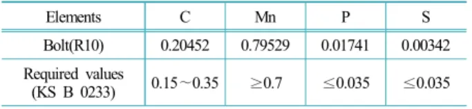
분광기(Thermo Scientific ARL iSPARK 8880)를 이용 하여 파단된 고정볼트의 화학적 성분을 측정한 결과는 Table 3에 나타내었고16-17), 이는 한국산업규격(KS B 0233) 강도구분 10.9의 화학적 성분기준을 만족함을 알 수 있었다19).
3.3 인장시험
계장화 압입시험기(프론틱스, AIT-U)를 이용하여 파 단된 고정볼트의 인장강도와 항복강도를 측정한 결과 는 Table 4에 나타내었고18), 이 또한 한국산업규격(KS B 0233) 강도구분 10.9의 기계적 성질(항복강도, 인장 강도)을 만족함을 알 수 있었다19).
Fig. 4. Macrograph and schematic of fracture surface of one of the fixing bolts.
Table 3. Chemical compositional analysis results of the fractured bolts (mass, %)
Elements C Mn P S
Bolt(R10) 0.20452 0.79529 0.01741 0.00342 Required values
(KS B 0233) 0.15 ∼ 0.35 ≥ 0.7 ≤ 0.035 ≤ 0.035
Table 4. Mechanical properties of the fractured bolts (MPa) Material Tensile strength Yield strength
Bolt(R10) 1,217 1,092
Required values
(KS B 0233) ≥ 1,000 ≥ 900
4.
유한요소모델 및 경계조건 4.1 고소작업대 모델본 논문에서 다루는 3.5톤 장축 고소작업대의 전고 는 2,985 mm이며, 붐의 각도 0°일 때 최대 인출 16 m, 붐의 각도 80°일 때 최대인출 28 m의 텔레스코픽 붐이 탑재되어 있다20). 선회대 고정볼트에 대한 구조해석과 피로해석을 위해 Fig. 5와 같이 선회대, 포스트, 1st-6th 붐 등으로 구성된 3D 모델을 SolidWorks로 모델링하였 으며 모델의 형상은 고정볼트에 최대굽힘응력이 작용 하는 붐각도가 0°인 형상으로 하였다.
4.2 Mesh 및 경계조건
Mesh 작업을 위한 3D 형상의 단순화를 위해 포스트 에 부착되어 있는 불필요한 용접 구조물 등을 제거한 뒤 Mesh 작업을 실시하였다. 사용된 요소의 종류는 사면체 요소이며 모델의 절점과 요소의 개수는 각각 120,549개 와 65,835개이다(Fig. 6). 축과 부싱의 재질은 SM45C, 포 스트 베이스는 SS400, 붐과 포스트는 ATOS80, 고정볼트 는 S45C, 스윙시스템은 S48C, 데릭실린더는 STC60이다.
사용된 재료의 물성치는 Table 5와 같다21).
Fig. 5. Geometrical model of the mobile elevated work platform.
Table 5. The mechanical properties used in structural analysis Materials Young's
modulus (GPa)
Poisson's ratio Density
(kg/m
3)
Yield strength
(MPa)
Tensile strength (MPa)
ATOS80 207 0.29 7,850 813 880
SS400 200 0.29 7,850 250 460
SM45C 207 0.3 7,600 490 686
S45C 205 0.29 7,850 1,092 1,217
S48C 200 0.27 7,700 365 610
STC60 202 0.27 7,800 520 588
Fig. 6. Finite element model.
Fig. 7. Boundary condition.
하중조건은 볼트의 경우 볼트 머리에 토크를 가해 볼트를 조여서 체결하므로 프리텐션값 105,000 N을 볼 트측면에 적용하고, 6th 붐의 끝면에 중력방향으로 최 대적재하중 (3.9 kN)과 작업대의 하중(1.7 kN)의 힘을 가하였으며 자중을 고려하였다22).
구조해석의 경계조건은 Fig. 7과 같다. 포스트 베이 스와 연결된 스윙시스템 하단 면을 고정지지하였고, 각각의 붐, 볼트 머리면과 포스트 베이스간의 접촉은 고착조건을 부여하였으며, 볼트를 제외한 포스트 베이 스와 스윙시스템간의 접촉은 분리없음 조건, 나사산이 있어 완전 체결되는 볼트 측면과 스윙시스템간의 접촉 은 고착조건을 부여하였다. 각 조인트와 핀은 원통지 지로 반지름방향과 축방향은 완전고정이고 회전방향 은 회전이 가능한 조건을 주었다23).
피로해석을 위해 하중조건 및 경계조건은 앞서 수행 한 구조해석의 조건과 동일하게 적용하였고 재료의 물 성치 외에 피로해석을 위한 고정볼트(S45C)의 S-N 곡 선정보를 입력하였다24-25). 반복하중은 Sine형태의 Zero- Based하중을 주었으며, Goodman의 피로방정식을 적용 하였다26-28).
4.3 구조해석 결과
구조해석의 결과는 Fig. 8과 같은 결과를 얻었으며 고정볼트(R10)에 작용하는 최대 von Mises등가응력은 552.64 MPa이며, 고정볼트의 항복강도인 1,092 MPa 이 하이며, 안전계수가 1.98로 고소작업대 설계기준 1.48 이상으로 고정볼트는 안전하게 설계되었음을 확인할 수 있다29).
4.4 피로해석 결과
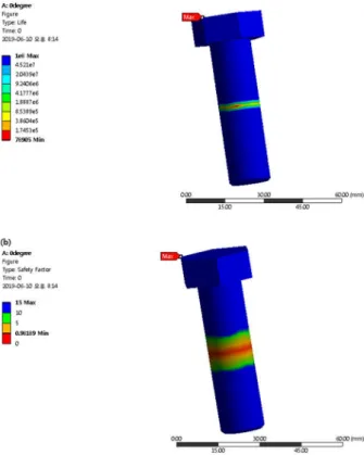
피로해석의 결과는 최대 von Mises등가응력이 작용 하는 지점인 포스트 베이스와 스윙시스템의 접촉부 근 처의 피로수명은 7.8905 × 10⁴ 회로 설계피로수명인 1 × 10⁵회 이하임을 확인하였고(Fig. 9(a)), 최소안전계수값 이 1.0이하인 0.98로 피로수명에 대한 안전설계에 부합 하지 않음을 확인할 수 있다(Fig. 9(b))30).
Fig. 8. Max. von Mises equivalent stress for the fixing bolt.
Fig. 9. Life(a) and Safety Factor(b) calculation.
5.
결론 및 고찰고소작업대에 반복하중이 작용하는 선회대 고정볼 트의 피로파손여부와 피로수명에 대해 유한요소해석
을 진행하였다. 본 연구를 통하여 얻은 결론은 다음과 같다.
1. 파손된 고정볼트에 대한 물리적시험과 화학적분 석 결과는 한국산업규격(KS B 0233) 강도구분 10.9의 화학적 성분기준과 기계적 성질(항복강도, 인장강도)을 만족함을 확인하였다.
2. 구조해석결과는 고정볼트에 작용하는 최대 von Mises등가응력이 볼트의 항복강도인 1,092 MPa보다 낮 고 안전계수가 설계기준인 1.48보다 높으므로 영구변 형에 대한 위험은 없는 것을 확인하였다.
3. 피로해석결과는 최소 피로수명이 7.8905 × 10⁴회 로 설계기준인 1 × 10⁵회 이하임을 확인하였으며, 이는 고소작업대를 장시간 반복적인 작업을 수행할 경우 피 로에 의해 고정볼트가 파손될 가능성이 있음을 예측할 수 있었다. 따라서, 제작사가 설계단계에서 피로해석을 실시하여 무한피로수명을 보장함을 입증하여야 하며 안전인증기관은 서면심사 시 피로해석결과를 확인하 여야 한다. 또한, 안전검사기관이 검사 시 균열 발생 및 균열 진전 여부를 비파괴검사를 통해 확인하여야 하며 10년 사용을 보장한 설계기준인 1 × 10⁵회 이전에 고정볼트를 교체한 결과에 대한 확인 절차가 추가되어 야 할 것으로 사료된다.
References
1) KS B ISO 16368, “Mobile Elevated Work Platforms”, 2010.
2) W. Shin, “Proposed Revision of Standard on Articles for Aerial Work Platform”, J. Korean Soc. Saf., Vol. 28, No. 7, pp. 9-13, 2013.
3) M. H. Kim and M. K. Lee, G. S. Park and I. D. Jang,
“Structural Analysis for 40m Articulated Elevation Work Platform”, The Korean Society for Precision Engineering, Autumn Conference, 2014.
4) Y. H. Bo et al, “A Stucy on a Structural Stability that Design the Main Frame of the Aerial Working Platform”, Proc. of the Mechanical Engineering Spring Conference, Vol. 11, pp. 344-345, 2011.
5) KOSHA, “In-depth Analysis Report of the Accidents at the Mobile Elevated Work Platform in the last 10 years”, 2018.
6) S. S. Kim, “FEM Analysis of the Boom Structure of an Aerial Lift Truck Considering the Clearance and Contact”, Spring Conference of the Korean Society for Precision Engineering, 2011.
7) J. M. Hong and J. H. Lee, “Optimal Design of Boom Joint
for 2.5Ton Class Aerial Lift Truck”, The Korea Society for Precision Engineering, Vol. 35, No. 8, pp. 769-775, 2018.
8) S. O. Bang and J. U. Cho, “Structure Analysis of Multi- Linked High Place working Vehicle”, The Korea Academy Industrial Cooperation Society, Vol. 12, No. 2, pp. 617-622, 2011.
9) D. Derlukiewicz and G. Przybylek, “Chosen Aspects of FEM Strength Analysis of Telescopic Jib Mounted on Mobile Platform”, Automation in Construction, Vol. 17, pp.
278-283, 2008.
10) J. Guo, H. He and C. Sun, “Analysis of the performance of Aerial work Platform Working Device Based on Virtual Prototype and Finite Element Method”, Energy Procedia, Vol. 104, pp. 568-573, 2016.
11) G. H. Choi and B. G. Loh, “Risk Assessment of Industrial Machines and Devices and Appropriateness of Their Safety Certification and Self-Declaration of Conformity”, J.
Korean Soc. Saf., Vol. 31, No. 1, pp. 1-6, 2016.
12) HANSIN SPECIAL EQUIPMENT CO., “Instruction Manual and Repairing Guide”
13) S. Molaei et al., “A Failure Analysis Study on the Fractured Connecting Bolts of a Filter Press”, Case Studies in Engineering Failure Analysis, Vol. 4, pp. 26-38, 2015.
14) L. Li and R. Wang, “Failure Analysis on Fracture of Worm Gear Connection Bolts”, Engineering Failure Analysis, Vol.
36, pp. 439-446, 2014.
15) O. Asi, “Failure of a Stud Bolt in a Ring Spinning Frame Textile Machine”, Engineering Failure Analysis, Vol. 13, pp. 963-970, 2006.
16) Z. W. Yu et al., “Failure Analysis of Connecting Bolts and Location Pins Assembled on the Plate of Main-shaft used in a Locomotive Turbocharger”, Engineering Failure Analysis, Vol. 15, pp. 471-479, 2008.
17) Z. W. Yu et al., “Failure Analysis on Connecting Components of Turbo-disk and Main-shaft used in a Locomotive Turbocharger”, Engineering Failure Analysis, Vol. 16, pp. 899-908, 2009.
18) M. T. Milan et al., “Failure analysis of a SAE 4340 Steel Locking Bolt”, Engineering Failure Analysis 11, pp.
915-924, 2004.
19) KS B 0233, “Mechanical Properties of Steel Bolts and Screws ”, 2005.
20) KISA, “Documents of Safety Certification”, 2013.
21) D. P. Hong, C. G. Park, B. K. Lee, Y. Hong and S. H.
Hwang, “Stress Analysis for 46kV Insulated Boom Design of 20m-class High Place Operation Car”, Proc. of the
Korean Society for Noise and Vibration Engineering, pp.
528-529, 2012.
22) J. K. Kwon, “Structural Analysis of Bolts”, CAD&
Graphics, 2012.
23) J. H. Lee and J. M. Hong, “Structure Analysis of Boom Joint for 2.5ton Class Aerial Lift Truck”, Spring Conference of the Korean Society for Precision Engineering, 2017.
24) G. H. Majzoobi, G. H. Farrahi and N. Habibi,
“Experimental Evaluation of the Effect of Thread Pitch on Fatigue Life of Bolts”, International Journal of Fatigue, Vol.
27, pp. 189-196, 2005.
25) S. Hanaki, M. Yamashita, H. Uchida and M. Zako, “On Stochastic Evaluation of S-N Data based on Fatigue Strength Distribution”, International Journal of Fatigue, Vol. 32, pp. 605-609, 2010.
26) K. S. Nam, D. W. Lee, J. G. Choi, M. H. Park, Z. Shang and S. S. Lee, “Structure and Fatigue Analysis of Pull-in Winch Frame using the FEA”, Spring Conference the Korean Society Mechanical Engineers, 2014.
27) J. H. Ko and D. M Kang, “CAE Analysis on Strength and Fatigue of Rear Door of Passenger Car”, Journal of the Korean Society of Manufacturing Process Engineers, Vol.
13, No. 3, pp. 63-69, 2014.
28) Y. J. Shin, C. H. Choi, S. G. Lee and J. H. Kim, “Fatigue CAE Analysis of a Rebar Bending Machine Roller”, Journal of the Korean Society of Manufacturing Process Engineers, Vol. 14, No. 2, pp. 75-80, 2015.
29) KS B ISO 8686-2, “Cranes-Design Principles for Loads and Load Combinations-Part2: Mobile Cranes”, 2004.
30) KS B ISO 16368, “Mobile Elevated Work Platforms- Design Calculations-Stability Criteria-Construction-Safety- Examinations and Tests”, 2010.