Development of a 4-DOF Industrial Robot System
Han Sung Kim1*
<Abstract>
In this work, a 4-DOF industrial robot system with three translational and one rotational motions which is widely used in palletizing applications is developed. In order for small robot manufacturing companies to develop their own robot systems for CNC machining and/or general automations, the analysis and design methods of a 4-DOF robot manipulator are presented and the development of a PC-based robot controller with EtherCAT are introduced. It is noted that the robot controller is developed by using Simulink Real-Time, which can provide an integrated environment of easier control algorithm development and data logging. Through position control and accuracy/repeatability measurement results, the developed robot prototype has comparable performances with commercial counterparts. In the future works, the advanced functions of industrial robots such as kinematic calibration, vibration suppression control, computed torque control, etc. will be investigated.
Keywords : CNC machines, Robot automation, Palletizing robot, Repeatability, EtherCAT
1* Corresponding author, School of Mechanical Engineering, Kyungnam University
(Email: [email protected])
1. Introduction
Recently, CNC machine industry introduces robot automation technology to machining process in order to reduce total cost and time. New CNC and MCT machines manufactured by oversea big companies are integrated with loading/ unloading, deburring, washing, and inspection automations by using industrial robots.
In this work, a typical 4-DOF palletizing robot is proposed to perform robot automation tasks with CNC machines such as loading/unloading and deburring. However, it is noted that the proposed 4-DOF robot can be used in general robot automation tasks. In order for small robot manufacturing companies to develop their own robot systems for CNC machining automations, the analysis and design of a 4-DOF palletizing robot manipulator and the development of a PC-based robot controller with EtherCAT (Ethernet for Control Automation Technology) are presented.
This paper is organized as follows. First, the kinematic analyses including forward/
inverse kinematics and Jacobian analyses are derived. Second, the robot manipulator design methodology is presented. Third, the robot controller development with EtherCAT and Simulink Real-Time is explained. Finally, the position control and accuracy measurement results are presented to show that the developed robot prototype performances are
good enough to be used in real machining automations.
2. Kinematics Analysis
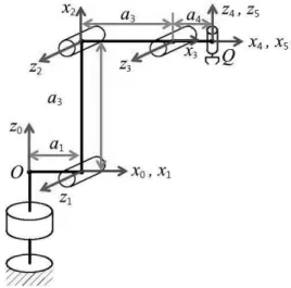
The proposed 4-DOF robot manipulator consists of four active revolute joints and one passive revolute joint in series as shown in Fig. 1, where the 4th revolute joint () is passive. Table 1 shows the D-H parameters of the 4-DOF robot manipulator. Referring to Fig. 2, the angle of link 4 is maintained to be parallel to the ground by two parallelogram linkages [1] (, ) and the joint 3 is rotated by the closed-loop linkage () and the rotary actuator 3 mounted on the axis.
Fig. 1 Kinematic modeling of the 4-DOF robot
Joint
1 0
2 0 0
3 0 0
4 0
5 0 0 0
Table 1. D-H parameters of the 4-DOF robot
2.1 Forward Kinematics
The forward kinematics is defined as the problem to find the end-effector position and angle ( , ) when the joint angles ( ) are given [2].
Using the homogeneous transformation matrices and the angle condition of
and , the end- effector position and angle can be obtained by
,
,
, (1)
2.2 Inverse Kinematics
The inverse kinematics is defined by the problem to find the joint angles ( ) when the end-effector position and angle ( , ) are given.
First, the joint angle 1 is determined by
Atan (2)
By summing the squares of the first and second equations of Eq. (1), Eq. (1) can be rewritten by
,
(3)
where . Eq. (3) denotes the forward kinematic equations of a 2-DOF planar robot with and .
Second, the joint angle 3 is obtained by
± cos (4)
where
and “-” sign is selected for the elbow-up solution.
Third, the joint angle 2 is calculated by
Atan (5)
where ∆ ,
∆ , and
∆ .
Finally, the joint angle 5 is obtained by
(6)
2.3 Jacobian Analysis
By differentiating Eq. (1) with respect to time, the velocity relation can be obtained. by [2]
(7)
where , , and the Jacobian matrix is given by
(8)Using the principle of virtual works, the statics relation is obtained by
(9)
where the joint torque and end-effector force vectors are and
, respectively.
3. Robot Manipulator Design
3.1 Workspace Analysis
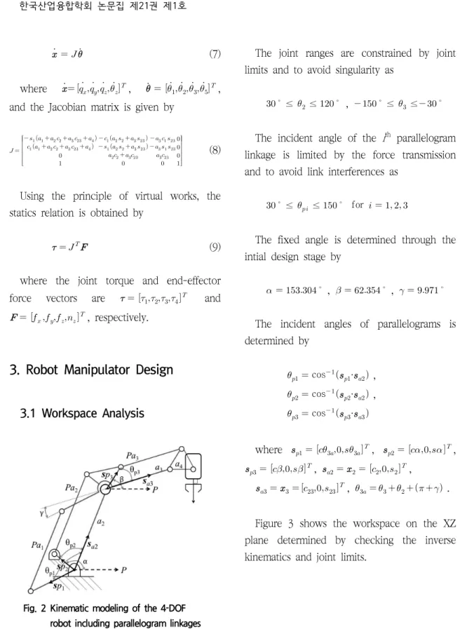
Fig. 2 Kinematic modeling of the 4-DOF robot including parallelogram linkages
The joint ranges are constrained by joint limits and to avoid singularity as
≤ ≤ , ≤ ≤
The incident angle of the ith parallelogram linkage is limited by the force transmission and to avoid link interferences as
≤ ≤ for
The fixed angle is determined through the intial design stage by
, ,
The incident angles of parallelograms is determined by
cos · ,
cos · ,
cos ·
where , ,
, ,
, .
Figure 3 shows the workspace on the XZ plane determined by checking the inverse kinematics and joint limits.
Fig. 3 Workspace on the XZ plane
3.2 Robot Prototype Development
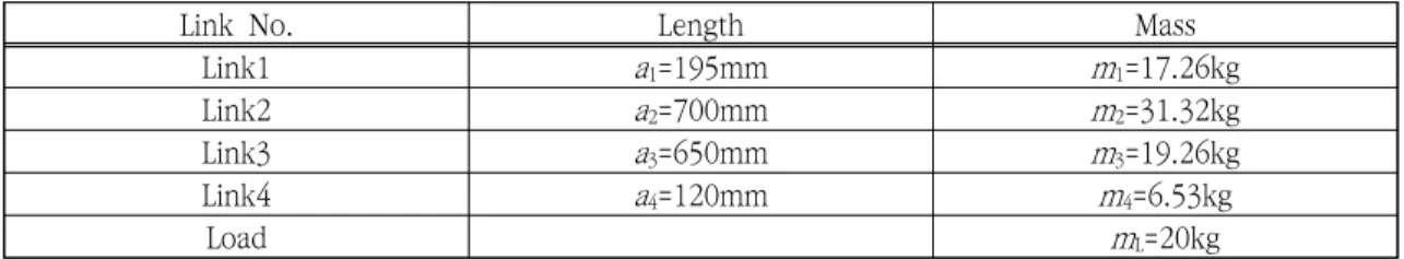
Through the workspace and structural analyses, the kinematic parameters and link masses are chosen in Table 2. Table 3 shows the actuator sizing results. In Table 3, the
motor shaft and gear output values are obtained from the motor and gear catalog values. The load shaft values are ideal ones and calculated with motor and gear ratio values.
Fig. 4 Robot Manipulator Prototype
Link No. Length Mass
Link1 a1=195mm m1=17.26kg
Link2 a2=700mm m2=31.32kg
Link3 a3=650mm m3=19.26kg
Link4 a4=120mm m4=6.53kg
Load mL=20kg
Table 2. Link lengths and masses of the robot prototype
Axis No. Power/
Gear ratio Items Motor shaft Load
shaft Gear output
rated max. rated max. rated max.
1 2.0kW/
121.119
Torque[Nm] 6.37 19.1 771.5 2,313.4 1,376 1,680
Speed[rps] 50 83.3 0.413 0.688 0.413 0.669
2 2.0kW/
114.050
Torque[Nm] 6.37 19.1 726.5 2178.4 649 800
Speed[rps] 50 83.3 0.438 0.730 0.438 1.070
3 1.5kW/
120.965
Torque[Nm] 4.77 14.3 577 1729.80 453 545
Speed[rps] 50 83.3 0.413 0.689 0.413 1.240
4 0.4kW/50 Torque[Nm] 1.3 3.8 65 190 44 73
Speed[rps] 50 100 1 2 1.166 2.166
Table 3. Specifications of the selected servo motors and gears
Using the inverse dynamics equations with the max. velocity of 1m/s and the max.
acceleration of 5m/s2, the max. torque among the actuators 1, 2, 3 is calculated by
[Nm] for 20kg payload. It is noted that max≤ Nm. Figure 4 shows the 4-DOF robot manipulator prototype.
4. Robot Controller Development
In this work, the PC-based controller with Simulink Real-Time is developed to provide the environment of easier control algorithm development and data logging for research.
As shown in Fig. 5, the control system consists of a Host PC (Development environment using Simulink Real-Time [3]), a Target PC (Real-time target and EtherCAT master), Servo drivers and I/Os (EtherCAT slaves) and Teach pendent (or MPG (Manual Pulse Generation)), where EtherCAT is an Ethernet-based fieldbus system and provides DC (Distributed Clock) for critical real-time control [4].
In Fig. 6, the robot control program is made up of following subsystems with 1msec control loop. [Mode Setting] EhterCAT ENI file setting, Mode of operation, Control word write, and Status word read. [Trajectory] Inverse kinematics, Trajectory generation, Control mode selection (Disable=-1, Home Position=0, Joint-space move=1, Cartesian- space move=2, Trajectory move=3). [Target Position] writing Target position on AC servo drive. [Actual
Position] reading Position actual value.
Figure 7 shows the control menu on the Teach Pendant and the robot simulator developed by using V-REP [5].
Fig. 5 Robot Control System Configuration
Fig. 6 Robot Control Program by Simulink
Fig. 7 Control Menu and V-REP Robot Simulator
5. Performance Experiments
5.1 Position Control Experiments
The line trajectory from (915, -500, 700) to (915,+500,700)[mm] with the max. velocity of 0.5m/s and the max. acceleration of 1m/s2 is generated. The errors at set points are within a hundred encoder pulses (divided by 220 (20-bit encoder)), however, between set points small delay occurs due to the velocity gain (damping) of the AC servo drive as shown in Fig. 8.
Fig. 8 End-effector Position and its Error
5.2 Accuracy/Repeatability Measurements
As shown in Fig. 9, position accuracy and repeatability are measured by Laser tracker for 5 points (P1-P5) [6]. During measurements, the robot is operated with full payload 20kg and 30% of max. velocity. From Table 4, the position accuracy is about ±0.024mm and the position repeatability is about ±0.0014mm.
Fig. 9 Accuracy Measurements by Laser Tracker
Condition Position Accuracy [mm]
P1 P2 P3 P4 P5
Payload (100%, 20kg) Velocity(30%)
±0.0490 ±0.0113 ±0.0104 ±0.0049 ±0.0242
Condition Position Repeatability [mm]
P1 P2 P3 P4 P5
Payload (100%, 20kg) Velocity(30%)
±0.0014 ±0.0002 ±0.0001 ±0.0003 ±0.0013
Table 4. Position Accuracy and Repeatability Measurements
6. Conclusions
In this paper, the design methodology of the 4-DOF palletizing robot manipulator and the PC-based robot controller development using EtherCAT are presented. Through performance experiments, it is shown that the robot system prototype has comparable performance than commercial ones. In the future works, the advanced functions of industrial robots such as kinematic calibration, vibration suppression control, computed torque control, etc. will be investigated.
Acknowledgment
This research was supported by The Leading Human Resource Training Program of Regional Neo industry through the National Research Foundation of Korea(NRF) funded by the Ministry of Science, ICT and future Planning(2016H1D5A1911017).
References
[1] Kong, M.X., You W., Du, Z.J., and Sun L.N.,
“Optimal Design of a 2-DOF High Dynamic Manipulator based on Parallelogram Mechanism,”
2010 IEEE/ASME Int. Conf. on Advanced Intelligent Mechatronics, pp. 242-247, Montreal, Canada, July 6-9, 2010.
[2] Tsai, L.W., Robot Analysis: The Mechanics of
Serial and Parallel Manipulators, Wiley, 1999.
[3] http://www.mathworks.com [4] http://www.ethercat.org
[5] http://www.coppeliarobotics.com
[6] ISO 9283:1998(en), Manipulating industrial robots–
Performance criteria and related test methods.
(Manuscript received November 24, 2017; revised December 28, 2017; accepted January 15, 2018.)
![Figure 7 shows the control menu on the Teach Pendant and the robot simulator developed by using V-REP [5].](https://thumb-ap.123doks.com/thumbv2/123dokinfo/4858645.529049/6.876.467.750.287.456/figure-shows-control-teach-pendant-robot-simulator-developed.webp)
