• 검색 결과가 없습니다.

PWSCC and System Engineering Development of Internal Inspection and Maintenance Methodology for RCS

N/A
N/A
Protected

Academic year: 2021

Share "PWSCC and System Engineering Development of Internal Inspection and Maintenance Methodology for RCS"

Copied!
15
0
0

로드 중.... (전체 텍스트 보기)

전체 글

(1)

PWSCC and System Engineering Development of Internal Inspection and Maintenance Methodology for RCS

Khaled Atya Ahmed Abdallah, Patricia Alves Franca de Mesquita, Norashila Yusoff, GungIhn Nam, JaeCheon Jung, YoungKwan Lee

*

Department of Nuclear Power Plant Engineering, KEPCO International Nuclear Graduate School, Ulsan

Abstract : Due to safety of the plant, it became very clear the importance of study occurrence reactor coolant system (RCS) issues specially the primary water stress corrosion cracking (PWSCC). The Systems Engineering (SE) approach is characterized by the application of a structured engineering methodology for the design of a complex system or component. Robotic devices have been used for internal inspection, maintenance and performing remote welding and inspection in high-radiation areas. In this paper, PWSCC overview and inlay and over lay welding methodology introduced, concept of robotic device that can be inserted into the piping via Steam Generator (SG) main way to access to primary piping of pressurized water reactor (PWR) is developed based on SE methodology. A 3D model of the inspection system was developed along with the APR1400 (Advanced Power Reactor)reactor coolant systems (RCS) and internals with virtual 3D simulation of the operation for visualization to prove the validity of the concept.

Key Words : PWSCC, SE approach, Robotic, Internal inspection, RCS pipe inspection

Received: November 18, 2015 / Revised: June 7, 2016 / Accepted: June 11, 2016

* 교신저자 : YoungKwan Lee, [email protected]

This is an Open-Access article distributed under the terms of the Creative Commons Attribution Non-Commercial

License(http://creativecommons.org/licenses/by-nc/3.0) which permits unrestricted non-commercial use, distribution,

and reproduction in any medium, provided the original work is properly cited.

(2)

[Figure 1] 3D Model of RCS by CATIA V5

1. Introduction

The PWR RCS major functions is to supply coolant flow to remove heat from reactor core and transfer it to SG, to serve as the 2nd barrier to the release of fission products from the reactor core to the environment. The 1st barrier is fuel cladding, to provide sufficient cooling to prevent fuel damage during all normal plant operations and anticipated transients, to circulate reactor coolant of the required chemistry and boron concentration, and to maintain reactor coolant pressure and inventory control. Very important to maintain the integrity of the Reactor Coolant Pressure Boundary (RCPB) throughout the plant’s design lifetime.

The most serious metallurgical issues facing the nuclear industry is stress corrosion cracking (SCC). PWR Components; Primary Water Stress Corrosion Cracking (PWSCC) discovered in the 80’s in Nickel-base Alloys, like Steam Generator Tubes, reactor pressure Vessel (RPV) Penetrations, and Nozzles. The most critical factor concerning SCC is that three preconditions are necessary and must be present simultaneously. The three necessary preconditions are: a susceptible ma- terial, a tensile stress component, and an aqueous environment. The elimination of any one of these factors or the reduction of one of these three factors below a specific threshold level can, prevent SCC. In order to prevent PWSCC from occurring it is required early detection and evaluation of flaws in terms of their nature, size, and location [1].

Whether via the NRC (United States Nuclear Regulatory Commission) or the German Federal Ministry for Environment, Nature Conservation and Nuclear Safety (BMU), the regulation au-

thorities of all nuclear power producing countries require each nuclear power plant (NPP) to compile an in-service inspection (ISI) programmed in order to guarantee the safe, and reliable op- eration of systems [2]. The objectives of an in-service inspection programmed are [3]:

1) To minimize plant cost arising from failures in plant systems and components.

2) To evaluate and detect defects that subse- quently should receive enhanced in-service inspection;

3) To make more effective use of available resources taking into account in-service inspection programmed requirements, “as low as reasonably achievable” (ALARA).

There is, therefore, a need to detect these flaws and evaluate them. By applying SE meth- odology, it is possible to specify problems, requirements, needs, and finally the solution for the PWSCC issue in RCS as in figure 1 by improve and develop internal inspection to reach to internal parts in RCS by a robotic system.

When applying the SE approach, the focus is

on the designing and analysis of the system as

a whole, as distinct from a specific focus on

(3)

[Figure 2] ASME code section III and section XI

the components or the parts. Therefore, the approach consists upon looking at a problem as whole, taking into account all the parts and all the parameters in an interconnected way [4].

2. Methodology and Skills

In this part we introduced project requirement, design engineering element, and specialty en- gineering attribute.

2.1 Design Engineering Element

2.1.1 Regulatory guide and standards ISI program will be provided for the exam- ination of the RCPB components and supports defined as Code Class 1. The program will reflect the principles and intent embodied in the ASME Boiler and Pressure Vessel Code, Section XI.

Specific Code Editions and addenda required by 10 CFR 50.55a are referenced in the Pre- service Inspection (PSI) and ISI programs, how- ever, the PSI program will meet all requirements for Section XI of the same edition as the ASME Code used for construction, and the ISI program will meet the ASME Code Section XI in effect in accordance with 10 CFR 50.55a.

Section XI Rules for ISI of NPP Components:

Section XI, provides requirements for examination, testing, inspection, repair, and replacement ac- tivities in a NPP. Figure 2 shows ASME code

section III, and ASME code section XI application.

Owner’s responsibilities include: provision of access to conduct the examination and tests;

development of plans and schedules which in- clude detailed examination and testing procedures for filing with the enforcement and regulatory authorities having jurisdiction at the plant site;

conduct of the program of examination and tests, system leakage and hydrostatic pressure tests; and recording of the results of the exam- inations and tests, including corrective actions required and the actions taken.

ASME B&PVC_Section XI_ General Requirements:

Scope of Section XI (IWA-1100) - Provides re- quirements for testing, examination, and inspection of components and systems, and repair/replacement activities in a NPP - Requirements of Section XI do not apply to flaws identified at times other than during periodic in-service inspection or repair replacement activities. Jurisdiction (IWA-1200) - With limited exceptions, Section XI may not b e applied to construction of a component which is, the jurisdiction of the various Construction Codes. The exceptions include entire new piping systems, which are now within the scope of IWA-4000 (Repair/

Replacement Activities).

Examination Methods (IWA-2200) - Three types of examination used during in-service inspections: Visual examination (IWA-2210);

Surface examination (IWA-2220): LT, PT, MT;

and Volumetric examination (IWA-2230): RT, UT and ECT - Each type includes one or more methods - Each method may be performed by using one or more techniques.

Shin-Kori Units 3&4 FSAR: Criterion 14-RCS

pressure boundary; the RCS pressure boundary

shall be designed, fabricated, erected, and tested

(4)

[Figure 3] Location of cracks within RCS [5]

[Figure 4] Welding of nozzle to main piping [Figure 5] Cases of PWSCC

so as to have an extremely low probability of abnormal leakage, of rapidly propagating failure, and of gross rupture. Response to Criterion 14 Reactor Coolant System components design:

∙ KEPIC MN or ASME Code, Section III.

Fracture toughness rules

∙ KEPIC MN or ASME Code, Section III. All welding procedures, welders

∙ KEPIC MQ or ASME Code, Section IX In-service inspection

∙ KEPIC MI or ASME Code, Section XI

2.1.2 PWSCC

PWSCC refer to cracks found in the Piping System of RCS which consists of Reactor Vessel, Pressurizer, Steam Generator and Reactor Coolant Pump. Figure 3 shows the location of cracks that are found at Primary Coolant Loop of Reactor [5], Figure 4 shows Welding of Nozzle to main Piping.

Most PWSCCs are found within the area of welding between different materials and different component parts connected together, figure 5 shows cases of PWSCC in reactor vessel. For example the Nozzle of Reactor Vessel joins to the main Piping, the Piping to the Pressurizer or Steam Generator or Reactor Coolant Pump.

The welding consists of four different materials.

∙ Reactor Vessel: Low carbon graded steel:

SA 508, class 2

∙ Safe End to Main Piping: austenitic stainless steel: SA 376, 304SS

∙ Butter: austenitic stainless steel, alloy 600, grade 182

∙ Weld bead: austenitic stainless steel, alloy 600, grade 82/182

During the operation of Nuclear Power Plant,

the RCS experiences a hot working environment

(working temperature of 232°C - 343°C), a

complex chemistry reactions between different

chemicals in the RCS such as Fe, Cr, Zn,H2O2,

Li etc. and stresses due to welding, cold-work,

vibration, pressure, thermal fluctuation. Over

the long period of time, cracks start to appear

(5)

[Figure 6] Factors affect PWSCC [5]

[Figure 7] Effect of temperature anneal [5]

[Figure 8] Effect of temperature on PWSCC crack growth rate for alloy 182 [5]

in the welding area.

Cracks appear under the presence of three factors: material, stress and water chemistry as shown in Figure 6 Factors affect PWSCC [5].

Material, extensive work has been performed on Alloy 600 base metals, grade 132/82/182.

This work has shown that two main factors that affect PWSCC are chromium content and annealing temperature. Alloy 600 has the chro- mium content of 14 to 17%. The chromium content is not high enough to resist the PWSCC.

Annealing temperature allow the carbine to dis- solve easily to the grain boundary of the material.

The grain can grow to the larger area which reduces the tensile stress on the surface of the material. A schematic representation of the carbide precipitation process for nickel alloys is shown in Figure 7 [5].

Stress sustained and high tensile stresses are required for PWSCC. There are two main sources of tensile stress: operating condition stresses due to pressure, temperature, and other mechanical loads, and weld residual stress; for the operating condition stresses, they cannot be changed readily as the working condition need to follow specified ASME Code Section III.

However these stresses do not affect the con- dition and the appearance of PWSCC as most

of the components are designed to withstand these stresses. For the weld residual stress, much work can be done to reduce the intensity of the stress.

Environment, the main environmental par- ameters are the temperature as Figure 8 Shows the effect of temperature on crack growth rate (CGR) and the hydrogen concentration, and to a much lesser extent the Li-content, interior related pH-value, and the presence of zinc.

The effect of hydrogen on the crack growth rate in alloy 600 and its weld metals has been extensively studied during the last few years.

It has been shown that the crack growth has a

(6)

[Figure 9] Management strategies for PWSCC of Alloy 600 penetration nozzles

weak maximum in alloy 600, larger in the case of the weld metal alloys 182 and 132, at a hydrogen concentration approximately corres- ponding to the Ni/NiO equilibrium potential [5].

The effect of temperature shows that crack initiation and growth is faster for the increasing temperature.

2.2 Specialty Engineering Attribute

2.2.1 RCS repair techniques for Alloy 600 nozzles

Figure 9 summarizes the management strategies for PWSCC of Alloy 600 penetration nozzles.

Basic management strategies to minimize the occurrence of damage to RCS piping consist of proper operation guidelines, inspection and mon- itoring.

Corrective actions include corrosion resistant cladding, material changes, weld material changes, stress improvements, environmental improvement, design changes, weld overlays, mechanical repair, and component replacement. Detailed information for these corrective actions is described in the guidelines of IAEA Technical Report No. NP-

T-3.13 [5], NUREG-0313; Rev. 2 [6].

2.2.2 Nozzle material change

In France in 1989, SCC in Alloy 600 in- strumentation nozzles of pressurizers was found.

It was recognized that the cracking was a generic problem for 14 French 1300MW units equipped with Alloy 600 instrumentation nozzles [7].

Regarding to field experience with stainless steel nozzles and weldments on pressurizers in French 900MW units and elsewhere, the re- placement with austenitic stainless was conducted.

All the repair processes were developed and qualified and personnel trained before the field operations.

2.2.3 Weld material change

Appendix B of MRP-111 [8]; gives the results of tube sheet expansion mockup testing of Alloy 690TT and Alloy 600MA. The first failure of the Alloy 600MA samples occurred at 800 h in a sample that included an over-roll. None of the Alloy 690TT samples showed signs of SCC after 100,000 h. These data imply a PWSCC resistance improvement factor of Alloy 690TT of at least 125.

Smith et al. reported in 1985 [9]; the results of reverse U-bend tests in conditions repre- sentative PWR primary water. Alloy 600MA cracked after 2000 h, while Alloy 690TT did not crack after 13,000 h in the beginning of the cycle chemistry.

2.2.4 Weld overlays (WOL)

Weld overlay is the welding process where

Alloy 690/52/152 materials with the insusceptible

characteristics of PWSCC are applied to the

outside of dissimilar metal weld (DMW) by Alloy

(7)

[Figure 10] Schematic of full structural WOL technique

600/82/182 materials. Weld overlay is a method to repair/ mitigate PWSCC at DMW.

The first weld overlay repair for a PWR was applied at the Palisades plant in 1993. In the fall of 2003 WOL was applied to a PWR large- diameter pipe weld (on the Three Mile Island 1 pressurizer to hot-leg nozzle). Since that time over 200 weld overlays have been applied to pressurizer nozzle dissimilar metal butt welds.

There are two types of weld overlays full structural weld overlays (FSWOLs), and optimized weld overlays (OWOLs) as in figure 10.

Weld Overlay Design, The weld overlay sizing requirements are described in ; MRP-169, Revision 1 (EPRI 2008); ASME Code Cases N-740-2 for FSWOLs (ASME 2008); ASME Code Case N-754 for OWOLs (ASME 2011);

N-504-4 (ASME 2006) for WOLs on austenitic stainless steel piping.

WOL extend in both axial directions some distance beyond the weld, and 360° circum- ferentially around the pipe.

Weld overlay Benefits; benefits are provided by weld overlays are: converting tensile residual stresses along the inside surface of piping or DMW to compressive residual stresses, providing additional structural reinforcement, WOLs may

provide OD surface geometry more favorable for inspection, and it mitigates future crack initiation/further extension of an existing crack.

Figure 10 shows Schematic of full structural WOL technique.

Structural Integrity Associates (SIA) developed and qualified a manual liner phased array (LPA) technique to examine WOL at NPPs to solve those problems. The key benefits of this tech- nique are: Reduce examination time in radiation fields, fewer ultrasonic search units, and Increase examination coverage.

2.2.5 Weld inlay (WIL)

Weld inlay (WIL) is a method to mitigate po- tential PWSCC by applying Alloy 52/152 material that has highly resistance to PWSCC to the inside pipe wall over an existing Alloy 82/182 weld.

Weld inlay is applied to isolate the existing Alloy 82/182 material from the reactor coolant. WIL can be applied inside nozzles as preventive, and also used for repair work when a PWSCC is detected. Inlay method has been developed to provide an alternative mitigation approach of potential PWSCC due to the following reasons:

1) Mitigation by a method such as full structural weld overlay (FSWOL) is very costly.

2) Outage time is required to perform FSWOL.

3) OD access space may limit the ability to use MSIP in certain plants.

Weld Inlay Design shall be performed in accord- ance with ASME Code Case N-766“Nickel Alloy Reactor Coolant Inlay and On-lay for Repair or Mitigation of PWR Full Penetration Circum- ferential Nickel Alloy Welds in Class 1 Items,”

The requirements:

(8)

[Figure 11] Typical inlay configuration requirements [10]

[Figure 12] Inlay method using the cylindrical container for RV and main procedures as preventive maintenance [12]

[Figure 13] Inlay devices (manipulators & tip devices) [12]

1) Minimum layers of inlay are 2

2) Minimum final thickness is 1/8 inch (3.175 mm).

3) Minimum distance between DMW and base metal is 1/4 inch (6.35 mm).

4) Maximum thickness of the repair weld shall be 2 in

Figure 11 - shows the typical inlay con- figuration requirements (ASME Code Case N-766) - Mitigation activity [10].

2.2.6 Weld Inlay Technology

In United State, Westinghouse [11]; has de- veloped a process to perform inlay weld in RV Inlet and Outlet nozzles of PWRs. In this process the nozzle interior is accessed from inside the reactor vessel. A coffer dam is installed on the RV that extends to above the surface of the refueling cavity water. Because of that RV can be drained below the level of nozzles while keeping the cavity filed with water to provide shielding. A shielded work platform is installed in the RV, and it was designed to remotely operate machining and welding equipment’s are used to perform the required repair /mitigation operations. This process has been performed successfully at nuclear power plant in US and two units in Sweden.

MHI 2009 [12]; In Japan, advanced inlay

system for RV of PWR has been developed by

Mitsubishi Heavy Industries (MHI), and this ad-

vanced system was applied to three Japanese

plants from July 2010 to March 2012. This

method can be applied underwater with isolated

air chamber system called cylindrical container

as shown in figures 12 and 13. The features

of that system are: Reduce the work period

from 51 days to 30 days, Radiation exposure

was reduced one-third compared with the con-

(9)

[Figure 14] Concept of reactor nozzle weld inlay system (KURIS: KPS Underwater Repair

& Inspection System)

ventional inlay system, applying the ambient temperature, temper bead welding technique, and it can be applied as repair work if PWSCC defects are detected.

In Korea, this technology is still being de- veloped in KEPCO-KPS as shown in figure 14.

Effectiveness of inlay welding can be deter- mined by experience with Inlays in Operation, and by residual stress and flaw evaluation analysis. Ringhals unit 4 & 3 are the most operating experience with Alloy 52/152 welds.

The operation experience shows that no crack after 10 year service [11].

1) Ringhals 4 – inlay applied in 2002 a) Inspected with UT and ECT in 2005 – no

indications

b) Inspected: UT and ECT in 2010– no indications after 11.7 EDY

c) Now on a 10 year re-inspection frequency

2) Ringhals 3 – inlay applied in 2003 a) Inspected with UT and ECT in 2006 – no

indications

b) Inspected: UT and ECT in 2010– no indi- cations. After 10.4 EDY

c) Now on a 10 year re-inspection frequency

2.2.7 Zinc Addition Water Chemistry

The addition of soluble zinc to PWR primary water leads to the incorporation of zinc in the nickel ferrite films and the inner chromite layers that form on nickel based alloys exposed to primary water. Westinghouse studied the zinc addition for PWSCC mitigation since 1990. Initial studies indicated that the zinc injection into primary water delayed the initiation of PWSCC and reduced the dose rate [5].

The zinc addition was first applied in a Korean plant in April 2011 as a target concentration of 5 ppb. The zinc application started in 1994 and by 2010 it was applied in over 70 PWRs worldwide (20% of all NPPs). The Zinc had no significant effect on fuel cladding corrosion.

2.2.8 Optimized Hydrogen Water Chemistry Attanasio demonstrated the benefit of higher hydrogen levels for SCC mitigation [13]. Spe- cifically, if one postulates an initial condition of 25 cc/kg H2O at 325°C, the calculated SCC growth rate for Alloy EN82H is 0.39 mils/day.

If the hydrogen level is adjusted to 50 cc/kg H2O at the same temperature, the calculated SCC rate is 0.11 mils/day, which represents a decrease of 3.5 times. This benefit is significant, as can be seen by comparing the reduction in temperature that would be needed to produce a similar benefit with decreasing 325–297°C using thermal activation energy of 130 kJ/ mole.

Figure 15 is an example of the PWSCC growth depending on the hydrogen content at 325°C for Alloy 600 [14].

On the other hand, operation at much lower

levels is also being considered in Japan; they

(10)

[Figure 15] PWSCC growth depending on Hydrogen content at 325°C for Alloy 600 [5]

[Figure 16] System Life Cycle [17]

consider that lowering hydrogen may give better condition of PWSCC initiation [14]. According to Dozaki [15], a high hydrogen concentration of 15 and 25 cc/kg H2O did not give a big difference in PWSCC initiation time of Alloy 600 MA (less than 10% of initiation time dif- ference). In the water with 5 cc/kg H2O, however, the PWSCC initiation time was about 50% longer than that of 15 and 25 cc/kg H2O conditions.

3. Design Process

A system’s life cycle usually consists of a series of stages regulated by a set of man- agement decisions that confirm that the system is mature enough to leave one stage and enter another [17]. Figure 16. explains a pre-design stage of system life cycle [16]

A life cycle model for a system identifies the major stages. The stages are culminated in decision gates, where the key stakeholders decide whether to proceed into the next stage, to remain in the current stage, or to terminate or re-scope related projects. The initial con- ception begins with a set of stakeholders agreeing to the need for a system after that exploring whether a new system can be developed, in

which the life cycle benefits are worth the investments in the life cycle costs.

3.1 Needs

Needs Analysis: defines and validates the need for a new system, demonstrates its fea- sibility, and defines system operational re- quirements for RCS safety need structure integrity, PWSCC preventive, maintenance and inspection procedure, and development tools for inspection and maintenance.

3.2 Concept

Concept Exploration: explores feasible concepts and defines functional performance requirements;

in this phase, it was done a research about the currently existing technology to inspect and miti- gate cracks in the piping. Concept Definition:

in this phase are studied alternative concepts that can be applied and used in the system analysis, such as current researches and dif- ferent methodologies currently being used to mitigate cracking. Also is taking into consid- eration safety analysis for the methodology implementation, and special tools for internal pipe inspection and maintenance.

3.3 System Requirement

By using the system engineering approach on

the RCS Piping it is possible to access the

(11)

[Figure 17] RCS Piping Input / Output Diagram

[Figure 18] Robotic at man way

[Figure 19] 3D model for RCS & robotic in hot leg

[Figure 20] Internal robotic inspection way to weld position

problem in a more efficient way and make it easy the implementation of a methodology to inspect and maintain the RCS Piping. When ana- lyzing the deficiencies in the RCS piping, and combining those with opportunities, the output will be the methodology for inspection and maintenance as shown in figure 17.

The RCS Piping is the system that we will analyze, where the inputs can be defined as either deficiencies or opportunities. By defi- ciencies we can list Primary Water Stress Corrosion Cracking (PWSCC) and Cracking (in a more general way). Opportunities are to provide a methodology for inspection and maintenance of the RCS Piping.

We can use the robot for internal inspection and maintenance: The requirement of the robot is as follows, 1.ab le to move forward and backward. 2.able to travel in vertical pipe, and maintain position in vertical without use of motors or other powered devices. 3.able to move through turns such as elbow fittings; 4.able to work in radiation environment.

3.4 Design and Development of Internal Inspection and Maintenance Technique Robot Technologies is used to inspect and maintenance. A 3D model of RCS using CATIA V5 is shown in figures 18 and 19 that allow a virtual 3D simulation, this approach allows a virtual walk through to verify the proposed

RCS inspection system. Figure 20 shows detail of nozzle weld inspection arrangement of robot and control.

The principal component of the system is

the SDC Robot, which functions as both the

delivery vehicle and the tool. It is umbilical-

deployed to nearby the subject position, and

then crawls to the work position. It can navigate

through bores as narrow as 2.1 inch, and over

(12)

[Figure 21] Diakont welding robot and deployment station with welding rod pusher [18]

[Figure 22] In-line inspection of Nuclear Plant buried piping [19]

[Figure 23] OC robotics pipe snake [20]

bumps at high as 0.4 inch. Once the SDC arrives at the subject position, a radiation-tolerant cam- era deploys to survey the area, and facilitate operation. Then a grinding wheel preps the surface for welding. Following the automated weld process, an EMAT UT array performs a volumetric exam on the weld to validate results and thickness. Figure 21 show Diakont (name of the robotic device model as well as the com- pany) welding robot and deployment station with welding rod pusher [18].

3.4.1 Nuclear Plant Buried Pipe Inspection:

Diakont’s Robotic

The Diakont robotic inspection of nuclear buried piping using the HERCULES robotic and RODIS robotic in-line powered tools shows in figure 22 how pipes are inspected using ultra- sonic (UT) method, 3D laser profiling, and close-up visual inspection. Through the use of Diakont’s innovative crawler-based tools, an expensive and disruptive pipe, excavation can often be avoided or minimized [19].

Diakont performs direct assessment of pipes with diameters from 18”-59” of varying materials and liners, and in varying states of corrosion.

The inspection technology includes defects and degradation including pitting, microbiologically- induced corrosion (MIC), flow-accelerated corrosion (FAC), SCC, and general wall thinning. The RODIS

and HERCULES tools navigate the majority of pipe geometry found at nuclear power plants, including vertical sections, elbows with sub-1.5 diameter turns, T-bends, and various types of valves [19].

3.4.2 The OC Robotics Pipe Snake

Figure 23; shows OC Robotics investigated

the use of snake-arm robots to deploy remote

tooling to the top of processing vessels in a

high radiated area. OC Robotics designed a

150 mm diameter, 6 m long snake-arm robot

that could reach the required locations. The arm

capable of deploying a 10 kg tool and sensor

payload [20].

(13)

[Figure 24] Perspective view of weld mitigation tool [21]

<Table 1> Verification Matrix 1

WOL WIL Safety

Inspection NDT Long Term

Operation Welding Code &

regulation

Maintenance √ √ √ √ √

Prevent

PWSCC √ √ √ √ √

Mitigate

PWSCC √ √ √ √ √

Stress

Analysis √ √ √ √

Safety

Inspection √ √ √ √

WOL √ √ √ √

WIL √ √ √ √

Structure

Integrity √ √ √ √

3.4.3 Apparatus for Remote Inspection and / Or Treating Welds

This mobile robot system is a tool for miti- gating stress corrosion cracking in reactor coolant system welds in piping and/or other components in PWR plants. The tool is placed at the access point from outside to a pipe or vessel and crawls within the pipe or vessel to a pre-selected weld of pipe or vessel location or other component.

A perspective view of the weld mitigation tool is shown in figure 24 [21].

4. Design Application

By modeling RCS by CATIA V5 we inves- tigated and specified path for internal inspection and maintenance tools (Virtual Simulation).

Table 1 shows Verification matrix1 which is needs vs. Concept, and table 2 shows Verification Matrix 2 which is System Requirement vs. Design.

5. Conclusions

The PWSCC of alloy 600 penetration nozzles of PWRs started in 1991 and continue today.

Most locations of Alloy 600 nozzles/penetrations and their welds were affected by the PWSCC.

The basic inspection requirement is periodic volumetric examination on the weld region during refueling outage. In this paper, we applied SE methodology to specify problems, needs, re- quirements, and finally the solution for this issue.

We introduced four robotic devices for internal

inspection and maintenance can perform remote

welding and inspection in high-radiation areas.

(14)

<Table 2> Verification Matrix 2

Diakont Robotic The OC Robotics Pipe Snake

Apparatus For (Inspection and maintenance) Welding inspection

Internal

Inspection √ √ √ √

Internal

Maintenance √ √

Inlay Welding √ √

Mitigate

PWSCC √ √ √ √

Maintenance √ √

Structure

Integrity √ √ √ √

This system can be inserted into the piping via SG man way. We investigated the effectiveness of the tools by virtual 3D simulation of PWR RCS by CATIA, and showed how to navigate this tools to weld position, and proved that this tools can perform internal inspection and main- tenance of hot leg pipe and loop-closure pipe through steam generator man way.

Acknowledgement

This research was supported by the 2015 Research Fund of the KEPCO International Nuclear Graduate School (KINGS), Republic of Korea.

References

1. IAEA, “Assessment and Management of Ageing of Major Nuclear Power Plant Com-ponents Important to Safety: Steam Genera-tors,” Vienna, International Atomic Energy Agency nuclear energy series, ISSN 1011-4289; IAEA-TECDOC-1668, (2011).

2. Nuclear Code “Kerntechnischer Ausschuss,”

website (www.kta-gs.de).

3. IAEA, “In-Service Inspection of Nuclear Power Plants”, Safety Series No. 50-P-2, IAEA Manual, 1991, pp. 3.

4. Kossiakoff, A. and W.N. Sweet, “Systems Engineering: Principles and Practice,” Wiley- Interscience, Hoboken, NJ, pp. 69-109, (2011).

5. IAEA, “Stress corrosion cracking in light water reactors: good practices and lessons learned,” Vienna, International Atomic Energy Agency nuclear energy series, ISSN 1995–

7807; no. NP-T-3.13, STI/PUB/1522, PP.

5-10, (2011).

6. W. S. Hazelton, W. H. Koo, “Technical Report on Material Selection and Processing Guide- lines for BWR Coolant Pressure Boundary Piping,” NUREG-0313; Rev. 2, (1988).

7. R. Boudot, “Stress Corrosion Cracking of Pressurizer Nozzles in French 1300 MW (e) units,” (Proceedings Fontevraud II, France, 1994) SFEN, Paris, (1994).

8. EPRI-1009801, Materials Reliability Program

(MRP), “Resistance to Primary Water Stress

Corrosion Cracking of Alloys 690, 52, and

(15)

152 in Pressurized Water Reactors,” (MRP- 111), EPRI, Palo Alto, CA, USA, (2004).

9. K. Smith, A. Klein, P. Saint-Paul, J. Blanchet,

“Inconel 690 A material with improved corrosion resistance for PWR steam generator tubes,” in: Proceedings of the Second International Symposium on Environmental Degradation of Materials in Nuclear Power Systems—Water Reactors, Monterey, California, September 9–12, (1985).

10. ASME, “ASME Code Case N-766- Mitigation activity,” (2011).

11. Paul J. Kreitman, P.E., “Mitigation and repair of reactor vessel inlet/outlet nozzle using weld inlay process,” Westinghouse electric company, PCI Energy service, Lake Bluff 60048, (2007).

12. Mitsubishi Heavy Industries, Ltd. (MHI),

“Advanced INLAY System for Reactor Vessel of PWR,” E-Journal of Advanced Maintenance, Vol.4, No.3, NT49, (2009).

13. S.A. Attanasio, D.S. Morton, “Measurement of the Nickel/Nickel oxide transition in Ni–

Cr–Fe alloys and updated data and cor- relations to quantify the effect of aqueous hydrogen on primary water SCC,” LM- 03K049, Lockheed Martin, Schenectady, NY 12301, (2003).

14. http://www.jsm.or.jp/ejam/Vol.4No.3/NT /NT49/ article.html.

15. K.Dozaki. D. Akutagawa, N. Nagata, H.

Takiguch, K Noring, E-jornal Adv. Maint.

2 (2010) 65-76.

16. Blanchard, B.S., and W.J. Fab rycky,

“Systems Engineering and Analysis,” 5th ed. Prentice-Hall International series in Industrial and Systems Engineering. Englewood Cliffs, NJ, USA: Prentice-Hall, pp. 142-161, (February 2010).

17. INCOSE, “Systems Engineering Handbook,”

version 3.2.2., INCOSE-TP-2003-002- 03.2.2., pp. 61-218, (October 2011).

18. http://www.diakont.com/solutions/nuclear- energy/robotics/remote-welding-robotics/

19. http://www.diakont.com/solutions/nuclear- energy/nuclear-pipe-services/rodis-craw ler/.

20. http://www.ocrobotics.com/

21. Henry Offer; Hsueh-Wen Pao, Saratoga;

William Dale Jones, Phoenix. “Method and apparatus for remotely inspection and/or for remotely inspection and/or other com- ponents used in reactor coolant systems or other process applications,” Pub. No.:

2009/0307891 A1, pp. 1-2, (December

2009).

수치

Figure 9 summarizes the management strategies  for  PWSCC  of  Alloy  600  penetration  nozzles
Figure  10  shows  Schematic  of  full  structural  WOL  technique.
Figure  11  -  shows  the  typical  inlay  con- con-figuration requirements (ASME Code Case N-766)  -  Mitigation  activity  [10].
Figure 15 is an example of the PWSCC growth  depending  on  the  hydrogen  content  at  325°C  for  Alloy  600  [14].
+3

참조

관련 문서

The change in the internal energy of a closed thermodynamic system is equal to the sum em is equal to the sum of the amount of heat energy supplied to the system and the work.

The basic mechanism for this increased flow resistance is thought to be that the external field induces electric po- larisation within each particle relative to the carrier

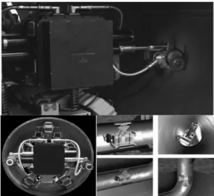
Vision System Applications pipe inspection method is simpler than the existing pipe innovative technology more affordable health inspection techniques, can be

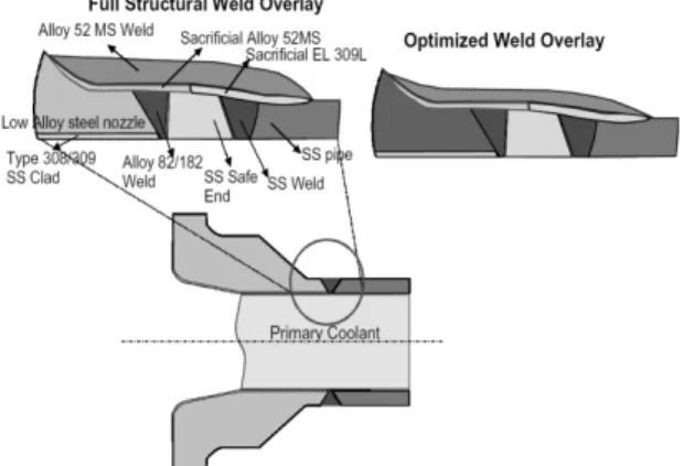
가동 중 원전 압력용기의 관통관 및 노즐배관의 인코넬 600으로 구성된 이종재료 용접부의 경우 PWSCC 손상을 방지하기 위하여 오버레이 다층 용접과정을 통해

Introduction to shape memory effect and shape memory alloy Introduction to electro-active polymer4. Application examples of smart

There are clearly stronger materials, which is understandable given that CrMnFeCoNi is a single-phase material, but the toughness of this high-entropy alloy exceeds that

□ The least-upper-bound property (sometimes called completeness or supremum property) is a fundamental property of the real number system. The least-upper-bound

□ The least-upper-bound property (sometimes called completeness or supremum property) is a fundamental property of the real number system. The least-upper-bound