Progress in Superconductivity and Cryogenics
Vol.16, No.4, (2014), pp.62~65 http://dx.doi.org/10.9714/psac.2014.16.4.062
```
1. INTRODUCTION
A large number of investigations have been applied for high power HTS superconducting applications because of its advantages [1]. One of the key factors is that we should consider the supply of high currents from electric power source to the superconducting magnet, which is kept in high vacuum-stated cryostat, because the HTS devices’
operation needs a supply of high electrical power to them.
It is crucial to eliminate the current lead heat loss that is significantly generated by Joule heating loss and conduction loss. Thus, a partially HTS current lead design has been already proposed for 10 MW-class HTS rotating machine to enhance the current lead thermal characteristics.
Fig. 1 shows a conceptual design of the lead have already announced [2]. It includes a metal part which has the optimal design based on numerical analysis in terms of diameter, material, and it operates from 80 and 300 K.
Another a HTS part is under operation in 30 and 80 K range.
There are HTS tapes enclosed to each side of a square hollow copper support. In an ideal case, we may ignore all Joule heating loss from a HTS partially lead. Thus, the conduction loss is a unique concern, and it is proportional to cross section of metal supports. Consequently, the smaller the cross section is, the less the current lead loss endures. However, we should also follow the commercial standard dimension of metal we intend to use and the fabrication possibility method, as well.
Fig. 1. Former conceptual design of a partially current lead.
This paper continues to optimize the heat loss of a current lead by proposing a new design of HTS part. Then, the transient thermal characteristics of the lead will be also performed. The loss characteristics will be conducted varying to different current ramp rate at 2.5 A/s, 5 A/s, 10 A/s, respectively. Moreover, a sudden discharge is also mentioned in the simulation, in a certain assumption, the fault condition is occurred, and the flux flow losses exposed by DC current is finally calculated by numerical method.
2. NEW CONCEPTUAL DESIGN OF A HTS PARTIALLY CURRENT LEAD
Fig. 2 illustrates the new conceptual design of a HTS partially current lead. It is composed by two side-covers, upper and lower support, which are connected by connection bolts. Then, HTS tapes are occupied inside between the two supports. Because OFHC has a higher thermal conductivity than aluminum, brass, G-10, it absolutely leads to higher conduction loss. However, the
OFHC considerably enhances the thermal stability of the
* Corresponding author: [email protected]
Transient characteristics of current lead losses for the large scale high-temperature superconducting rotating machine
T. D. Lea, J. H. Kima, S. I. Parka, D. J. Kima, H. G. Leeb, Y. S. Yoonc, Y. S. Jod, K. Y. Yoone, and H. M. Kim*, a
a Department of Electrical Engineering, Jeju National University, Jeju, S. Korea
b Department of Materials Science and Engineering, Korea University, Seoul, S. Korea
c Department of Electrical Engineering, Shin Ansan University, Ansan, S. Korea
d Korea Electrotechnology Research Institute, Changwon-si, S. Korea
e Department of Electrical and Electronic Engineering, Yonsei University, Seoul, S. Korea (Received 12 December 2014; revised or reviewed 23 December 2014; accepted 24 December 2014)
Abstract
To minimize most heat loss of current lead for high-temperature superconducting (HTS) rotating machine, the choice of conductor properties and lead geometry - such as length, cross section, and cooling surface area - are one of the various significant factors must be selected. Therefore, an optimal lead for large scale of HTS rotating machine has presented before. Not let up with these trends, this paper continues to improve of diminishing heat loss for HTS part according to different model. It also determines the simplification conditions for an evaluation of the main flux flow loss and eddy current loss transient characteristics during charging and discharging period.
Keywords: Current leads, losses transient characteristic, HTS rotating machine, conduction-cooled lead
T. D. Le, J. H. Kim, S. I. Park, D. J. Kim, H. G. Lee, Y. S. Yoon, Y. S. Jo, K. Y. Yoon, and H. M. Kim
Fig. 2. New conceptual design of a HTS current lead.
TABLEI
SPECIFICATIONS OF THE YBCO CC TAPE(SCS12050).
Characteristics SCS12050
Substrate layer Hastelloy
Stabilizer Copper
Total stabilizer thickness (mm) 0.1
Total thickness (mm) 0.16
Tape width (mm) 12
Ic at 77 K, self field, 1µV/cm (A) 240
Number of tapes 2
Length of lead (mm) 1667
Total cross section of OFHC copper support (mm2) 188 Total conduction heal loss (W) 4.67 conduction-cooled HTS coil because of its superior thermal diffusivity [3]. Therefore, OFHC is used for winding the HTS tapes in the partially HTS leads.
Table I lists the detailed specifications of surround copper stabilizer YBCO coated conductor (CC) used in this study (SuperPower Inc.). It is 12-mm wide and 0.16-mm thick. Our system operating current is 232 A, then we simply use two turns of YBCO tape, it means an average current of each tape is 116 A (at the highest temperature 80 K). This value reaches around two times less than the minimum critical current value of the YBCO CC which is over 240 A (at 77 K, self-field condition). Then the average current value of two turns YBCO tape is sufficient to design the current lead. At this time, the total conduction of partially HTS lead is estimated approximately 4.67 W.
3. LOSS CHARACTERISTICS OF A HTS PARTIALLY CURRENT LEAD
Under the condition DC mode, the heat conduction equation for the conduction-cooled HTS current lead is expressed by Eq. 1 [4]:
( )
+ =0
ff h
h Q
dx A dT T dt k
d (1)
where Ah and kh are cross-section and thermal conductivity of the HTS section, respectively. Qff is flux flow loss in terms of HTS tape exposed by DC current and magnetic field, and it has been carefully conducted by [5].
( )
=
v opt v
opt v
v ff v
ff I
I I
I N
k N aw
Q I exp cosh
4
2 0
ρ 2 (2)
The quantity ρff (1.15x10⁻²⁴ Ω.m) plays the role of flux flow resistivity. While 2a and 2w are HTS thickness and width, respectively. Nv(k) (1.34x10⁸ m-1A-1) is number of vortices per unit length and ampere. Nv0 (76.8x10⁶ m-1A-1) is number of pinning centers per unit length and ampere. Iv
(4.84 A) is pinning strength, and Iopt is operating DC current which depends on duration and various current ramp rate. Fig. 3 shows the maximum flux flow loss is 0.15 W when the current reaches the peak at 116 A at a 46, 24, 12 second, respectively, in considerations of different ramp rate at 2.5 A/s, 5 A/s and 10 A/s.
0 25 50 75 100
0.00 0.04 0.08 0.12 0.16
Flux flow loss (W)
Time (s)
Ramp rate 2.5 A/s Ramp rate 5 A/s Ramp rate 10 A/s
Fig. 3. Flux flow losses varying to current ramp rates.
0 20 40 60 80 100
0 20 40 60 80 100
120 Current
Eddy loss
Time (s)
Current (A)
(a)
0 5 10 15 20
Eddy loss (µW)
0 20 40 60 80 100
0 2500 5000 7500 10000 12500
Eddy current density (A/m2 )
Time (s)
Upper part Lower part
(b)
Fig. 4. Characteristic of ramp rate at 2.5 A/s (a) eddy current loss and (b) eddy current density of upper and lower copper support, respectively.
63
Transient characteristics of current lead losses for the large scale high-temperature superconducting rotating machine
0 10 20 30 40 50
0 25 50 75 100
125 Current rate Eddy current loss
Time (s)
Current (A)
(a)
0 10 20 30 40 50 60
Eddy current loss (µW)
0 5 10 15 20 25 30 35 40 45 50
0 5000 10000 15000 20000
Eddy current density (A/m2)
Time (s)
Upper part Lower part
(b)
Fig. 5. Characteristic of ramp rate at 5 A/s (a) eddy current loss and (b) eddy current density of upper and lower copper support, respectively.
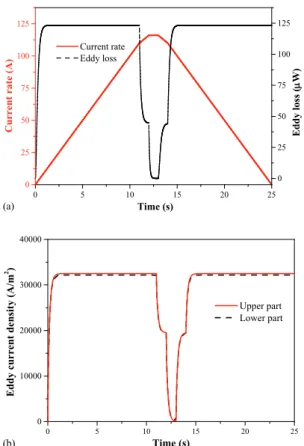
0 5 10 15 20 25
0 25 50 75 100 125
Current rate Eddy loss
Time (s)
Current rate (A)
0 25 50 75 100 125
Eddy loss (µW)
(a)
0 5 10 15 20 25
0 10000 20000 30000 40000
Eddy current density (A/m2)
Time (s)
Upper part Lower part
(b)
Fig. 6. Characteristic of ramp rate at 10 A/s (a) eddy current loss and (b) eddy current density of upper and lower copper support, respectively.
Fig. 4, 5, and 6 are in succession of illustrating the average eddy current loss and eddy current density of copper support varying to different current ramp rate. It is easily seen that the losses is proportional to current ramp.
The faster the ramp rate is, the larger the eddy current loss is deserved. In case of 10 A/s rate, the maximum eddy current is nearly 125 µW, and it decreases to 45 µW, 15 µW for 5 A/s and 2.5 A/s, respectively. Moreover, within ramp rate 2.5 A/s and 5 A/s, respectively, it is seen that the eddy current loss suddenly increases at the last second before the current reaches the peak at 116 A because the current ramp change at the last second. It changed from 2.5 A/s to 3.5 A/s at 45 second and 5 A/s to 6 A/s at 22 second. In contrast, eddy current loss abruptly decreases at 11 second due to ramp rate went down from 10 A/s to 6 A/s in cases of ramp rate 10 A/s.
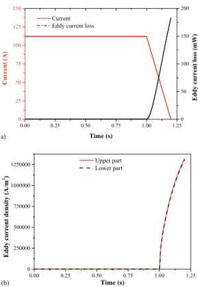
In considerations of fault condition, the equivalent circuit model of a HTS coil is conveniently illustrated in Fig. 7. We assume that the supply current increased to each current level and remained at the level Ipeak 116 A during the steady state operation, then decreased to 0 A. In this case, the current will flow in the two copper stabilizer instead of HTS layer, where L1, L2, and R1, R2 are inductance and resistance of the two copper stabilizers, respectively. Thus, the current ramp rate is conveyed by the Eq. 3 follows:
( )
t Ipeake τtI = − (3) where decay time τ is calculated by the relative between inductance and resistance of copper stabilizer as follows:
l A L R L
τ = = ρ (4) It is estimated that from the peak 116 A, current will drop to 0 A within 0.2 s where resistivity of copper ρ = 5.7x10⁻¹⁰ (Ω.m) and inductance L = 0.185 (μH) calculated by 3D FEA simulation. While l and A are length and cross sectional area of copper stabilizer. Fig. 8 shows the average eddy current loss and eddy current density in cases of fault condition. It is remained 116 A steady state for 1 s, then suddenly discharged to 0 A within 0.2 s. In this case, the maximum eddy current is calculated 175 mW.
Fig. 7. A HTS coil equivalent circuit under fault condition.
64
T. D. Le, J. H. Kim, S. I. Park, D. J. Kim, H. G. Lee, Y. S. Yoon, Y. S. Jo, K. Y. Yoon, and H. M. Kim
0.00 0.25 0.50 0.75 1.00 1.25
0 25 50 75 100 125 150
Current Eddy current loss
Time (s)
Current (A)
0 50 100 150 200
Eddy current loss (mW)
(a)
0.00 0.25 0.50 0.75 1.00 1.25
0 250000 500000 750000 1000000 1250000
Eddy current density (A/m2)
Time (s) Upper part Lower part
(b)
Fig. 8. Characteristic of (a) eddy current loss and (b) eddy current density of upper and lower copper support in cases of fault condition.
0 200 400 600 800 1000 1200 1400 160030
40 50 60 70 80
Temperature (K)
Current lead length (mm) (b)
Fig. 9. Thermal characteristics along the lead (a) surface temperature and (b) temperature distribution along the lead length.
Fig. 10. Eddy current density simulation result of 10 A/s ramp rate at 2.9 second.
4. CONCLUSIONS
The motivation of this paper analyzes the important losses of a current lead. They include eddy current loss of copper support parts be carried by 3D FEA simulation, and flux flow loss of HTS tapes calculated by applying numerical method. All these losses are conducted in terms of various current ramp rate at 10 A/s, 5 A/s and 2.5 A/s, and eddy current calculation, in cases of fault condition, is also proposed at the end. Moreover, the detailed temperature and eddy current density distribution along the lead from 3D FEA simulation are shown in Fig. 9 and 10.
ACKNOWLEDGMENT
This work was supported by the International Collaborative R&D Program of the Korea Institute of Energy Technology Evaluation and Planning (KETEP) grant funded by the Korea government Ministry of Trade, Industry & Energy (20118520020020).
REFERENCES
[1] Difan Zhou, Mitsuru, Motohiro Miki, Brice Felder, Tetsuya Ida and Masahiro Kitan, “An overview of rotating machine systems with high temperature bulk superconductors,” Supercond. Sci. Technol., vol. 25, p. 103001, 2012.
[2] T. D. Le, J. H. Kim, S. I. Park, and H. M. Kim, “Conceptual design of current leads for large scale high temperature superconducting rotating machine,” Progress in Superconductivity and Cryogenics, vol. 16, no. 2, pp. 54-58, 2014.
[3] O. J. Kwon, D. G. Yang, J. Lee, J. B. Song, J. Lee, T. K. Ko, and Haigun Lee, “The effect of bobbin material on the thermal stability of a conduction-cooled HTS racetrack coil,” IEEE Trans. Appl.
Supercond., vol. 24, p. 4602505, 2014.
[4] Yinshun Wang, Fundametal Elements of Applied Superconductivity in Electrical Engineering, 1st ed., John Wiley &
Sons Singapore, 2013, pp. 326-341.
[5] Niclas Schonborg and Sven P. Hornfeldt, “Model of the flux flow losses in a high-temperature superconducting tape exposed to both AC and DC transport currents and magnetic fields,” IEEE Trans.
Appl. Supercond., vol. 11, no. 3, pp. 4078-4085, 2001.
65
![Fig. 1 shows a conceptual design of the lead have already announced [2]. It includes a metal part which has the optimal design based on numerical analysis in terms of diameter, material, and it operates from 80 and 300 K](https://thumb-ap.123doks.com/thumbv2/123dokinfo/5237688.624097/1.892.465.803.654.725/conceptual-announced-includes-numerical-analysis-diameter-material-operates.webp)