A Study on the Development of a Home Mess-Cleanup Robot Using an RFID Tag-Floor
Seung-Woo Kim
1*, Sang-Dae Kim
1, Byung-Ho Kim
1and Hong-Rae Kim
11Department of Electronic Information Engineering, Soonchunhyang University
RFID 환경을 이용한 홈 메스클린업 로봇 개발에 관한 연구
김승우
1*, 김상대
1, 김병호
1, 김홍래
11순천향대학교 전자정보공학과
Abstract An autonomous and automatic home mess-cleanup robot is newly developed in this paper. Thus far, vacuum-cleaners have lightened the burden of household chores but the operational labor that vacuum-cleaners entail has been very severe. Recently, a cleaning robot was commercialized to solve but it also was not successful because it still had the problem of mess-cleanup, which pertained to the clean-up of large trash and the arrangement of newspapers, clothes, etc. Hence, we develop a new home mess-cleanup robot (McBot) to completely overcome this problem. The robot needs the capability for agile navigation and a novel manipulation system for mess-cleanup. The autonomous navigational system has to be controlled for the full scanning of the living room and for the precise tracking of the desired path. It must be also be able to recognize the absolute position and orientation of itself and to distinguish the messed object that is to be cleaned up from obstacles that should merely be avoided. The manipulator, which is not needed in a vacuum-cleaning robot, has the functions of distinguishing the large trash that is to be cleaned from the messed objects that are to be arranged.
It needs to use its discretion with regard to the form of the messed objects and to properly carry these objects to the destination. In particular, in this paper, we describe our approach for achieving accurate localization using RFID for home mess-cleanup robots. Finally, the effectiveness of the developed McBot is confirmed through live tests of the mess-cleanup task.
요 약 본 논문에서는 자율적이며 자동화된 정리정돈 기능을 갖는 홈 메스클린업 로봇(McBot)을 개발한다. 그 동안
진공청소기가 보급되어 집안 청소에 편리성 향상이 이루어졌지만 진공청소기를 운영하는 노동은 인간의 몫이었다. 그
것을 해결하기 위하여 최근에 로봇청소기들이 개발되었으나, 진공 청소하기 이전에 해결해야 하는 신문, 옷가지 등을 정돈하거나 진공흡입하기 어려운 크기의 쓰레기들을 정리하는 것은 여전히 사람이 처리해야 하는 심각한 노동으로 남아 있다. 이러한 이유로 본격적인 청소로봇 시장이 아직 형성되지 못하고 있다. 그래서 본 논문에서는 가정에서의 정리정돈 문제를 해결할 수 있는 소위 홈 메스클린업 로봇을 개발하고 새로운 디자인 방법과 제어 기법 그리고 자기
위치 인식 알고리즘을 제안한다. 홈 메스클린업 로봇은 정리정돈을 위하여 쾌속 네비게이션과 정교한 매니퓰레이션
기능을 필요로 한다. 본 논문에서는 자율적인 네비게이션 기능으로 장애물을 회피하여 원하는 목적지까지 고속으로
이동할 수 있는 휠 기반의 이동로봇을 개발한다. 또한 정리정돈 작업을 위한 정교한 매니플레이션 기능으로 6 자유도 를 갖는 로봇 팔과 리프트 등의 보조장치들을 개발하며, 그것들이 정밀 제어될 수 있는 새로운 알고리즘을 제시한다. 특히 홈 메스클린업 로봇의 탐색 시스템은 지금까지의 청소로봇들과는 달리 일정한 패턴이나 벽면을 따라 움직이는 방식이 아닌 실질적인 실내 구조의 파악과 잡은 물체를 원래의 위치로 이동시키거나 정돈 장소까지 이동하기 위한 절대 좌표 형태의 자기 위치 인식 기능이 필요하다. 그러므로 본 논문에서는 자신의 절대좌표 인식 및 물체인식을 위
하여 RFID 태그들을 이용한 자기위치 인식 시스템을 개발한다. 마지막으로 본 논문에서 설계된 홈 메스클린업 로봇
이 RFID 환경에서 정리정돈작업을 수행하는 실제 실험을 통하여 좋은 성능을 검증한다.
Key Words : Mess-Cleanup; Home Service Robot; Navigation System; Manipulation; Self-localization; RFID tags
This research was financially supported by the Ministry of Education, Science Technology (MEST) and Korea Institute for Advancement of Technology (KIAT) through the Human Resource Training Project for Regional Innovation.
*Corresponding Author : Kim, Seung-Woo([email protected])
Received January 12, 2010 Revised February 16, 2010 Accepted February 24, 2010
1. Introduction
Home Service Robots, a kind of personal robot for work, amusement, and homeschooling, are widely studied these days. The cleaning robot is a product of home service robots. The cleaning robot is also an electric home appliance, which is developed on the basis of the wheel-based mobile robot in the same method as a vehicle robot for factory automation and a guidance robot[1, 2]. The vacuum-cleaner was developed in the 1950s to aid in the manual cleaning of houses, which had been the most dominant household chore. It has lightened the burden of household chores but the operational labor involved in vacuum-cleaners has been very severe.
Recently, a cleaning robot was commercialized to perfectly address the issue of labor in the cleaning of houses but it also was not successful because it still had a problem in mess-cleanup, namely, the clean-up of large trash and the arrangement of newspapers, clothes, etc. The cleaning robot just vacuums dust and small trash and has no capability for arranging and taking away large trash prior to the automatic vacuum-cleaning. For this reason, the market for the cleaning robot has not yet been built up actively. Hence, we need a design method and technical algorithm for a new automatic machine to solve the problem of mess-cleanup in houses. In this paper, a home Mess-Cleanup Robot(McBot), which has the practical functionality of automatic mess-cleanup, is developed.
McBot does not work in fixed tasks as do industrial robots because it is together with humans in the same indoor space but has to work in much more flexible and diverse environments[3]. Therefore, McBot needs the capability for agile navigation and a novel manipulation system for mess-cleanup. The autonomous navigational system has to be controlled for the fol scannavigatithe living room and for the precise tracking atithe desired path. It must bel maniable to recognize the absolute position and orientation atiitself and to distinguish the messed object that is to be cleaned up from obstacles that should merely bel voided. One atithe most fundamental pieces atiinformation that is needed is the positional (localization)iinformation atithe object. The use d forser and ue rd upic sensors is common f be cleapurpose but e pre sensors canne rdense objects through obstacles
(viz.,ithe line-d -atih rct. The). Recenosi,ithere h veOne ata falizttempts tniapply RFID in localization[4,i5]. RFID does not am fer from the line-d -atih rct. The, and its object ID can be trivially retrieved. HowevecomRFID has eapurpose with triangulation, sors cis the most common localizationeeded iqtioto be adopted iata ubiqtitous sensor network retrieved.to work,ithe distance betwe ata sensor les (vizdensed object needs to be ac brately mHowured.
Howevecomtt ti’smRFID technology does not ct.vide enough aysuracy iatdistance med urementic sensemRFID-sensing literature, nsembest resue manifaredields anl verage ert.r d f0i77 faet in co.rdinate detection. It is not aysurate enough f berely bnavigation[5]. Ert.rs in RFtdistance med urement aysount for such inaysuraciupicTherefore, isensors is comwe suggest localiatiiatiimplementd merely blocalizationeusing RFIDicThorse f ay is as irely bMcBot dct. Thmentic sensih rct. Thment, we place an RFID reader onto McBot and prepare a tag-floor. A tag-floor is a floor that is installed with RFID tags, each of which possesses coordinate information of itself. Under such a setting, McBot may acquire accurate coordinates during navigation because the localization error does not depend on the distance between the reader and the tag. The manipulator, which is not needed in the vacuum-cleaning robot, has the capabilities of: distinguishing large trash that is to be cleaned from messed objects that are to be arranged; using its discretion in relation to the form of messed objects; and to properly carry these objects to the destination for arranging them. Also, for McBot to accomplish the mess-cleanup, object information pertaining to the computing is important. In this paper, a robot that incorporates all the above features is optimally implemented.
2. Design of McBot
In this section, we develop a home mess-cleanup robot, McBot. The appearance of the implemented McBot is shown in Fig. 1. The mechanical body is fabricated by the RP (Rapid Prototype) machine. The developed parts are also explained in Fig. 1.
[Fig. 1] Appearance of the Implemented Mcbot.
The agile-navigation system of McBot consists of two servomotors, one steering wheel, and two driving wheels.
They are stably designed in spite of high-speed movement and are flexibly made in the driving mechanism. The electric motor is connected to wheels by the belt. The mechanical suspension system is designed for going past the doorsill in houses. It is implemented by a mechanical hinge system. The steering wheel is designed through a pith and roller for the purpose of smooth navigation. The lifting support system is stably controlled by two servomotors to upload the messed object. It is precisely designed by the use of steel wire and an LM (linear motion) guide.
The novel manipulation system consists of two arms and grippers for picking up the messed object and to transport the object and set it down on the destination spot. The articulated arm is designed to have 6-DOF (Degrees of Freedom).
McBot accomplishes self-localization by the optimization of the RFID tag-floor and object recognition by the fusion algorithm of RFID and the conventional sensors. This paper focuses on the localization and navigation of McBot in an academic standard, which consists of two main controllers: the Trajectory Controller and the Self-Localization Controller. The Trajectory Controller is responsible for wheel-based navigation. The Self-Localization Controller provides coordinate information of the moving McBot. For robotic movement, a pair of navigational wheels is installed. With the coordinate information that is acquired from the Self-Localization Controller, the Trajectory Controller refines McBot movements to achieve better navigation.
We let McBot know of its own coordinates through RFID sensing. We place a RFID reader onto McBot. On the indoor floor, we place multiple RFID tags and associate
each tag (tag ID) with a coordinate. During an actual navigation, as McBot detects a tag, its coordinates are fed to the trajectory controller for further control of the navigation.
There may be many sensible ways of placing RFID tags on the floor. Nevertheless, it is practical to prepare tiles of the same kind and assemble them to produce a navigational floor. The simplest way of arranging RFID tags on a tile is to place four tags in a square (“square”), as in Fig. 2(a). Another way might be the
“parallelogram,” which is suggested in Fig. 2(b).
[Fig. 2] Possible Misses of Tag Detection.
It is suggested that with the pattern in Fig. 2(a), there is a greater likelihood of missing tag detections[4].
However, as we can see from Figs. 2(a) and 2(b), the likelihoods of missing tags are about the same in both cases. Therefore, we suggest the “tilted-square” pattern, as in Fig. 2(c). This pattern seems to offer the lowest likelihood of missing tag detections during navigation. For tag-floor navigation, the more tags we place on the floor, the higher will be the likelihood of encountering a tag. In this case, we can more often compensate for the error that accumulates through wheel-based navigation. However, it would be desirable to place only a minimum number of tags on the floor.
3. Control of McBot
The control of McBot is divided into navigation, manipulation, and sensing. The main controller is implemented by a high-speed micro processor. A wide variety of IO devices are designed by an optimum-seeking IO-Mapped method.
3.1 Navigational Controller
We know that the navigational system consists of two driving wheels and motors with encoders and reduction gears. Actually, the positions and velocities of the wheels are precisely controlled.
VR=rωR, VL=rωL (1) ω=VR-VL
L =rωR-ωL
L (2)
v=VR+VL
2 =γωR+ωL
2 (3)
Where, ωR,ωL are the angular velocities of wheels.
v : Linear velocity of McBot ω : Angular velocity of McBot r : Radius of the wheel
L : Distance between two wheels.
[Fig. 3] McBot Platform
First, we have to comprehend the kinematic model of two motor-based wheels, of which Fig. 3 displays a schematic diagram. We can derive a kinematical model from Fig. 3. McBot’s speed at the point of contact of the wheel with the floor under the non-slipping condition is given in Eq. (1). It is easy to verify te non-e relationship between
and can be expressed as the kinematical formula, (3) [7].
(4)
Two postures, the reference posture, Pr=[xr yrθr]T,
and the current posture, Pc=[Xc Ycθc]T, as shown in Fig. 3, are used in the navigational control of McBot. An error posture, Pe, can be derived and is given in Eq. (4) [7].
(5)
In the literature, the nonholonomic tracking probleckis sicplified by neglecting the vehicle dynamics and considering only the steering system. To compute the control inputs, iuts, assumed that there s, ‘perfect velociuy tracking’. There are three problecscs and cs, approach.
First,d by nerfect velociuy tracking assumption doe, not hold in pracache. Sectem, disturbance, are sgnored.
Finally, complets, nowledgs,hicle ddynamics i, nplied . To osumcomed by nroblec,cse npli an gleegration hicle dnonholonomic approach controllonland the dynamics hicle dmobile robot. Therefore, the control methom hic‘Computed Torquecs andPID’ i, used in thi, paper[3, 8].
3.2 Manipulation Controller
We know that McBot has two articulated robotic arms, which the conventional cleaning robots have never used.
That is why it has to capture and release the messed objects. This job requires intelligence; hence, McBot needs a novel controller. Each robotic arm is made up of six joints. They are independently controlled. Table 1 shows the link parameters of Denavit-Hartenberg.
Joint i Θ α A d
1 Θ1 -90 12.2 53
2 Θ2 90 0 0
3 Θ3 -90 0 217.6
4 Θ4 90 0 0
5 Θ5 -90 0 230.7
6 Θ6 90 78.82 0
[Table 1] Link Parameters for McBot’s Arm
Θ : Joint angle α : Link twist angle A : Link Length d : Joint distance
Using the Denavit- Hartenberg notation, we can express the position and orientation of the end-effector, as a function of the joint displacements. We solve the problem of moving the end-effector of McBot’s arm to a specified position. For precise control of the manipulator, we need to find the joint displacements that lead the end-effector to the specified position through the derived equations from the specified link parameter. The joints are independently and precisely controlled by the point-to-point method.
3.3 Sensor Controller
In order to determine efficient tag-granularities and tag-arrangements for the tag-floor, we developed a simulation program. We defined a measure of the error in navigation and used it to analyze the effectiveness of the tag-floor. Since we are considering McBot’s movement under no obstacles the most important factor of performance is the time the robot takes to travel from a given departure point to a given destination point. This is the sum of (i) the times for straight-line movement as the robot traverses each successive point and (ii) the total time for the robot to adjust its posture at the various tags.
Further, the movement depends on the arrangement of tags on the floor. Therefore, we define the time for McBot’s navigation as:
(6)Where Te(xs, xd) : Navigational time from xs to xd under the floor-arrangement
tm(xa, xb) : Time for straight-line movement from xa to x
b
tr(xa, xb) : Time for posture adjustment from x
a for x
b
xs, x0 : Departing points xd, xn : Destination points
x1...xn-1: Locations of successive tags encountered during navigation
By subtracting the total time for straight-line movements between the departure and the destination points from Eq. (6) and by normalizing this value by the total time for straight-line movements, we define the
relative navigational error, REe(xs, xd), for comparing the effectiveness of different tag arrangements and granularities[9].
(7)
We can observe that there is an important role of sensor controllers in distinguishing the messed object from the fixed obstacle and the object to be arranged from the large trash. McBot accomplishes the former task by the fusion of RFID and gyro sensors. An RFID reader is fitted on the back of the lifting support and tags are fitted on the back of the wooden tile floor. The angle of the wheel is detected from gyro sensors every second for compensating for the localization. The current positions of McBot and the object are derived from the data through basic equations. Also, McBot achieves the job of recognizing the size and form of the messed object by the fusion algorithm of RFID and stereo-vision.
4. Results and Considerations
As noted earlier, in this paper, we develop a new home mess-cleanup robot, McBot. The dimensions of Mcbot are 356 x 446 x 585. For agile navigation, two motor-based wheels are implemented in a large size, viz., of radius 57.
For novel manipulation, two 6-DOF manipulators are designed for the lengths of 217.6, 230.7, and 78.82 for the brachium, forearm, and hand, respectively. The height of the lift is set to 300. A robot that includes all the above features is optimally implemented. For convenience in experimentation, the floor of the living room is of the size, 2400 x 4800.
(8)For McBot, we assume the mechanical parameters as
, , , , and
; thus, the dynamic equation can be perfectly determined [3, 8].
The dynamic equation for the computed-torque method is expressed in matrix form as Eq. (8). We tuned the simplified PID controller so that the coefficients are Kp=15.3, KI=0.2 and KD=3.2 for the right wheel and Kp=14.6, KI=0.25 and KD=3.9 for the left wheel The controlled input vector,
, and the torque vector,
, wereprecisely computed through the PID gain value and the dynamic equation, viz., (8).
The simulation program measures the relative effectiveness of the navigation. In this program, we use various parameters to better reflect real-world navigation.
The major parameters a user can specify are as follows.
Tag patterns. “Square”, “Parallelogram” or “Tilted-square”
can be chosen.
Tag granularities. Four tags per tile. Hence, the tile size determines the granularity.
Read-ranges of the tag and the reader. There are many types of tag and reader. Therefore, we make this parameter flexible.
Others. These refer to the velocity, posture adjustment time, and angular wheel error.
By using the definition of in Equation (7) and varying the patterns and granularities of the tags, we analyzed McBot’s navigational performance through simulation. We used 50,000 randomly generated departure-destination pairs. We accumulated values for each of the three floor patterns and used the mean REe values for the performance comparison. Among the simulation parameters, some are fixed to reflect real-world situations. Table 2 summarizes the fixed values used.
Parameters Values
Floor Size 1000cm × 1000cm Velocity (Straight, Rotation) 10.0cm/sec, 2.0cm/sec
Minimum Path Distance 400 cm Angular Error Rate ±
[Table 2] Fixed Simulation Parameters.
In order to determine how many tags are sufficient to generate efficient navigational performance, we find the correlation between navigational performance and tag granularities. We differentiate tag granularities by adjusting the read range and the tag interval. The read range is determined by the maximum distance between the centers of a tag and the reader. The tag interval is the distance between the center of one tag and its closest tag on the floor.
Tag Granularity. We notice that according to the simulation results, there exists an optimal tag interval where becomes minimal, regardless of the tag arrangement patterns. By performing simulations on various read ranges and extracting those minimal
values, we conclude that there exists an optimal relationship between the read range and the tag interval (tag granularity). Table 3 summaries the optimal results that are obtained from various read-ranges. It shows that by maintaining the interval at about four times the range (about 4:1 ratio between the tag interval and the read range), we attain the minimal navigational errors in terms of .
Read Range
Optimal Interval
Relative error (RE) in Percent
6 cm 28 cm (T) 36.94% (S) 40.36% (P) 39.82%
8 cm 33 cm (T) 32.51% (S) 35.97% (P) 35.59%
10 cm 41 cm (T) 29.75% (S) 32.76% (P) 33.08%
12 cm 45 cm (T) 27.53% (S) 30.58% (P) 30.21%
14 cm 53 cm (T) 26.01% (S) 28.35% (P) 29.32%
[Table 3] Optimal Tag Intervals and RE Values
(T: Tilted-Square, S: Square, P: Parallelogram)
Tag Arrangement Pattern. Under the optimal tag granularities, we compare the three tag arrangement patterns in terms of performance by consulting the RE column in Table 3. In all cases, the “tilted-square”
arrangement produces the best performance with regard to the relative effectiveness. From the results, we conclude that the “tilted-square” pattern suggested in this study produces the best efficiency for tag-floor navigation.
The RFID tags, which are the most important sensors in this paper, are optimally placed underneath the living-room floor. 128 RFID tags are installed by the
“tilted square” method.
[Fig. 4] Living-Room Floor Equipped by RFID Tags.
This layout is shown in Fig. 4. The messed objects are a bottle of water, a paper that corresponds to large trash, and a CD case.
Fig. 5 shows the result of steady-state control for forward-position travel of McBot.
[Fig. 5] Position Control of Mcbot
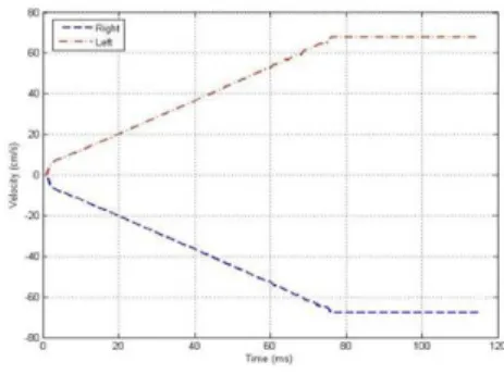
[Fig. 6] Velocity Control (left turn)
We can see that the positional control is perfectly stable. Figs. 6 and 7 show the result of velocity control for the left/right turns. In this experiment, we can confirm that the robot is agilely tracking the desired command for efficient navigation.
[Fig. 7] Velocity Control (right turn)
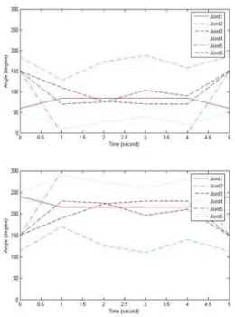
We know that the novel manipulation job is very important in this study. That is why McBot has to capture and release the messed objects. Hence, we implement two robotic articulated arms that are designed through six joints. The joints are independently and precisely controlled by the lookup-table method. Fig. 8 shows the control input signals of the right and left arm that captures the messed objects. From the figure, we can know that the arm is agilely controlled and cooperatively works with the other arm. Fig. 9 shows the control input signals of the right and left arm that releases the object.
From the figures, we can conclude that the arm is agilely controlled and cooperatively works with the other arm for the proper capture and release of the target object.
[Fig. 8] Control Signals of the Robotic Arm (capture)
[Fig. 9] Control Signals of the Robotic Arm (release)
We have three kinds of object on the floor of the living room. After all, three kinds of mess-cleanup job are achieved in this experiment.
[Fig. 10] Image Clips for Mcbot's Live Test
Fig. 10 shows image clips of McBot’s accomplishment of the mess-cleanup. From the figure, through a live test of the mess-cleanup task, we can conclude that the developed McBot attains a good level of performance
5. Conclusion
We develop a new home mess-cleanup robot, McBot, to perfectly overcome the problems of the conventional cleaning robots indoor. It consists of components for navigation, manipulation, and sensing. To get the robot to accomplish the mess-cleanup task in the house and to work well with humans in the same space, we develop a wheel-based navigational system for agile tracking, 6-DOF manipulators that are precisely controlled, and a sensor-fusion algorithm that confers intelligence. The autonomous navigation system is controlled for the full scanning of the living room and for the precise tracking of the desired path. For the implementation of the self-localization feature of McBot, we used RFID technology. Unlike other conventional sensors, RFID readers do not suffer from the line-of-sight problem;
hence, a better implementation of McBot’s navigation is possible.
References
[1] Breazeal (Ferrell), C. “A motivational system f regulating human-robot interaction” In Proceedings of AAAI 98, pp 54-62, 1998.
[2] Funge, J., Tu, X., Terzopoulos, D. “Cognitive Modeling:
Knowledge, Reasoning and Planning for Intelligent Characters” In Proceedings of SIGGRAPH 99, pp 29-38, 1999.
[3] Gabriel Ramírez, Saïd Zeghloul. “A New Local Path Planner for Nonholonomic Mobile Robot Navigation in Cluttered Environments” Proceeding of the IEEE International Conference Robotics and Automation, pp 2058-2063, 2000.
[4] Kantor, G., Singh, S. “Preliminary Results in Range-Only Localization and Mapping.” Proceedings of the IEEE Conference on Robotics and Automation, pp 1818-1823, 2002.
[5] Hahnel, D., Burgard, W., Fox, D., Fishkin, K., Philipose, M. “Mapping and Localization with RFID Technology”
Robotics and Automation, 2004. Proceedings. ICRA '04.
2004 IEEE International Conference on, Vol 1, pp 1015-1020, 2004.
[6] Itiro Siio. “User Position Detection using RFID Tags", Technical Report Proceedings of Japanese Information Processing Society, 00-HI-88, pp 45-50, 2000.
[7] Kawamura, K. Pack, R. T., Bishay, M., Iskarous, M.
“Design philosophy for service robots” Journal of Robotics and Autonomous Systems, 18, pp 109-116, 1996.
[8] Maeyama, S., Yuta, S., Hararda, A. “Experiments on a Remote Appreciation Robot in an Art Museum”
Proceedings of IROS 2000, 2000, pp 1008-1013, 2000.
[9] Hyun-Koo Cha, Seungwoo Kim. “A Study on Implementation of Ubiquitous Home Mess-Cleanup Robot” Journal of Control, Automation, and Systems Engineering, Vol. 11, No 12, pp 1011-1019, 2005.
[10] Baker, R. Human Navigation and the Sixth Sense, New York , Simon and Schuster, 1981
[11] Dong Sung Kim, Hyun Chul Lee, Wook Hyun Kwon.
“Geometric Kinematics Modeling of Omni-directional Autonomous Mobile Robot and Its Applications”
Proceedings of the IEEE International Conference Robotics and Automation, 2000, pp 2033-2038, 2000.
[12] Hardt, V. D., Arnould, P., Wolf, D., Dufaut, M.
“Method of mobile robot localisation by fusion of odometric and magnetometric data” International Journal of Advanced Manufacturing Technology, vol 9 no. 1, pp65-69, 1994.
Seung-Woo Kim
[Regular member]• Feb. 1987 : Yonsei Univ., Dept. of Electronic Eng., Bachelor
• Feb. 1994 : Yonsei Univ., Dept.
of Electronic Eng., MS
• Feb. 1994 : Yonsei Univ., Dept.
of Electronic Eng., PhD
• 1998 ∼ 1999 : CWRU Post-Doctoral Program in Robotics
• Jan. 1987 ∼ Aug. 1989 : Samsung Advanced Institute of Technology, Researcher
• Feb. 1994 ∼ current : Soonchunhyang Univ., Dept. of Electrical Information Eng., Professor
<Research Interests>
Service Robot, Mobile Robot, Entertainment Robot, Fuzzy Control
Sang-Dae Kim
[Regular member]• Feb. 2009 : Soonchunhyang Univ., Electrical Electronic Eng., Bachelor
• Feb. 2009 ~ current :
Soonchunhyang Univ., Dept. of Electrical Robotics Eng., Course of MS
<Research Interests>
Mobile Robot, Service Robot
Byung-Ho Kim
[Regular member]• Feb. 2007 : Soonchunhyang Univ., Div. Information Technology Eng., Bachelor
• Feb. 2009 : Soonchunhyang Univ., Dept. of Electrical Robotics Eng., MS
• Feb. 2009 ~ current :
Soonchunhyang Univ., Dept. of Electrical Robotics Eng., Course of PhD
<Research Interests>
State Estimation, Smart Grid, State Estimation and Observation
Hong-Rae Kim
[Regular member]• Feb. 1986 : Yonsei Univ., Dept. of Electrical Eng., Bachelor
• Feb. 1989 : Yonsei Univ., Dept.
of Electrical Eng., MS
• Feb. 1995 : Texas A&M Univ., Dept. of Electrical Eng., PhD
• Feb. 1995 ∼ current :
Soonchunhyang Univ., Dept. of Electrical Information Eng., Professor
<Research Interests>
Power System, Smart Grid, State Estimation