기록부위 변화가 두피 체성감각유발전위에 미치는 영향
부산대학교 의과대학 재활의학교실, 고려대학교 의과대학 안산병원 재활의학과*
박병규∙이종언∙이상헌*
– Abstract –
Changes of Scalp-Recorded Somatosensory Evoked Potentials Related to Recording Methods
Byung Kyu Park, M.D., Jong-Eon Lee, M.D., Sangheon Lee, M.D.*
Department of Rehabilitation Medicine, Pusan National University College of Medicine Department of Rehabilitation Medicine, Korea University Ansan Hospital*
Objectives
: To establish the distribution of near-field potential (NFP) and far-field potential (FFP) of somatosensory evoked potentials (SEPs) recorded at the scalp with different recording methods.
Methods
: SEPs elicited by stimulation of the right median nerve were recorded in 30 healthy subjects.
Thin steel needle electrodes were placed subcutaneously with 5 different recording montages; C3´-Fz;
C3´-left upper extremity (LUE); C4´-Fz; C4´-LUE; Fz-LUE. We compared the SEPs recorded with each recording montage by measuring N1 and P1 potentials occurring over 15 msec after stimulus.
Results
: N1 and P1 latencies of the responses at C3´ and C4´ were not significantly different each other and not changed with recording method. However, N1-P1 amplitude was considerably affected by record- ing montage. With comparison of potentials recorded at Fz and C3´, N1 latency of SEPs at C3´ was not different from P1 latency at Fz.
Conclusion
: Subcortical FFPs and cortical NFPs would be distributed in the region of C3´, however, only FFPs would be recorded at C4´. In addition, distant NFPs and FFPs are represented at Fz. With cephalic bipolar recording montage, N1 potential would be considered as a summation of N1 at C3´ and P1 at Fz.
Key Words
: Somatosensory evoked potentials, Scalp, Near-field potential, Far-field potential
부산대학교 의과대학 재활의학교실
Address reprint requests to Byung Kyu Park, M.D.
Department of Rehabilitation Medicine, College of Medicine, Pusan National University, #1-10 Ami-dong, Seo-ku, Pusan, 602-739, Korea
Tel : 82-51-240-7484, Fax : 82-51-247-7485, e-mail : [email protected]
서 론
체성감각유발전위는 말초신경에서 대뇌피질까지의
체성감각계의 기능을 평가하기 위해 시행되고 있고 근 접부위 유발전위(near-field potential)와 원범위 전위(far-
field potential)로 구성된다.
1근접부위 유발전위는 기록 부위간의 거리에 따라 변하지만 원범위 전위는 동일한 조건의 volume 전도매체 내에서 거리와 관계없이 양성또는 음성의 극성으로 일정하게 발현되는 특성을 띄게 된다.2-4정중신경을 자극하여 두부에서 기록하였을 경 우, 체성감각 피질에서 유발되는 전위는 근접부위 유발 전위로 생각되지만 시상에서 유발되는 전위는 원범위 전위로 알려져 있다.5-7
기록방법으로는 두부 내의 neural generator에 가까운 부위에 활성전극을 부착하고 참고전극을 두부에 부착 하는 쌍극기록 방식(bipolar recording montage)과 참고전 극을 쇄골, 상완, 완관절 등 두부 이외의 부위에 부착하 는 참고기록 방식(referential recording montage)이 이용 되고 있다.8-10쌍극기록 방식은 원범위 전위 및 잡음을 제 거하여 근접부위 유발전위를 용이하게 평가할 수 있고 참고기록 방식으로는 원범위 전위까지 기록할 수 있는 장점이 있다. 상지신경 자극에 의한 체성감각유발전위 의 두피 내 기록 부위로 널리 이용되는 방법은 쌍극기록 방식으로 체성감각피질에서 유발되는 근접부위 유발전 위를 평가할 수 있다.
본 연구에서는 기록부위 및 방법에 따른 단잠시 체성 감각유발전위(short latency SEP)의 변화를 조사하여 근 접부위 유발전위 및 원범위 전위의 특성을 관찰하고, 통 상적인 두부 쌍극기록(cephalic bipolar recording) 방식으 로 기록되는 체성감각유발전위가 근접부위 유발전위와 원범위 전위가 통합되거나 상쇄되는 과정을 분석하고 자 한다.
연구 대상 및 방법
25세에서 34세까지(평균 25.8±3.1세)의 건강한 성인 30명으로 남자 29명, 여자 1명이었고 신장은 평균 174.3
±4.2cm(166cm~184cm)이었다.
검사실의 온도를 22~24℃로 일정하게 유지하면서
Counterpoint MK II (Dantec, Denmark) 근전도기기를 사
용하였고 우측 정중신경을 자극하여 유발된 체성감각 유발전위를 기록하였다. 자극의 강도는 단무지의 경미 한 움직임이 육안으로 보이기 시작하는 정도로 하였고, 빈도는 초당 1.5회, 자극지속시간은 0.2msec, 주파수 폭 은 5Hz~2KHz, 기록속도는 5msec/division, 기록감응도는5μV/division으로 설정하였다. 기록전극은 1cm 길이의
표피 침전극을 이용하여 국제뇌파 10-20 시스템에 입각 한 C3´와 C4´지점과 Fz 지점에 5가지 방법으로 부착하 였다. 즉, C3´와 C4´ 지점에서는 쌍극기록 방식(C3´-Fz 및 C4´-Fz)과 참고기록 방식(C3´-좌상완 및 C4´-좌상완) 으로 부착하였고 Fz 지점에서는 참고기록 방식(Fz-좌상 완)만으로 설정하였다.200회 반복 자극 후 통합∙평균하는 과정을 2회 시행
하여 얻어진 체성감각유발전위에서 15msec 이후에 유발 된 N1과 P1 잠시와 N1-P1 진폭을 조사하여 기록방법과기록부위에 따른 변화를 분석하였다.9,11통계학적인 검 정을 위하여 마이크로소프트 윈도우용 SPSS 풀그림
(Release 7.5.2K, 표준버전)에 의한 unpaired t-test를 시행
하였고, p 값이 0.01 미만일 경우를 통계학적으로 유의한 것으로 간주하였다.결 과
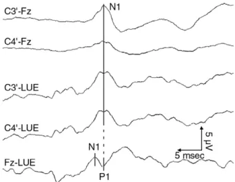
우측 정중신경을 자극하여 쌍극 또는 참고기록 방식 으로 C3´, C4´, Fz 지점에서 체성감각유발전위를 기록하 였다(Fig. 1). C3´ 지점에서 기록된 체성감각유발전위는 쌍극기록의 경우, N1 잠시가 평균 19.2msec, P1 잠시가
25.0msec, N1-P1 진폭이 6.16μV이었고 참고기록의 경우
에는 N1 잠시가 19.1msec, P1 잠시가 23.4msec, N1-P1 진 폭이 3.98μV이었다(Table 1). C4´ 지점에서의 전위는 쌍 극기록의 경우, N1 잠시가 평균 19.5msec, P1 잠시가24.9msec, N1-P1 진폭이 2.80μV이었고 참고기록의 경우
에는 N1 잠시가 19.2msec, P1 잠시가 22.7msec, N1-P1 진 폭이 3.16μV이었다(Table 1). Fz 지점에서 참고기록 방식 으로 기록된 전위의 경우 N1 잠시는 17.1msec이었고 P1 잠시가 20.4msec, N1-P1 진폭이 1.93μV이었다(Table 1).C3´와 C4´ 지점에서 각각 기록된 체성감각유발전위를
비교하면, N1 및 P1 잠시는 기록방법에 관계없이 C3´ 및C4´에서 서로 유사하였고 각 기록방법에 의한 N1-P1 진
폭은 C4´ 지점에서 유의하게 작았다(Table 2). 쌍극기록 과 참고기록 방식에 따라 비교하였을 경우에도, 각 전위 의 N1 및 P1 잠시는 기록부위와 관계없이 유의한 차이Fig. 1. Representative pattern of somatosensory evoked poten- tials elicited by stimulation of right median nerve and recorded with different recording methods. With non- cephalic referential recording montage, reference elec- trode was placed subcutaneously at the proximal part of left upper extremity (LUE).
가 없었고 N1-P1 진폭은 C3´ 지점에서 참고기록 방법에 의한 경우에서만 유의하게 작았다(Table 3). 참고기록 방법으로 Fz 지점에서 기록된 N1 및 P1 잠시는 C3´ 지점 에서보다 유의하게 단축되었고 N1-P1 진폭은 C3´ 지점 에서보다 의미 있게 작았다(Table 4). 그리고 Fz 지점에 서의 P1 잠시는 C3´ 지점에서의 N1 잠시와 유의한 차이 가 없었다.
고 찰
두피에 기록되는 체성감각유발전위 검사는 쌍극기록 방식에 의하여 통상적으로 시행되며 N1에 해당되는 N1
(N20) 전위가 가장 유용하다고 알려져 있다.
1,10이러한 검사방법으로 상지를 자극하여 체성감각유발전위를 검 사하는 경우 기록전극이 자극부위와 동측의 두피에 삽 입되었을 경우에도 N1과 P1 전위를 뚜렷하게 관찰할 수 있기 때문에 진단적 오류를 범할 가능성이 있다고 생각 된다. 이는 원범위 전위와 반대측 기록부위에서 유발된 근접부위 유발전위가 합쳐져서 자극부위와 동측인 경 우에도 반대측에서 기록된 전위와 유사한 형태로 유발 될 수 있기 때문으로 생각된다.정중신경 자극으로 의한 C3 또는 C4에서 기록된 체성
감각유발전위 중 원범위 전위는, 상완신경총에서 유발 되는 P9 전위, 후근에서의 P11, 내측모대 부위의 P13 또 는 P14와 함께 시상 또는 뇌간 근처에서 기시한다고 생 각되는 N18 전위 등으로 구성된다.1근접부위 유발전위 로는 롤란도구후열에서 유발되는 N20, 운동영역에서의
P22, 두정엽 피질에서의 P27 등이 보고된 바 있다.
1본 연구에서 자극부위와 동측에서 기록된 전위의 경 우 기록방식에 관계없이 반대측에서 기록된 전위에 비 하여 잠시는 유사하였으나 진폭은 작았다. 이러한 결과 로, 자극 반대측 두피에서는 롤란도구후열에서 유발되 는 근접부위 유발전위(N20)와 시상 근처에서 유발되는 원범위 전위(N18)가 함께 유발되지만 자극 동측의 두피 에서는 원범위 전위만 기록된다고 생각할 수 있다. 쌍극 기록과 참고기록 방식에 따라 비교하였을 경우, 각 전위 의 N1 및 P1 잠시는 유사하였고 진폭은 자극 반대측에 서 참고기록 방법으로 기록된 경우에서만 작았다. 자극 반대측에서 기록된 N1 전위가 쌍극기록의 경우에서 큰 이유는 활성전극에서 기록되는 근접부위 유발전위
(N20)가 참고전극에서의 유사한 잠시의 양성편향 전위
의 역상과 합쳐져 증폭되기 때문으로 생각된다. 자극 동 측에서 기록될 경우에는 이러한 전위의 증폭 효과가 없 으므로 기록방법에 따른 전위의 차이가 없었다고 생각 된다.전두엽 부위에서 측정된 전위는 반대측 대뇌에서 발 생된 전위가 주위로 퍼지면서 기록되는 것으로 알려져 Table 1. Changes of Waveforms with Different Methods of
Recording
Recording N1 latency (ms) P1 latency (ms) Amplitude (µV)
C3´-Fz 19.2±0.9 25.0±3.5 6.16±3.4
C3´-LUE1) 19.1±1.1 23.4±2.5 3.98±2.3
C4´-Fz 19.5±1.1 24.9±2.7 2.80±2.1
C4´-LUE 19.2±1.5 22.7±2.1 3.16±1.6
Fz-LUE 17.1±1.3 20.4±2.4 1.93±0.7
1. LUE: Left upper extremity
Table 4. Comparison of Potentials Recorded at Fz and C3´
Recording N1 latency (ms) P1 latency (ms) Amplitude (µV) Fz-LUE1) 17.1±1.3 20.4±2.4* 1.93±0.7 C3´-LUE 19.1±1.1 23.4±2.5* 3.98±2.3
p-Value 0.0000015 0.00015 0.0051
1. LUE: Left upper extremity
*: p>0.05 by unpaired t-test with comparing to N1 latency of the potential recorded at C3´
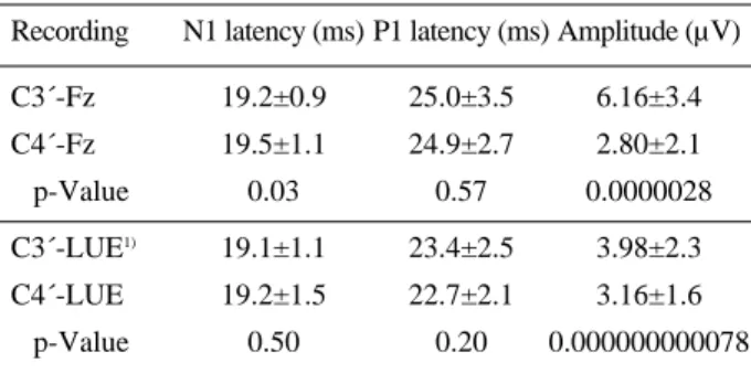
Table 2. Comparison of Responses Recorded at C3´ and C4´
Recording N1 latency (ms) P1 latency (ms) Amplitude (µV)
C3´-Fz 19.2±0.9 25.0±3.5 6.16±3.4
C4´-Fz 19.5±1.1 24.9±2.7 2.80±2.1
p-Value 0.03 0.57 0.0000028
C3´-LUE1) 19.1±1.1 23.4±2.5 3.98±2.3
C4´-LUE 19.2±1.5 22.7±2.1 3.16±1.6
p-Value 0.50 0.20 0.000000000078
1. LUE: Left upper extremity
Table 3. Comparison of Waveforms with Cephalic Bipolar and Noncephalic Referential Recordings
Recording N1 latency (ms) P1 latency (ms) Amplitude (µV)
C3´-Fz 19.2±0.9 25.0±3.5 6.16±3.4
C3´-LUE1) 19.1±1.1 23.4±2.5 3.98±2.3
p-Value 0.72 0.05 0.0036
C4´-Fz 19.5±1.1 24.9±2.7 2.80±2.1
C4´-LUE 19.2±1.5 22.7±2.1 3.16±1.6
p-Value 0.90 0.02 0.62
1. LUE: Left upper extremity
있다.11그러나 발생부위 및 기전에 대해서는 연구자에 따라 다른 결과가 보고되고 있다. Mauguiere 등12은 반대 측 대뇌에서 발생한 전위가 뇌량을 통해 전달된 것이라 보고하였고, Desmedt와 Bourguet13은 동측의 보조운동 영역에서 발생하는 것으로 보았다. 또 Yamada 등14은 시 상피질투사 부위에서 발생한다고 하였고 Kakigi15는 일 차감각피질에서 발생하여 반대측으로 volume 전도된 것이라고 보고하였다. 이러한 여러 결과들을 종합해 보 면 전두엽에서 기록되는 체성감각유발전위는 시상 주 위나 두정엽 피질로부터 volume 전도를 통하여 측정되 는 것으로 생각된다.
본 연구에서 참고기록 방법으로 Fz 지점에서 기록된
P1 잠시는 C3´ 지점에서의 N1 잠시와 유사하였다. 이러
한 결과로 Fz의 전위는 C3´에서 기록되는 근접부위 유 발전위가 직접 volume 전도되었거나 시상으로부터 유 발되는 전위가 확산되어 원범위 전위로 기록되었을 것 으로 추정할 수 있다. Fz의 P1 전위는 잠시가 유사하므 로 원범위 전위일 가능성이 높으나 P1에 이어 유발되는N2
전위는 C3´의 근접부위 유발전위에 의한 것으로도 생각할 수 있다. 즉, C3´ 지점에서는 피질에서 발생한 근 접부위 유발전위가 직상방으로 기록되어 음성 편향으 로 측정되는 반면, Fz 지점에서는 원발성으로 volume 전 도되면서 양성 편향의 P1 전위가 선행되는 음성 편향의N2 전위로 기록되었을 것으로 추정한다.
Tsuji 등
11은 정중신경을 자극하여 기록한 체성감각유발전위를 분석하여 P20과 N26전위가 양측 전두부 영역 의 여러 부위에 넓게 분포한다고 보고하였다. 이는 전두 엽을 통한 전도가 용이하기 때문인데, 자극 동측에서 기 록할 경우에는 반대측 반구로부터 뇌량을 통하여 전도되 는 부분보다는 volume 전도를 통한 원범위 전위가 주로 기록될 것으로 생각된다. 본 연구에서도 자극 반대측의 두정엽 피질에서 발생한 근접부위 유발전위가 전도되어 자극 동측에 기록되었을 가능성은 희박하다고 생각한다.
향후 편마비 환자를 대상으로 쌍극기록방식과 참고기 록방식을 적용한다면, 손상 부위를 구분하여 평가할 수 있을 것으로 생각된다. 자극 반대측 두정엽 부위에서 쌍 극기록과 참고기록 방식으로 각각 측정된 체성감각유발 전위를 비교한다면 두정엽 피질 부위와 시상의 기능을 구분하여 평가할 수 있을 것이다. 그러나 참고기록방식 으로 측정할 경우 여러 부위에서 유발되는 원범위 전위 와 전기적 잡음으로 왜곡될 경우에는 쌍극기록방식으로 기록부위 변화에 따른 전위의 변화를 관찰하여 시상에 서 발생되는 전위를 평가할 수 있을 것으로 생각한다.
결 론
우측 정중신경을 자극하여 유발된 체성감각유발전위
를 기록방식에 따라 비교한 결과, C3´에서는 근접부위 유발전위와 시상 부위에서 유발되는 피질하성 원범위 전위가 함께 기록되고 C4´에서는 피질하성 원범위 전위 만이 기록된다고 생각된다. 그리고, Fz에서는 시상의 원 범위 전위와 원발성 volume 전도되는 근접부위 유발전 위가 함께 기록된다고 추정된다. 통상적으로 정중신경 을 자극하여 두피 내 쌍극기록 방식으로 기록된 N1 전 위는, 자극 반대측에서의 근접부위 유발전위인 N1 전위 가 Fz에서 기록되는 원범위 전위인 P1 전위의 역상과 합 해져서 증폭된 결과로 판단된다.
REFERENCES
01. Aminoff MJ, Eisen AA: AAEM minimonograph 19:
somatosensory evoked potentials. Muscle Nerve 1998: 21:
277-290
02. Dumitru D, DeLisa JA: AAEM Minimonograph #10: vol- ume conduction. Muscle Nerve 1991: 14: 605-624 03. Kimura J, Mitsudome A, Beck DO, Yamada T, Dickins QS:
Field distribution of antidromically activated digital nerve potentials: model for far-field recording. Neurology 1983:
33: 1164-1169
04. Kimura J, Mitsudome A, Yamada T, Dickins QS: Station- ary peaks from a moving source in far-field recording.
Electroencephalogr Clin Neurophysiol 1984: 58: 351-361 05. Kaji R, Tanaka R, Kawaguchi S, McCormick F, Kameya-
ma M: Origin of short-latency somatosensory evoked potentials to median nerve stimulation in the cat: compari- son of the recording montages and effect of laminectomy.
Brain 1986: 109: 443-468
06. Lueders H, Lesser R, Hahn J, Little J, Klem G: Subcortical somatosensory evoked potentials to median nerve stimula- tion. Brain 1983: 106: 341-372
07. Tsuji S, Shibasaki H, Kato M, Kuroiwa Y, Shima F: Sub- cortical, thalamic and cortical somatosensory evoked potentials to median nerve stimulation. Electroencephalogr Clin Neurophysiol 1984: 59: 465-476
08. American Electroencephalographic Society: Guidelines for clinical evoked potential studies. J Clin Neurophysiol 1984: 1: 3-53
09. Yamada T: The anatomic and physiologic bases of median nerve somatosensory evoked potentials. Neurol Clin 1988:
6: 705-733
10. Dumitru D: Electrodiagnostic medicine, 1st ed, Philadel- phia: Hanley and Belfus, 1995, pp281-337
11. Tsuji S, Murai Y, Hashimoto M: Frontal distribution of early cortical somatosensory evoked potentials to median
nerve stimulation. Electroencephalogr Clin Neurophysiol 1988: 71: 273-279
12. Mauguiere F, Desmedt, JE, Courjon J: Neural generators of N18 and P14 far-field somatosensory evoked potentials studied in patients with lesion of thalamus or thalamo-cor- tical radiations. Electroencephalogr Clin Neurophysiol 1983: 56: 283-292
13. Desmedt JE, Bourguet M: Color imaging of parietal and frontal somatosensory potential fields evoked by stimula- tion of median or posterior tibial nerve in man. Electroen-
cephalogr Clin Neurophysiol 1985: 62: 1-17
14. Yamada T, Kayamori R, Kimura J, Beck DO: Topography of somatosensory evoked potentials after stimulation of the median nerve. Electroencephalogr Clin Neurophysiol 1984: 59: 29-43
15. Kakigi R: Ipsilateral and contralateral SEP components fol- lowing median nerve stimulation: effects of interfering stimuli applied to the contralateral hand. Electroencephalo- gr Clin Neurophysiol 1986: 64: 246-259