17-4 / C. Sato
IMID 2009 DIGEST •
Abstract
New type simple, thin and flexible display unit with an exchangeable image-sheet coupled with a thin film light waveguide illuminated by color LEDs is proposed It displays the still picture like an e-paper, and the image-sheet with grooves formed by the PC and the cutting plotter can be easily replaced by another one.
1. Introduction
In recent ubiquitous society many reports on the development of the FPD unit aiming for various uses have been published.
Flexible and thin electronic displays (e-paper) are greatly interesting in applications such as wearable screen, etc. [1]. We have also proposed a new type full color light-waveguide display device for the flexible and thin film display, which uses commercial LEDs as light sources of three primary colors (RGB). The displayed image will be formed by pixels composed of a dynamic scattering mode (DSM) liquid crystal layer sandwiched by a pair of transparent electrodes, which will scatter the guided light by applied voltage to the pair electrodes [2].
In this paper we are aiming at the development of flexible and very thin color display unit with a very simple structure like the e-paper, for applications such as a poster, a sign and an indicator attached on the curved object or the show-window glass board. Although this displays the still picture, it is able to easily exchange the image pattern with different one and has very small power consumption and will be very low cost.
We have achieved a flexible and very thin color display unit with a very simple device structure and relatively high contrast image by improving the brightness of the scattered light and the contrast at the groove formed on the exchangeable image-sheet (core 2) due to the best choice of the combination of the transparent waveguide materials of the flexible base
sheet (core 1) with the exchangeable thin image-sheet (core 2).
2. Experimental
We have adopted an easily exchangeable image-sheet with another one with different image pattern, which is attached to the base core sheet (core 1) of the thin film light waveguide illuminated by color LEDs. The image pattern composed of many grooves formed on exchangeable thin image-sheet (core 2) can be easily obtained by a personal computer (PC) and a cutting plotter. This thin image-sheet (core 2) is able to easily peel off from the base (core 1) and exchange with another one, because of attaching by an oil.
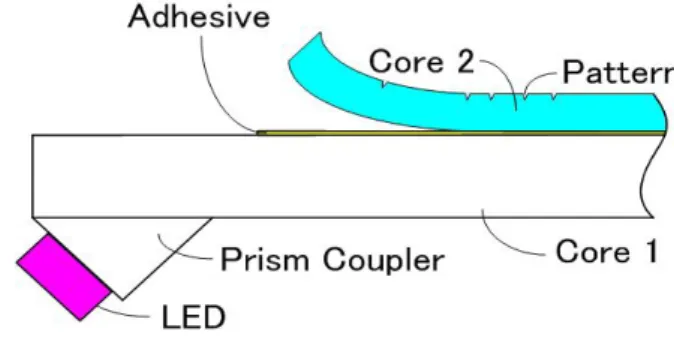
The display unit is composed of transparent double layers of the base sheet (core 1) of about 500 µm thick, acting as a light waveguide, attached with color LEDs and the exchangeable thin image-sheet (core 2) of about 125 µm thick, as shown in figure 1. We used polycarbonate films for both core 1 and core 2. The light of the LED is coupled into the core 1 through the prism coupler and re-coupled to the core 2. Propagating light in the core 2 is scattered by the patterned grooves into the outside to see as an image display.
Fig. 1. Structure of the display unit.
Simple and flexible display unit with an exchangeable
image-sheet using
a thin film light waveguide
Chihiro Sato, Mitsuteru Kimura
Dept. of Electrical Engineering, Tohoku Gakuin University, Tagajo, Miyagi, Japan
TEL:+81-22-368-7162, e-mail: [email protected]
17-4 / C. Sato
• IMID 2009 DIGEST
The prism is designed so as to be that most of light emitted from the LED can be coupled into the core 2 due to the total reflection at the interface between the core (both core 1 and 2) and the air, and the angle θp
of the prism as shown in figure 2 is determined as shown in figure 2. The prism angle θp should be larger
than 43.3º by the Snell’s law taking account of the refractive indices of the prism itself (acrylic resin ) of 1.49, and both core 1 and core 2 (polycarbonate) of 1.59.
We have adopted the angle θp of 45º of the prism in
our experiments.
Fig. 2. Schematic diagram of the waveguide and the propagating light ray.
A part of the propagating light in the thin film core 2 attached on the base sheet of core 1 will be scattered at the grooves as an image pattern formed by the combination of the PC and the cutting plotter as shown in figure 2. In figure 3 grooves formed on the surface of the core 2 (polycarbonate) of 500 µm thick. The image pattern such as a letter and a picture is composed of these grooves.
Fig. 3. Grooves formed on the core 1.
The full color display is performed by overlapping
each color unit composed of the core 1 with LED array of one of three primary colors of RGB and the core 2 attached on it as shown in figure 4. In our display unit an image pixelfor the full color display is only one point because of the overlap structure of each RGB unit, this fact will lead to a fine image display.
Fig. 4. Structure of the full color display unit. 3. Results and discussion
We have ascertained that the letter image by a unit structure shown in figure 1 for each color LED array of RGB can be seen as a scattered light image as shown in figure 5 (a) (blue color image using the blue color LED array) and figure 5 (b) (the image when the display sheet is bent.).
(a)
(b)
Fig. 5. Letter image display by our proposed display unit (a), and its bent image display (b).
17-4 / C. Sato
IMID 2009 DIGEST •
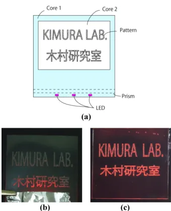
In figure 6 results of the comparison of images from our early stage display unit (b) and the improved one (c) are shown for the image pattern as shown in (a). In our early stage we used the PET film as the base core 1 and grooves as an image pattern are directly formed on this base core 1, however, in the improved oneshown in (c) the polycarbonate films as both the base core 1 and the core 2 attached on it are adopted, namely, we have adopted a double layer core structure, which enable the exchange of the image, with very transparent film of the polycarbonate film for the waveguide material..
(a)
(b) (c)
Fig. 6. Schematic diagram of the image pattern (a) and comparison of images from our early stage display unit (b) and the improved one (c).
In figure 7 the image display of a star with relatively larger area than the letter pattern, which is illuminated by simultaneous turn-on lights from R, G and B LEDs attached at the same prism glued at the end of the base core sheet (core 1). Light intensity of R, G and B LEDs is controlled so as to be white color image, however, near the center of the image pattern are relatively dark. This problem may be overcome by the control of the groove depth or its density.
We have also ascertained the full color image using the overlapping the image sheet units with the same
image pattern of one of the three principal colors of RGB illuminated by each color LED array. In figure 8 each color display of R, G and B in (a) and the display resulting from the overlapping of each color sheet display unit in (b) are shown. Light intensity of R, G and B LEDs is also controlled so as to be white color in the main pattern image.
Fig. 7. Image display of a star illuminated by simultaneous turn-on of R, G, B LEDs attached on the same base core sheet (core 1)
Red Green Blue
(a)
(b)
Fig. 8. Each color display of R, G and B in (a) and the display resulting from the overlapping of each color sheet display unit in (b).
17-4 / C. Sato
• IMID 2009 DIGEST
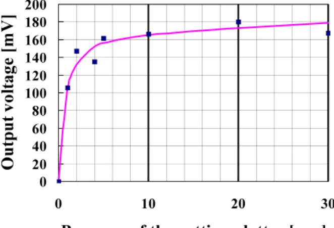
In figure 9 the pressure of the edge of the cutting plotter dependence of the scattered light intensity into the outside (output voltage detected by a reverse biased photodiode) from the test pattern grooves as an image pattern is shown. In this experiment the acrylic resin plate of 3mm thick as the core 1 and a polycarbonate film of 500µm thick (only in this case for test) as the core 2 attached on the core 1 by silicone oil are used for easy test. This will result in that the intensity of the scattering light as an image can be minutely controlled by the edge pressure of the cutting plotter. 0 20 40 60 80 100 120 140 160 180 200 0 10 20 30
Pressure of the cutting plotter [a.u.]
Ou
tpu
t v
olt
ag
e [
mV
]
Fig. 9. Pressure of the edge of the cutting plotter dependence of the scattered light intensity into the outside.
4. Summary
We have proposed a flexible still picture type waveguide display unit, which is able to easily exchange the image pattern with different one and demonstrated its fundamental results including the full color display using the proto-type display unit. We have also demonstrated the image display under its bent state.
This display unit will be promised to be used for applications such as a poster, a sign and an indicator attached on the curved object or the show-window glass board.
5. References
1. Y. Chen, et al., Nature, 423(6936), 136(2003). 2. Y. Funayama, T. Itoh, and M. Kimura, The International Conference on Electrical Engineering