A Study on Stable Motion Control of Humanoid Robot with 24 Joints Based on Voice Command
Woo-Song Lee1*, Min-Seong Kim2, Ho-Young Bae3, Yang-Keun Jung4, Young-Hwa Jung5, Gi-Soo Shin6, In-Man Park7, Sung-Hyun Han8
<Abstract>
We propose a new approach to control a biped robot motion based on iterative learning of voice command for the implementation of smart factory. The real-time processing of speech signal is very important for high-speed and precise automatic voice recognition technology. Recently, voice recognition is being used for intelligent robot control, artificial life, wireless communication and IoT application . In order to extract valuable information from the speech signal, make decisions on the process, and obtain results, the data needs to be manipulated and analyzed. Basic method used for extracting the features of the voice signal is to find the Mel frequency cepstral coefficients. Mel-frequency cepstral coefficients are the coefficients that collectively represent the short-term power spectrum of a sound, based on a linear cosine transform of a log power spectrum on a nonlinear mel scale of frequency. The reliability of voice command to control of the biped robot’s motion is illustrated by computer simulation and experiment for biped walking robot with 24 joint.
Keywords : Biped robot, Voice command, Smart factory, Real-time implementation
1* CEO, SUNJIN TECHNOLOGY Co., Ltd.
2 M.S Course, Dept. of advanced engineering, Kyungnam University.
3 M.S. Course, Manigerment & Industy Graduate School Kyungnam University.
4 CEO, Shinra Information Technology Co., Ltd.
5 CEO, Daehotek Co., Ltd.
6 CEO, ANYTOY Co., Ltd.
7 CEO, lntem Co., Ltd.
8 Dept. of Mechanical Engineering, Kyungnam University.
1. INTRODUCTION
Humanoid robots for entertainment are designed to imitate human or animal movements. Their motions are usually choreographed by hand to move in synchrony with prerecorded speech or music. Animating such robots is a time consuming process.[1]
Voice recognition allows you to provide input to an application with your voice. Just like clicking With mouse, typing on the keyboard, or pressing a key on the phone keypad provides input to an application, voice recognition system provide input by talking. In the desktop world, you need a microphone to be able to do this.[2]
The voice recognition process is performed by a software component known as the speech recognition engine. The primary function of the voice recognition engine is to process spoken input and translate it into text that an application understands. When the user says something, this is known as an utterance.[3]
This system act as means of security measures to reduce cases of fraud and theft due to its use of physical characteristics and traits for the identification of individuals. The earliest methods of biometric identification included fingerprint and handwriting while more recent ones include iris/eye scan, face scan, voice print, and hand print. Voice recognition and identification technology focuses on training the system to recognize an individual’s unique voice characteristics.[4]
Recently, there are a lot of research efforts in the area of intelligent robotics towards the intelligent robots with environmental perception, reasoning, and learning. Among the intelligent robots, biped walking robot have many advantages to the human being’s life. Specially, factors to complicate joint control of a biped walking robot are the problem that a load and friction to be loaded on a joint are turned very greatly according to a walking period. It will be very hard that the gains which stabilize an entire gait control is obtained because every each step of a walking pattern is very various in a degree of error coming true if general and linear controller is applied to the gait control of a biped walking robot.[5]
We apply to control of the biped robot motion a repetitive learning control algorithm based on voice command to biped walking robot.
2. PRINCIPLE OF VOICE RECOGNITION
Basic principles of Voice Recognition are as follows:
2.1 Feature extraction
The extraction of the best parametric representation of acoustic signals is an important task to produce a better recognition performance. The efficiency of this phase is
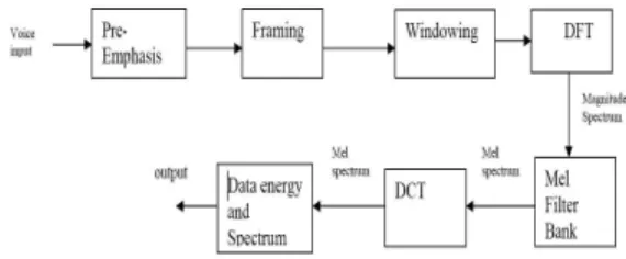
important for the next phase since it affects its behavior. MFCC is based on human hearing perceptions which cannot perceive frequencies over 1KHz. In other words, MFCC is based on known variation of the human ear’s critical bandwidth with frequency.[6-7] A subjective pitch is present on Mel Frequency Scale to capture important characteristic of phonetic in speech. The overall process of the MFCC is shown in Fig 1.
2.1.1 Pre-emphasis
Pre-emphasis refers to a system process designed to increase, within a band of frequencies, the magnitude of some (usually higher) frequencies with respect to the magnitude of the others(usually lower) frequencies in order to improve the overall SNR. Hence, this step processes the passing of signal through a filter which emphasizes higher frequencies. This process will increase the energy of signal at higher frequency.[8-9]
2.1.2 Framing
The process of segmenting the speech samples obtained from an ADC into a small frame with the length within the range of 20 to 40 msec. The voice signal is divided into frames of N samples.[10-11] Adjacent frames are being separated by M (M<N).
2.1.3 Hamming windowing
Hamming window is used as window shape by considering the next block in feature extraction processing chain and
integrates all the closest frequency lines. The Hamming window is represented as shown in equation (1)
If the window is defined as , 0 ≤
≤ where
= number of samples in each frame
= Output signal
= input signal
= Hamming window, then the result of windowing signal is shown below:
(1)
2.1.4 Fast fourier transform
To convert each frame of samples from time domain into frequency domain is being used. The Fourier Transform is used to convert the convolution of the glottal pulse
and the vocal tract impulse response
. in the time domain.[12-13]
This statement supports as shown in equation (2)
(2)
If , and are the Fourier Transform of , and
respectively.
Fig. 1 MFCC Block Diagram
2.1.5 Mel filter bank processing
The frequencies range in spectrum is very wide and voice signal does not follow the linear scale. Each filter’s magnitude frequency response is triangular in shape and equal to unity at the Centre frequency and decrease linearly to zero at centre frequency of two adjacent filters.
Then, each filter output is the sum of its filtered spectral components. After that the following equation as shown in equation (3) is used to compute the Mel for given frequency f in :
log (3)
2.1.6 Discrete cosine transform
This is the process to convert the log Mel spectrum into time domain using DCT. The result of the conversion is called Mel Frequency Cepstrum Coefficient. The set of coefficient is called acoustic vectors.
Therefore, each input utterance is transformed into a sequence of acoustic vector.[14]
2.1.7 Delta energy and delta spectrum The voice signal and the frames changes, such as the slope of a formant at its transitions. Therefore, there is a need to add features related to the change in cepstral features over time. 13 delta or velocity features (12 cepstral features plus energy), and 39 features a double delta or acceleration feature are added. The energy in
a frame for a signal x in a window from time sample t1 to time sample t2, is represented as shown below in equation (4)
(4)
Where = signal
Each of the 13 delta features represents the change between frames corresponding to cepstral or energy feature, while each of the 39 double delta features represents the change between frames in the corresponding delta features.[15]
3. MOTION CONTROL
Consider the biped robot with 12 D.O.F whose dynamics is
(5)
where ∈ denotes the joint angles,
∈× is the inertia matrix,
∈ ∈× is the centripetal plus coriolis force vector,
∈ is the gravitational plus frictional forces, ∈ is the joint control input vector, and d is the unknown disturbance vector which is assumed to be bounded. Here, the time argument t has been omitted for notational brevity. The disturbance vector d includes the constraint force in the double-support phase and the moments caused
by the motions in other planes as well as the pure external disturbances.[16-17]
Since the biped robot is performing a repetitive task of walking, the desired robot trajectories and the unknown inverse dynamics inputs can be specified using T-periodic functions as follows:
(6)
where the subscript d represents desired trajectories and the desired input is given by
(7)
Then, the fundamental learning control problem is to find a learning controller with which the robot trajectory tracks for all
∈
To simplify the learning control problem, the constraint force is neglected at the moment by assuming a soft touchdown of swing leg at the end of single support phase.
Then, the learning controller is constructed as
(8)
where is the local feedback control input at each joint and is the feedforward learning input.[18-19]
The feedback control input is in charge of stabilizing the closed-loop system and is computed from the conventional proportional
integral-derivative(PI) control scheme.
(9)
where . The learning control input compensates for the nonlinearity of uncertain biped robot and its learning rule is defined as
(10)
where z = e + a e (a >0), fi is the positive learning gain and is the initial condition of learning input.[20-21]
The projection operation is to limit its argument within a bounded convex set and defined as
if
if
≤ ≤
if
(11)
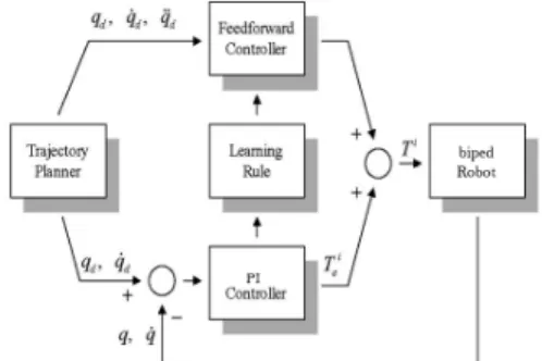
Fig. 2 represents the schematic diagram of the robot system controller.
Fig. 2 The schematic diagram of the robot system controller
4. SIMULATION AND EXPERIMENTAL RESULTS
4.1 Simulation results
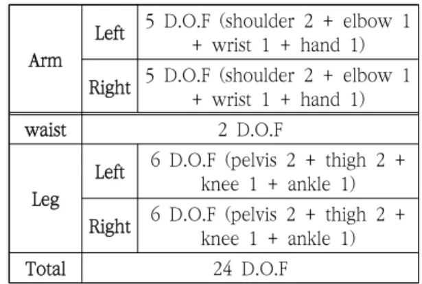
The learning control schemes are applied to control of a real biped walking robot with 24 D.O.F. Fig 3 represents the Biped robot model with 24 joint. Table. 1 shows the degree of freedom for biped robot. Fig. 4 represents locomotion phase of biped robot.
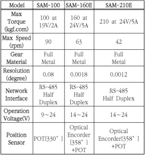
Table. 2 shows the specification of biped robot. Table. 3 shows the specification of robot actuators. Fig. 5 represents walking pattern of biped robot. Fig. 6 represents the total structure of robot control system.
Fig. 3 Biped robot model with 24 joint
Fig. 4 Locomotion phase of biped robot
Arm
Left 5 D.O.F (shoulder 2 + elbow 1 + wrist 1 + hand 1) Right 5 D.O.F (shoulder 2 + elbow 1
+ wrist 1 + hand 1)
waist 2 D.O.F
Leg
Left 6 D.O.F (pelvis 2 + thigh 2 + knee 1 + ankle 1) Right 6 D.O.F (pelvis 2 + thigh 2 +
knee 1 + ankle 1)
Total 24 D.O.F
Table. 1. Degree of freedom of biped robot
Height 95.6[cm]
Weight 9.0[kg]
Actuator
Head SAM-100
Arm
DC Servo Motor + Harmonic speed reducer
+ Ball screw
Waist
DC Servo Motor + Harmonic speed reducer
+ Ball screw + Gravity compensator
Leg
DC Servo Motor + Harmonic speed reducer
+ Ball screw
Control unit
Main controller
Embedded Motion Controller STM32F103 x 1 Joint
controller
SAM I/F Controller STM32F103 x 1 Power
capacity 18.0Vdc∼24.0Vdc
Sensory device
Gyrometer, Accelaration, Geomagnetic Operation
device Notebook PC with wireless LAN Table. 2. Specification of robot
Fig. 5 Walking pattern of biped robot
Model SAM-100 SAM-160E SAM-210E
Max Torque (kgf.com)
100 at 19V/2A
160 at
24V/5A 210 at 24V/5A Max Speed
(rpm) 90 63 42
Gear Material
Full Metal
Full Metal
Full Metal Resolution
(degree) 0.08 0.0018 0.0012
Network Interface
RS-485 Half Duplex
RS-485 Half Duplex
RS-485 Half Duplex Operation
Voltage(V) 9∼24 14∼24 14∼24
Position
Sensor POT[330°]
Optical Encorder
[358°]
+POT
Optical Encorder[358°]
+POT Table. 3 The specification of robot actuators
Fig. 6 The total structure of robot control system
Fig. 7 5th joint trajectory with PI feedback control learning control input
Fig. 8 6th joint trajectory with PI feedback control and without learning control input
Fig. 9 5th joint trajectory with PI plus learning controller after 20th trial
Fig. 10 6th joint trajectory with PI plus learning controller after 20th trial
Fig. 7 represents the 5th joint trajectory with PI feedback control learning control input. Fig. 8 represents the 6th joint trajectory with PI feedback control and without learning control input. Fig. 9 represents the 5th joint trajectory with PI plus learning controller after 20th trial. Fig. 10 represents the 6th joint trajectory with PI plus learning controller after 20th trial. Fig. 11 represents the plots of rms errors versus iteration number. Throughout the simulation, the proposed learning controller shows a good performance of tracking even
when they do not use the exact dynamic model of the biped walking robot.
4.2 Experiments results
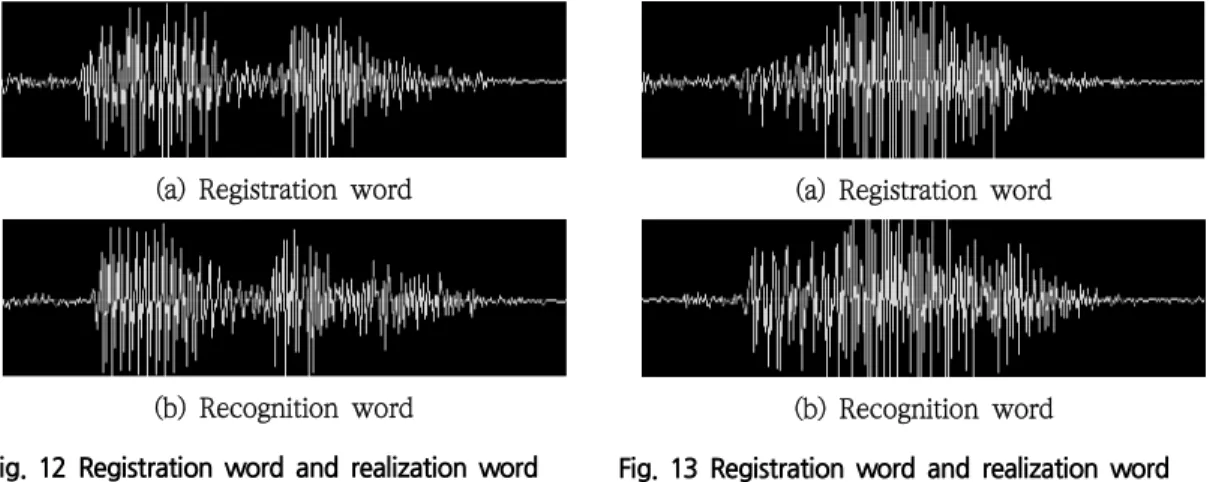
Fig. 11 represents the voice recognition model. Fig. 12 represents the registration word and realization word about "Junbi". Fig.
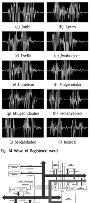
13 represents the registration word and realization word about “Apuro”. Fig. 14 represents the wave of registered word. Fig.
15 represents the configuration of the voice preprocessing unit. Fig. 16 represents the
Fig. 11 Voice recognition model
(a) Registration word
(b) Recognition word
Fig. 12 Registration word and realization word about “Junbi”
(a) Registration word
(b) Recognition word
Fig. 13 Registration word and realization word about “Apuro”
signal flow of the controller module. Fig. 17 represents the Performance experiment scene of voice recognition.
(a) Junbi (b) Apuro
(c) Dwilo (d) Jwahoejeon
(e) Uhoejeon (f) Mulgeonjaba
(g) Mulgeondeuleo (h) Seolabyeoleo
(i) Seolabdadeo (j) Jeondal Fig. 14 Wave of Registered word
Fig. 15 Configuration of the voice preprocessing unit
Fig. 16 The signal flow of the controller module
(a) Junbi (b) Apuro
(c) Jasenajchwo (d) Mulgeonjaba
(e) Mulgeondeuleo (f) wahoejeon
(g) Apuro (h) Jeondal
Fig. 17 Performance experiment scene of voice recognition
Fig. 18 Voice recognition experiment result I
Fig. 19 Voice recognition experiment result Ⅱ
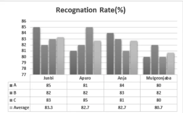
Fig. 18 represents the voice recognition experiment result I. Fig. 19 represents the voice recognition experiment result II.
5. CONCLUSION
This study proposed a new approach to control the motion of biped robot based on voice command for unmanned factory automation. The proposed joints servo controller is composed of local PI feedback control scheme and a feedforward input learning scheme for real-time implementing
the control strategy at each joint. The learning control scheme learns the approximate inverse dynamics input of biped walking robot and uses the learned input pattern to generate an input profile of different walking motion from iterative learning of voice command. The feasibility of the proposed method has been verified through computer simulation and experimental results with dynamics model of 24 D.O.F biped robot based on voice recognition.
References
[1] Cappozzo, A., Leo, T. and Pedot Ti, "A. general computing method for the analysis of human locomotion," J Biomechanics 8, pp.307-320, (1975).
[2] J. A. Albus, "Outlineforatheory ofintelligence,"
IEEE Trans. on Systems, Man and Cybernetics, vol. 21, no.3, pp. 473-509, (1991).
[3] R-A.Brooks,"A robust layered control system for a mobile robot," IEEE Journal ofRobotics &
Automation, vol RA-2, no. 1, pp. 14-23, (1986).
[4] Nubar, Y. and Contitni, R "A minimumprinciple in biomechanics," Bull. OfMath. Biophys., 23, pp.377-391, (1961).
[5] Crowninshield, R D. "Use of optimization techniques to predict muscle forces," J Biomech Eng. 100, pp.88-92, (1978).
[6] Seireg, A. and Arvikar, R. J. "The prediction of muscular load sharing andjoint forces in the lower extremity during walking," J Biomechanics 8, pp.89-102, (1975).
[7] G Capi, S. Kaneko, K. Mitobe, L. Barolli, and Y. Nasu, "Optimal trajectory generation for a prismatic joint biped robot using genetic
algorithms," Jour Robotics and Autonomous Systems, vol. 38, no. 2, pp. 119-128, (2002).
[8] M. Gen and R Cheng, "Genetic algorithms and engineering optimization," Wiley, (2000).
[9] Yamaguchi, G T. and Zajac, E E. "Restoring unassisted natural gait to paraplegics via functional neuromuscular stimulation," A Computer Simulation Study, IEEE Trans. Biomed Eng. 37, pp.886-902. (2001).
[10] G G Jin, "Genetic algorithms and their applications," Kyo Woo Sa, (2002).
[11] M. Srinivas and L. M. Patnaik, "Genetic algorithms: A Survey," Computer, vol. 27, no.
6, pp. 17-24, (1994).
[12] G Kinoshita, T. Kimura and M. Shimojo,
"Dynamic sensing experiments of reaction force distributions on the sole of a walking humanoid robot’, IEEE Intl, Conference on intelligent robot and Systems, pp. 1413-1418, (2003).
[13] B. J, Jung, J. S. Kong, B. H. Lee, J. G Kim,
"Backlash compensation for a humanoid robot using disturbance observer’, IECON04. (2004).
[14] Huu-Cong Nguyen, Woo-Song Lee, “A study on The Real-Time Implementation of Intelligent Control Algorithm for Biped Robot Stable Locomotion” The Korea Society of Industrial Application Vol.18, No.4, pp.224-230, (2015).
[15] G. Tevatia and S. Schaal, “Inverse kinematics for humanoid robots, “Proc. of IEEE Int. Conf.
on Robotics and Automation, pp.294-299, 2000.
[16] C. L. Shih, et al., "Trajectory Synthesis and physical admissibility for a biped robot during the single-support phase," Proc. of IEEE Int.
Conf. on Robotics and Automation, pp.1646-1652, (1990).
[17] H. Takeuchi, “Development of MEL HORSE,”
Proc. of IEEE Int. Conf. on Robotics and Automation, pp. 3165-3171, 2001. [4] M.Yagi,
“Synthesis of control strategies forplanar biped robot locomotion in the presence of disturbances, “Univ. of Winconshin-Madisan Robotics Lab. Tech. Report, no. RL-97002,
(1997).
[18] Y. W. Sung, S-Y Yi, “A miniature humanoid robot that can walk up and down stairs, “Proc.
of the 32nd ISR, pp.1463-1468, (2001).
[19] T. Morita, et al., “Design and control of mobile manipulation system for human symbiotic humanoid : Hadaly-2, “Proc. of IEEE Int. Conf. on Robotics and Automation, pp. 1315-1320, (1998).
[20] J. Furusho and A. Sano, “Sensor-based control of nine-link biped, “Int. Journal of Robotics Research, vol. 9, no 2, pp. 62-82, (1990).
[21] J. Pratt, P. Dilworth and G. Pratt, “Virtual model control of a bipedal walking robot,
“Proc. of IEEE Int. Conf. on Robotics and Automation, pp. 193-198, (1997).
(Manuscript received November 28, 2017; revised December 22, 2017; accepted January 8, 2018.)