Numerical Simulation
NGUYEN BA HUNG, OCKTAECK LIM
†School of Mechanical Engineering, University of Ulsan, Mugeo-dong, Nam-gu, Ulsan 44610 Korea
Abstract >> The purpose of this study is to investigate the effects of changing dimension of a soft tube in a peristaltic pump on deformation, stress and fluid flow rate of the peristaltic pump. Geometries of the peristaltic pump is created in a Catia drawing software based on specifications of a real peristaltic pump. Afterwards, the geometries of this pump is imported into a commercial Ansys software to calculate deformation, stress, and fluid flow rate of this pump. The simulation results showed that the deformation and stress of the soft tube is increased by increasing soft tube diameter from 2 mm to 4 mm. When the tube diameter is increased to 5 mm and tube thickness is reduced to 0.5 mm, the soft tube is damaged. The highest fluid flow rate could be found at the tube thickness and diameter of 1 mm and 4 mm, respectively.
Key words : Peristaltic pump(연동식 펌프), Deformation(변형), Stress(스트레스), Fluid flow rate(유량율)
†Corresponding author : [email protected]
Received : 2015.9.17 in revised form: 2015.11.6 Accepted : 2015.12.30 Copyright ⓒ 2015 KHNES
Nomenclature
: fluid density, kg/m
3ufluid : velocity of fluid, m/s
: viscosity , Pa.s p : pressure Pa
: stress tensor n : normal vector
Subscripts
fluid : fluid solid : solid
1. Introduction
A peristaltic pump is a type of positive displacement
pump used for pumping a variety of fluids
1-5). The fluid
is contained within a flexible tube fitted inside a circular
pump casing. A rotor with a number of rollers, shoes,
wipers or lobes attached to the external circumference of
the rotor compresses the flexible tube. Fig. 1 describes
components of a peristaltic pump.
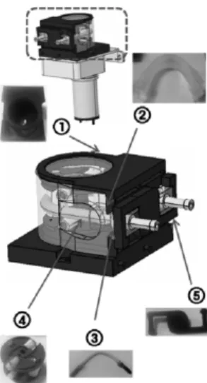
Fig. 1 Model of peristaltic pump
1-pump cover, 2-cover bracket, 3-tube, 4-pump housing, 5-Roller bracket
Fig. 2 The main components of the research peristaltic pump
Fig. 3 Dimensions of soft tube. (a) d = 5 mm, (b) d = 4 mm, (c) d = 3 mm, (d) d = 2 mm
For operating principle, as the rotor turns, the part of the tube under compression is pinched closed thus forcing the fluid to be pumped to move through the tube.
Additionally, as the tube opens to its natural state after the passing of the cam fluid flow is induced to the pump.
This process is called peristalsis and is used in many biological systems such as the gastrointestinal tract.
Typically, there will be two or more rollers, or wipers, occluding the tube, trapping between them a body of fluid. The body of fluid is then transported, at ambient pressure, toward the pump outlet. Peristaltic pumps may run continuously, or they may be indexed through partial revolutions to deliver smaller amounts of fluid. Peristaltic pumps are applied for injection of water treatment agents such as chlorine, soda ash, and hydrogen peroxide. Besides, the peristaltic pumps are also used in industrial equipments including car wash equipment, food processing equipment, printing equipment.
In the peristaltic pump, the only part of the pump in contact with the fluid being pumped is the interior of the tube, it is easy to sterilize and clean the inside surfaces of the pump. Besides, the peristaltic pumps are able to handle slurries, viscous, shear-sensitive and aggressive fluids. In addition, pump design prevents backflow and siphoning without valves.
One of important parts of peristaltic pump is soft tube.
It is important to select tubing with appropriate chemical resistance towards the liquid being pumped. Type of tubing commonly used in peristaltic pumps include polyvinyl chloride, silicone rubber, fluoropolymer, pharmed.
The flexible tubing will tend to degrade with time and require periodic replacement. Therefore, a numerical investigation about the deformation and stress of the soft tube should be conducted to predict the behavior of the tube.
In this paper, a simulated peristaltic pump is established based on specifications of a real peristaltic pump, shown in Fig. 2.
In this pump, the main components including roller
and soft tube are selected to simulate. The objective of
the investigation is to simulate and optimize a peristaltic
Fig. 5 Geometries of tube, roller and fluid
Table 1 Parameters are used in simulation
Geometries Material
Tube Silicon
Roller Stainless steel
Water Water
Boundary face 1 Structural steel Boundary face 1 Structural steel
(roller and tube), therefore the mathematical models include fluid model and solid model.
Fig. 4 Mathematical models of the fluid-structure interaction
where is the fluid density (kg/m
3), ufluid is the velocity (m/s), is the viscosity (P.s), p is the pressure (Pa), is stress tensor, n is normal vector.
In this paper, the Navier-Stokes equations are used first to calculate fluid flow and fluid stresses. Afterwards, the calculated fluid stresses is applied on solid boundaries to solve the deformation in solids. The combination of the mathematical models for the fluid-structure interaction is shown in Fig. 4.
3.2 Simulation setup
After making the geometries of peristaltic pump in Catia software, the geometries are imported into Ansys Workbench software. In the interface of Ansys Workbench, the geometries are shown as Fig. 6.
The next step is to generate mesh the geometries with
the appropriate mesh sizes. In general, the mesh size is
chosen at 1 mm. If the mesh size is increased over this
value, the simulation time is reduced, but the simulation
Fig. 6 Geometries of peristaltic pump in Ansys Workbench
Fig. 7 Meshing generation
Fig. 8 Fixed boundary conditions
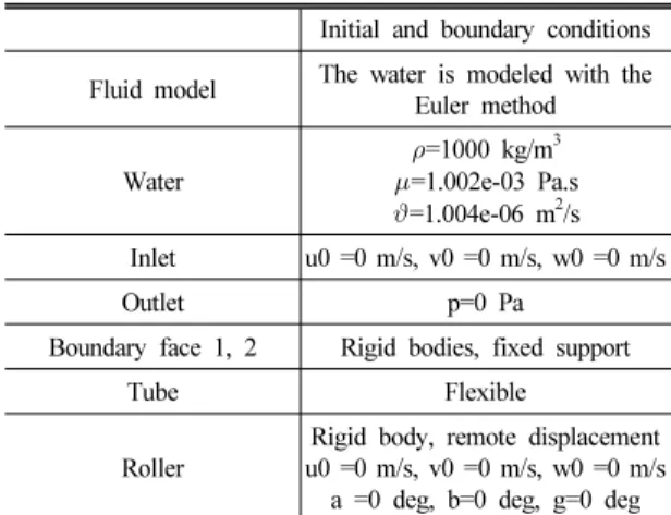
Table 2 Initial and boundary conditions
Initial and boundary conditions
Fluid model The water is modeled with the Euler method
Water
=1000 kg/m
3=1.002e-03 Pa.s
=1.004e-06 m
2/s Inlet u0 =0 m/s, v0 =0 m/s, w0 =0 m/s
Outlet p=0 Pa
Boundary face 1, 2 Rigid bodies, fixed support Tube Flexible
Roller
Rigid body, remote displacement u0 =0 m/s, v0 =0 m/s, w0 =0 m/s
a =0 deg, b=0 deg, g=0 deg
results seems to be not correct. However, if the mesh size is reduced lower 1 mm, the simulation results can become more correctly, but the simulation time is increased due to so small mesh size. In this simulation, the soft tube is selected as an important part because it relates directly to deformation as well as stress. Therefore, the mesh size of soft tube is chosen at 0.5 mm, while the mesh size of the other parts are chosen at 1 mm. By generating mesh as mentioned, the tube contains 14697 cells, with 21424 nodes. The picture of peristaltic pump after generating mesh is shown in Fig. 7.
The boundary conditions include the fixed support from boundary face 1, 2, which are displayed by violet as shown in Fig. 8. The initial and other boundary conditions are shown in Table 2.
The next step is to apply motion for the roller. The fist state of roller is static and only contact with the tube, (displacement in X axis direction x = 0 mm). By applying motion for the roller, it will move with x = 4 mm, and then it will rotate around Y axis with step of Δϕ = 2.5 degree at each time step. In Ansys Workbench, the Remote Displacement is used as a tool to control the motion of roller.
4. Simulation results
4.1 Deformation
Fig. 9 shows that the tube is damaged when the thickness
and diameter of the tube is t = 0.5 mm and d = 5 mm,
Fig. 9 Deformation of tube at t = 0.5 mm, d = 5 mm
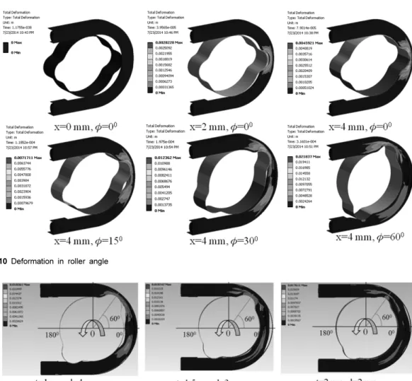
Fig. 10 Deformation in roller angle
Fig. 11 Deformation versus thickness and diameter of the tube
respectively. Therefore, this dimension is eliminated during the simulation. The deformation of the tube with larger thickness are shown in Fig. 10. Therein, the roller
are also described in Fig. 11. It can be seen that, the
maximum deformation is found at thickness and diameter
of tube are t = 1 mm, d = 4 mm, respectively. This can be
also observed in Fig. 12, which describes the deformation
and position of roller in time.
Fig. 12 Deformation and position of roller versus time
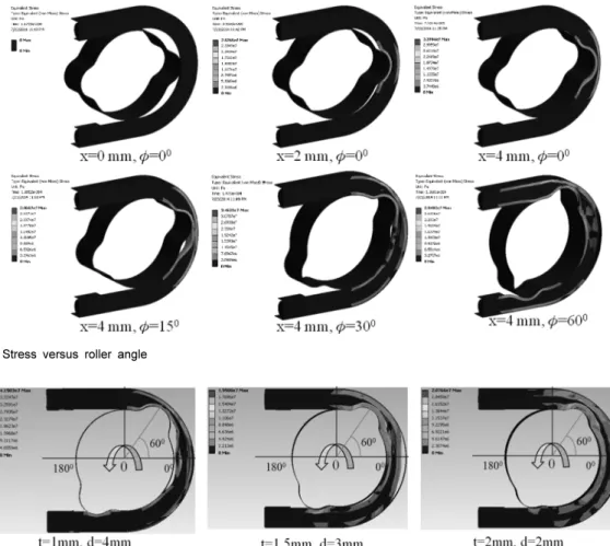
Fig. 13 Stress versus roller angle
Fig. 14 Stress versus thickness and diameter of the tube
4.2 Stress
Fig. 13 shows the stress of the tube and fluid, in which, the maximum stress is found at coordinate x = 4 mm, = 30 degree. As a result of maximum deformation detected at t = 1 mm and d = 4 mm, the maximum stress is also found correspondingly, as shown in Fig. 14 and Fig. 15.
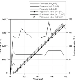
4.3 Fluid flow rate